Page is loading ...

World Class Design | World Class Function | 30 Years Expertise In Industrial Motor Control
HG103521 ISSL
PRODUCT MANUAL:
JL/X DIGITAL AC
SLIP RING DRIVE

2
Table of Contents
1 Warnings .................................................................................................. 4
1.1 General warnings .......................................................................................................... 4
1.2 Warnings and instructions ............................................................................................... 4
1.3 General risks ................................................................................................................ 6
1.4 Summary of further warnings........................................................................................... 7
2 Introduction .............................................................................................. 8
2.1 Operation of Slip Ring Motor ............................................................................................ 9
2.1.1 Stator Voltage Control ................................................................................................. 9
2.1.2 Bi-directional control using the JLX ................................................................................. 9
2.1.3 Rotor Control to optimise torque across speed range .......................................................... 10
2.1.4 Hyper-synchronous regeneration ................................................................................... 11
2.2 Notes on configuration and the use of this manual .............................................................. 12
2.3 Notes on the use of the JL/X MMI .................................................................................... 12
3 Control terminals ...................................................................................... 12
3.1 Control terminals electrical specifications ........................................................................ 12
3.1.1 Universal Inputs (UIP2 – UIP9, terminals 2 to 9) ................................................................. 12
3.1.2 Analogue Outputs (AOP1 – AOP3, terminals 10 to 12) ........................................................... 12
3.1.3 Digital Inputs (DIP1 – DIP4, terminals 14 to 17) ................................................................. 12
3.1.4 Digital Input/Outputs (DIO1 – DIO4, terminals 18 to 21) ....................................................... 13
3.1.5 Digital Outputs (DOP1 – DOP3, terminals 22 to 24) ............................................................. 13
3.2 Control terminals default functions ................................................................................. 14
3.2.1 Universal Inputs UIP2 – UIP9 (terminals 2 to 9) .................................................................. 14
3.2.2 Analogue Outputs AOP1 – AOP3 (terminals 10 to 12) and Iarm (terminal 29)............................... 14
3.2.3 Digital Inputs DIP1 – DIP4 (terminals 14 to 17) .................................................................. 14
3.2.4 Digital Input/Outputs DIO1 – DIO4 (terminals 18 to 21) ........................................................ 15
3.2.5 Digital Outputs DOP1 – DOP3 (terminals 22 to 24) .............................................................. 15
3.3 Non-programmable terminals (terminals 25 to 53) .............................................................. 15
3.3.1 Control board terminals .............................................................................................. 15
3.3.2 Power board terminals ............................................................................................... 16
4 Rating Tables .......................................................................................... 17
4.1 Rating Table for JL/X standard duty versions ..................................................................... 17
4.2 Rating Table for JL/XHD high duty versions ....................................................................... 18
4.3 Environment ratings .................................................................................................... 19
5 Basic wiring diagrams ................................................................................. 20
5.1 Basic power control diagram .......................................................................................... 20
5.2 Basic analogue bipolar input speed control (as shipped, default configuration) ......................... 21
5.3 Basic analogue unipolar input speed control (as shipped, default configuration) ........................ 22
5.4 Basic joystick/digital input speed control (3-key reset configuration). ..................................... 23
5.5 Basic analogue unipolar input current control (as shipped, default configuration) ...................... 24
5.6 Basic joystick/digital input current control (3-key reset configuration). ................................... 25
5.7 Rotor resistance control ............................................................................................... 26
5.8 Brake control ............................................................................................................. 27
5.9 Notes for users of the JLXD stack driver ........................................................................... 28
5.9.1 Existing or replacement stator current feedback ACCTs ....................................................... 28
5.9.2 Stator voltage feedback .............................................................................................. 28
5.9.3 JLXD/pulse transformer location ................................................................................... 28
5.9.4 EL1,2,3 supplies ....................................................................................................... 28
5.10 Setting up communications with Savvy software ................................................................ 29
5.10.1 JL/X not fitted with drive.web board ............................................................................ 29
5.10.2 JL/X fitted with drive.web board ................................................................................. 30
5.11 Basic calibration ........................................................................................................ 33
5.11.1 Special technique for high voltage tachogenerators .......................................................... 34
5.11.2 Special technique for reducing JL/X current rating ........................................................... 34
5.12 Functional settings ..................................................................................................... 36
5.12.1 Ramp times ........................................................................................................... 36
5.12.2 Brake settings ......................................................................................................... 37
5.12.3 Hyper-synchronous detection settings ........................................................................... 40
5.12.4 Scaling the external speed demand and setting the hyper-synchronous demand detector ............ 42

3
5.12.5 Adjusting stator firing angle minimum delay ................................................................... 45
5.12.6 Rotor resistance control settings .................................................................................. 47
5.13 Speed and current loop tuning ....................................................................................... 49
5.13.1 Current loop tuning .................................................................................................. 49
5.13.2 Speed loop tuning .................................................................................................... 57
5.13.3 Special techniques for highly inductive stators ................................................................ 64
6 Alarms ................................................................................................... 65
6.1 Stator Overcurrent ....................................................................................................... 66
6.2 Overspeed .................................................................................................................. 66
6.3 Stator Overvoltage ....................................................................................................... 66
6.4 Missing pulse ............................................................................................................... 66
6.5 Stall .......................................................................................................................... 67
6.6 Motor Thermistor (T30) ................................................................................................. 67
6.7 Heatsink Overtemp ...................................................................................................... 67
6.8 Shorted Digital Output .................................................................................................. 67
6.9 Bad Reference Exchange ............................................................................................... 68
6.10 Contactor Lockout ....................................................................................................... 68
6.11 User or drive.web ....................................................................................................... 68
6.12 Synchronization loss .................................................................................................... 68
6.13 EL1/2/3 Phase Loss ...................................................................................................... 68
6.14 Special note concerning speed feedback mismatch alarm ..................................................... 69
7 Mechanical Dimensions ............................................................................... 70
7.1 Frame 2 JL/X130 – 270 and JL/XHD75 - 160 ....................................................................... 70
7.2 Frame 4 JL/X370 – 780 and JL/XHD220- 470 ...................................................................... 71
7.3 Frame 5 JL/X860 – 1680 and JL/XHD520 - 1010 .................................................................. 72
8 Venting .................................................................................................. 73
8.1 General venting information for frame 4 and 5 ................................................................... 73
8.2 When venting kit impractical for frame 4 and 5 .................................................................. 73
8.3 Venting kit for frame 4 .................................................................................................. 73
8.4 Frame 4 and 5 venting kit diagram ................................................................................... 74
8.5 Venting kit for frame 5 .................................................................................................. 74
8.6 Air supply to enclosure ................................................................................................. 75
8.7 Exhaust air ................................................................................................................. 75
8.8 Venting summary ......................................................................................................... 75
8.9 Diagram of airflow for frame 4 and 5 ................................................................................ 76
9 Product rating labels .................................................................................. 77
10 Semiconductor fusing ............................................................................... 78
10.1 L1,2,3 supply fusing total clearing I
2
t ratings ..................................................................... 78
10.1.1 Standard 150% overload models ................................................................................... 78
11.1.2 HD 250% overload models .......................................................................................... 78
10.2 Sprint Electric part numbers for L1,2,3 supply fuses/fuseholders ........................................... 79
10.2.1 Standard 150% overload models ................................................................................... 79
10.2.2 HD 250% overload models .......................................................................................... 79
11 Line reactors ......................................................................................... 80
12 Installation ........................................................................................... 80
12.1 Lifting the frame 4 and 5 units ....................................................................................... 80
12.2 Terminal tightening torques .......................................................................................... 80
12.3 Forces applied to the power terminals ............................................................................. 81
12.4 Installation guide for EMC .............................................................................................. 81
12.5 Guidelines for earthing and screening .............................................................................. 81
12.6 Guidelines when using supply filters ................................................................................ 82
13 JL/X block diagrams ................................................................................ 83
13.1 Normal page default block diagrams ................................................................................ 83
13.2 3-key reset page default block diagrams ........................................................................... 90
14 Record of manual modifications .................................................................. 91

4
1 Warnings
1.1 General warnings
PLEASE READ AND UNDERSTAND THIS MANUAL BEFORE APPLYING POWER TO THE JL/X DRIVE UNIT
The JL/X motor drive controller is an open chassis component for use in a suitable enclosure
Drives and process control systems are a very important part of creating better quality and value in the goods for
our society, but they must be designed, installed and used with great care to ensure everyone's SAFETY.
Remember that the equipment you will be using incorporates...
High voltage electrical equipment
Powerful rotating machinery with large stored energy
Heavy components
Your process may involve...
Hazardous materials
Expensive equipment and facilities
Interactive components
Always use qualified personnel to design, construct and operate your systems and keep SAFETY as your primary
concern.
Thorough personnel training is an important aid to SAFETY and productivity.
SAFETY awareness not only reduces the risk of accidents and injuries in your plant, but also has a direct impact on
improving product quality and costs.
If you have any doubts about the SAFETY of your system or process, consult an expert immediately. Do not
proceed without doing so.
HEALTH AND SAFETY AT WORK
Electrical devices can constitute a safety hazard. It is the responsibility of the user to ensure the compliance of the
installation with any acts or bylaws in force. Only skilled personnel should install and maintain this equipment after
reading and understanding this instruction manual. If in doubt refer to supplier.
Important note: The contents of this manual are believed to be accurate at the time of printing. However the
manufacturers reserve the right to change the content and product specification without notice. No liability is
accepted for omissions or errors. No liability is accepted for the installation or fitness for purpose or application of
the JL/X motor drive unit.
1.2 Warnings and instructions
WARNING
Only qualified personnel who thoroughly understand the operation of this equipment
and any associated machinery should install, start-up or attempt maintenance of this
equipment. Noncompliance with this warning may result in personal injury and/or
equipment damage. Never work on any control equipment without first isolating all
power supplies from the equipment. The JL/X and motor must be connected to an
appropriate safety earth. Failure to do so presents an electrical shock hazard.
DANGER
ELECTRIC SHOCK RISK

5
CAUTION
This equipment was tested before it left the factory. However, before installation
and start-up, inspect all equipment for transit damage, loose parts, packing
materials etc. This product conforms to IP00 protection. Due consideration
should be given to environmental conditions of installation for safe and reliable
operation. Never perform high voltage resistance checks on the wiring without
first disconnecting the product from the circuit being tested.
STATIC SENSITIVE
This equipment contains electrostatic discharge (ESD) sensitive
parts. Observe static control precautions when handling, installing
and servicing this product.
THESE WARNINGS AND INSTRUCTIONS ARE INCLUDED TO ENABLE THE USER TO OBTAIN
MAXIMUM EFFECTIVENESS AND TO ALERT THE USER TO SAFETY ISSUES
APPLICATION AREA: Industrial (non-consumer) "Motor speed control utilising slip ring motors".
PRODUCT MANUAL: This manual is intended to provide a description of how the product works. It is not intended
to describe the apparatus into which the product is installed.
This manual is to be made available to all persons who are required to design an application, install, service or
come into direct contact with the product.
APPLICATIONS ADVICE: Application advice and training is available from Sprint Electric.

6
1.3 General risks
INSTALLATION: THIS PRODUCT IS CLASSIFIED AS A COMPONENT AND MUST BE USED IN A
SUITABLE ENCLOSURE
Ensure that mechanically secure fixings are used as recommended.
Ensure that cooling airflow around the product is as recommended.
Ensure that cables and wire terminations are as recommended and clamped to required
torque.
Ensure that a competent person carries out the installation and commissioning of this
product.
Ensure that the product rating is not exceeded.
APPLICATION RISK: ELECTROMECHANICAL SAFETY IS THE RESPONSIBILITY OF THE USER
The integration of this product into other apparatus or systems is not the responsibility of
the manufacturer or distributor of the product.
The applicability, effectiveness or safety of operation of this equipment, or that of other
apparatus or systems is not the responsibility of the manufacturer or distributor of the
product.
Where appropriate the user should consider some aspects of the following risk assessment.
RISK ASSESSMENT: Under fault conditions or conditions not intended.
1. The motor speed may be incorrect. 2. The motor speed may be excessive.
3. The direction of rotation may be incorrect. 4. The motor may be energised.
In all situations the user should provide sufficient guarding and/or additional redundant monitoring and safety
systems to prevent risk of injury. NOTE: During a power loss event the product will commence a sequenced shut
down procedure and the system designer must provide suitable protection for this case.
MAINTENANCE: Maintenance and repair should only be performed by competent persons using only the
recommended spares (or return to factory for repair). Use of unapproved parts may create a hazard and risk of
injury.
WHEN REPLACING A PRODUCT IT IS ESSENTIAL THAT ALL USER DEFINED
PARAMETERS THAT DEFINE THE PRODUCT'S OPERATION ARE CORRECTLY
INSTALLED BEFORE RETURNING TO USE. FAILURE TO DO SO MAY CREATE A
HAZARD AND RISK OF INJURY.
PACKAGING: The packaging is combustible and if disposed of incorrectly may lead to the generation of
lethal toxic fumes.
WEIGHT: Consideration should be given to the weight of the product when handling.
REPAIRS: Repair reports can only be given if the user makes sufficient and accurate defect reporting.
Remember that the product without the required precautions can represent an electrical hazard and risk of injury,
and that rotating machinery is a mechanical hazard.
PROTECTIVE INSULATION:
1. All exposed metal insulation is protected by basic insulation and user bonding to earth i.e. Class 1.
2. Earth bonding is the responsibility of the installer.
3. All signal terminals are protected by basic insulation, and the user earth bonding. (Class 1). The purpose of this
protection is to allow safe connection to other low voltage equipment and is not designed to allow these terminals to
be connected to any un-isolated potential.
Important note: It is essential that all the following warnings are read and understood.

7
1.4 Summary of further warnings
This summary is provided for convenience only. Please read the entire manual prior to first time product use.
0V on T13 must be used for protective clean earth connection.
Do not rely on any JL/X function to prevent the motor from operating when personnel are undertaking maintenance,
or when machine guards are open. Electronic control is not accepted by safety codes to be the sole means of
inhibition of the controller. Always isolate the power source before working on the JL/X or the motor or load.
Contactor coils usually have a high inductance. When the contactor is de-energised it can produce high energy
arcing on the internal JL/X control relay. This may degrade the life of the relay and/or produce excessive EMC
emissions. Ensure that the contactor coil is fitted with a snubber. Refer to contactor supplier for details.
The essential elements of controlling the contactor are as follows.
1) It must be possible to release the contactor without relying on electronics.
2) The contactor must not break current. To obey this rule the following applies:-
a) The JL/X must not attempt to deliver stator current until after the contactor has closed.
b) The stator current must be brought to zero before the contactor has opened.
3) The contactor control circuit must be compatible with all likely application requirements.
It may be necessary for installations to have over-riding external independent systems for de-energising the main
contactor. In this case it is recommended that the CSTOP terminal be opened 100mS in advance of the main
contacts opening. Failure to achieve this may result in damage to the unit.
Note. If the main contactor has a closing time delay of greater than 75mS, then it is essential that steps are taken to
delay the release of stator current until the main contact has closed by inserting an auxiliary normally open contact
of the main contactor in series with the RUN input on T31.
All external fuses must be of the correct rating and type. The I
2
t rating must be less than the rating specified in the
rating tables. This includes main and auxiliary fuses.
Check the 3 phase auxiliary supply phasing on EL1/2/3 equates to the phasing of the main stack supply on L1/2/3,
and the 1 ph. control supply on T52/53 is correct.
Disconnect the JL/X for any wiring tests using a high voltage insulation tester.
A protective clean earth connection must be made to the control 0V on T13 to ensure that the installation complies
with protective class1 requirements.
The emergency stopping and safety procedure, including local and remote actuators, must be checked prior to
applying power to the motor.
All JL/X alarms are generated by semiconductor electronics. Local safety codes may mandate electro-mechanical
alarm systems. All alarms must be tested in the final application prior to use. The suppliers and manufacturers of
the JL/X are not responsible for system safety.
It is important that 680) Iarm BURDEN OHMS, is set as closely as possible to the physical ACCT burden installed
on the power board. DO NOT ALLOW THE MODEL RATING TO EXCEED THE VALUES GIVEN IN THE RATING
TABLE AND ON THE RATING LABEL FOUND UNDER THE UPPER END CAP. FAILURE TO HEED THIS
WARNING WILL INVALIDATE ANY WARRANTY, AND VIOLATE APPROVAL STANDARDS. NO LIABILITY IS
ACCEPTED BY THE MANUFACTURER AND/OR DISTRIBUTOR FOR FAULTS CAUSED BY RE-RATING OF
THE PRODUCT.
All units must be protected by correctly rated semi-conductor fuses. Failure to do so will invalidate warranty.
T h e A C s u p p ly f ilt er c o n ta in s h ig h
v o lt ag e c ap ac it o rs an d s h o u ld n o t b e
t o u c h ed f o r a p erio d o f 2 0 s e c o n d s af t e r
t h e rem o v al o f t h e A C su p p ly
T h e A C s u p p ly f ilt ers m u st
n o t b e u se d o n su p p lies t h a t
are u n -b alan c ed o r f lo at w it h
res p ec t t o eart h
T h e d riv e an d A C f ilt e r m u st o n ly b e
u s ed w it h a p e rm a n e n t eart h
c o n n ec t io n . N o p lug s/ so c k et s a re
allo w ed in t h e A C su p p ly
IM PO RT A N T S A FET Y W A RN IN G S

8
2 Introduction
A slip ring motor is a type of induction motor having a wound rotor connected to slip rings. The stator (U, V, W) is
phase angle controlled by the JL/X in a closed loop with speed feedback derived from a tachogenerator or encoder
mounted on the motor shaft. Alternatively, pure stator current control may be utilised, with no speed feedback
required for this method. The motor speed/torque characteristic may be modified by resistors connected to the rotor
slip rings, controlled by JL/X relay output drivers. Four resistor control outputs are provided. Generally, only one or
two would be used for applications such as slew, yaw or X/Y travel. Hoist applications might use three or four.
Undemanding applications may employ fixed rotor resistance.
Operation at speeds above synchronous speed is detected and under this circumstance rotor resistance is
minimised for maximum regeneration into the supply (if maximum speed is demanded by the operator). If speeds
above synchronous speed are detected without being demanded by the operator, plugging operation prevails for
maximum counter-torque availability.
Provision is made for selection of analogue or joystick controlled speed demand or current demand. The default
block diagram is configured for analogue control, a joystick control configuration exists within the 3-key reset page.
Analogue outputs representing stator current, stator volts and speed are provided.
The JL/X range of slip ring motor drives is a derivation of the PL/X digital DC drive product range. It shares the
same software and hardware platforms and delivers the same precise digital control functionality enjoyed by users
of the established range of DC Drives. The main difference between the JL/X and PL/X range is that the thyristor
stack configuration has been designed to provide a firing angle controlled 3 phase output (U, V, W) suitable for
controlling slip ring motors in either 2 or 4 Quadrant modes. All the fieldbus options and configuration software
packages used with the PL/X are also available for the JL/X range.
The JL/X range covers output currents from 130 to 1650 Amps and is available in 3 frame sizes with standard
supply voltage inputs up to 480VAC. (Frame 2, 4 and 5). Frame sizes 4 and 5 also have the option of being
supplied as HV units. These units are able to accept AC supply voltages up to 690 VAC for higher voltage
applications. The JL/X range has an overload capability of 150% for 25 seconds.
There is also a high duty range called the JL/XHD, having an overload capability of 250% for 25 seconds.
All models have the high current 3 phase supply terminals in standard top entry, with the stator connections at the
bottom of the unit.

9
2.1 Operation of Slip Ring Motor
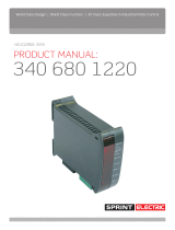
2.1.1 Stator Voltage Control
The Speed / Torque curve for a Slip Ring Motor is shown in the diagram below for the case where the Rotor
resistors are static.
The curved lines represent the Speed / Torque relationship
at 100% and 80% Stator voltage.
The voltage on the Stator is controlled by adjusting the
phase angle of the 3 phase thyristor stack within the JL/X.
This is controlled with reference to the speed setpoint and
speed feedback.
In this case it is possible to alter the speed of the motor for a
given load, requiring the same torque, by adjusting the
Stator voltage.
A reduced Stator voltage will reduce the peak torque by
approximately the square of the voltage reduction.
Here a reduction in Stator voltage from 100% to 80% will
reduce the speed from 78% to 63%
2.1.2 Bi-directional control using the JLX
The JL model has a single 3 phase stack with 3 pairs of anti-
parallel thyristors which provide a phase controlled 3 phase
output driving the stator. Thyristor pairs are 1, 2 and 3
The JLX model has 2 further pairs of anti-parallel thyristors (4
and 5) which allow the direction of the stator phase rotation to be
reversed. In this case the stator is driven by thyristor pairs 1, 4
and 5.
This implementation allows all 4 quadrants of speed and torque
to be controlled.

10
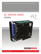
2.1.3 Rotor Control to optimise torque across speed range
The diagram shows all 4 quadrants of speed against torque, with curves for a shorted rotor and for 4 other values of
rotor resistance. This diagram is of course a simplistic representation to facilitate the explanation of the control
strategy.
For a high rotor resistance (R1 + R2 + R3 + R4 + R5) the starting torque is high but the torque at higher speeds
reduces.
For a shorted rotor the starting torque is low but the torque at higher speeds increases.
There is a family of curves in between. The JL/X automatically selects the appropriate Rotor resistance using the
contactor outputs to keep the torque curve at maximum throughout the speed range.
Speed/torque
curve for
shorted rotor
Speed/torque
curve for R1
Speed/torque
curve for
R1 + R2 + R3
Speed/torque curve for
R1 + R2 + R3 + R4
Speed/torque
curve for
R1 + R2
Speed/torque curve for
R1 + R2 + R3 + R4 + R5

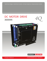
11
Dotted line is
Speed/torque curve for
shorted Rotor
Motoring
forward
quadrant
Braking in
reverse
quadrant
Motoring
reverse
quadrant
Braking in
forward
quadrant
Zero slip hence zero torque at
synchronous speed point.
Dotted line is
Speed/torque
curve for
shorted rotor
Motor speed is higher than synchronous speed hence regenerative current is created by slip
and returned to the supply by the JLX. The braking torque is optimised for the lowest slip by
using a shorted rotor. The maximum torque depends primarily on the overload limit of the JLX
and also the motor/installation rating. The speed will rise above synchronous speed until the
torque reaches a level that satisfies the load.
This action is mirrored in the braking forward quadrant under similar conditions.
The shaded area
is the zone where
regeneration to
the supply occurs
The shaded area is the zone where
regeneration to the supply occurs
Dotted line is
Speed/torque
curve for
shorted rotor
Dotted line is
Speed/torque
curve for
shorted rotor
Speed axis
Torque axis
Forward motor speed
when regenerating
Reverse motor speed
when regenerating
Synchronous
speed point.
2.1.4 Hyper-synchronous regeneration
The shaded areas in the braking quadrants are where regeneration can occur. Outside the shaded areas any
braking that occurs is achieved through a process known as plugging in which the absorbed energy is dissipated in
the rotor and the rotor resistors. Hence for regeneration to occur the load must be forcing the speed to exceed
synchronous speed. The JLX must arrange for the correct loop conditions and thyristor combination to be selected
to regenerate the current back into the supply. As the motor approaches the synchronous speed in either of the
motoring quadrants, the opposing stator phase rotation is selected to activate the braking quadrant. Simultaneously
the speed demand is set above synchronous speed to ensure that the motor speed exceeds the synchronous
speed allowing slip to create regenerative current.

12
2.2 Notes on configuration and the use of this manual
The JL/X has been developed as a special application based on existing PL/X dc drive hardware and software. The
PL/X drive is very versatile, and highly configurable with regards to its internal block diagram connections. In
contrast, the JL/X is pre-configured for the most common slip ring motor applications and in the majority of cases
block diagram connection changes will not be required. The JL/X also makes extensive use of existing PL/X family
application blocks, and most of the available I/O capabilities of the hardware. Therefore this manual does not
include references to the methods required for making block diagram configuration changes or the full functionality
of the individual applications blocks used, just the individual parameters requiring adjustment.
This manual is intended to describe the functionality of the JL/X. For those users wishing to retain existing stator
thyristor power stacks and associated power electronics the JLXD stack driver is also available. However
additional connections must be made, please refer to section 5.9 Notes for users of the JLXD stack driver.
The author welcomes notification of errors or omissions. Please contact jrl@sprint-electric.com with your comments
or suggestions.
2.3 Notes on the use of the JL/X MMI
Similarly, and dependant on the JL/X software issue, certain parameters available when using the JL/X MMI may be
presented using legacy names applicable to the PL/X range of dc drives. In those cases, the parameter names may
be ignored – use the parameter identification numbers for identification purposes if required. This manual does not
describe the internal menu structure of the JL/X.
Reference can be made to the PL/X family manuals for information on both the above subjects and all manuals are
available for download from www.sprint-electric.com if required.
It is strongly suggested that the JL/X should be commissioned using Savvy software rather than via the JL/X MMI
or by using Pilot software (except where noted in the commissioning guide below). Savvy software can be
downloaded from www.driveweb.com by using the “get savvy” link, if required.
3 Control terminals
3.1 Control terminals electrical specifications
The following describes the electrical specification of the control terminals. The default functions for these terminals
are described in section 3.2.
3.1.1 Universal Inputs (UIP2 – UIP9, terminals 2 to 9)
4 input voltage ranges +/-5/10/20/30V.
Input impedance 100K for input scaling at 5 and 10V range.
Input impedance 50K for input scaling above 10V range.
3.1.2 Analogue Outputs (AOP1 – AOP3, terminals 10 to 12)
Short circuit protection to 0V.
Output current +/-5mA maximum.
Output range 0 to +/-11V.
3.1.3 Digital Inputs (DIP1 – DIP4, terminals 14 to 17)

13
Fixed threshold, logic low <2V, logic high >4V.
Input impedance 10K Ohms.
DIP3 and DIP4 may also be used for incremental encoder A and B signals, maximum input frequency 100 KHz.
3.1.4 Digital Input/Outputs (DIO1 – DIO4, terminals 18 to 21)
Input impedance 10K Ohms.
Short circuit protected with internal flywheel diode. (Range 22 to 32 Volts for output high).
Output capability 350mA, total for all digital outputs 350mA.
3.1.5 Digital Outputs (DOP1 – DOP3, terminals 22 to 24)
Short circuit protected with internal flywheel diode. (Range 22 to 32 Volts for output high).
Output capability 350mA, total for all digital outputs 350mA.

14
3.2 Control terminals default functions
When the JL/X is shipped the control terminals are allocated with the following functions. All the programmable
terminals are available to be configured for an alternative function by the user if desired. An alternative joystick
control configuration is stored in recipe page 3. To access it a 3-Key reset is required.
Current versions of the product cannot be reset to “as shipped” default configuration. Please contact the supplier if a
return to default condition is required.
3.2.1 Universal Inputs UIP2 – UIP9 (terminals 2 to 9)
0V terminal 0V T1
Contactor interlock Digital input UIP2 T2
Used by the default configuration as part of the brake release sequencing
Current limit Analogue input UIP3 T3
0 to +10V linear input for 0 to 150% stator current limit (0 to +/-250% on HD models).
Speed demand Analogue input UIP4 T4
0 to +/-10V linear input for 0 to+/-100% speed.
Start positive Digital input UIP5 T5
Used as an alternative START command, setting the polarity of UIP4 to be non-inverting.
Start negative Digital input UIP6 T6
Used as an alternative START command, setting the polarity of UIP4 to be inverting.
Spare input Analogue input UIP7 T7
Positive hyper-synchronous detection input Analogue input UIP8 T8
Link to terminal AOP2 T11 to enable hyper-synchronous speed detection.
Negative hyper-synchronous detection input Analogue input UIP9 T9
Link to terminal AOP2 T11 to enable hyper-synchronous speed detection.
3.2.2 Analogue Outputs AOP1 – AOP3 (terminals 10 to 12) and Iarm (terminal 29)
Stator current % monitor Analogue output AOP1 T10
0 to +/-10V linear output for 0 to+/-150% stator current (or 0 to +/-250% on HD models).
Speed feedback monitor Analogue output AOP2 T11
0 to +/-10V linear output for 0 to +/-100% speed feedback.
Stator voltage % monitor Analogue output AOP3 T12
0 to 10V linear output for 0 to 100% stator rms volts.
3.2.3 Digital Inputs DIP1 – DIP4 (terminals 14 to 17)
0V 0V T13
Connect to clean earth star point.
Spare input Logic low below 2V, high above 4V Digital input DIP1 T14
Spare input Logic low below 2V, high above 4V Digital input DIP2 T15
Encoder (B train or sign) Logic low below 2V, high above 4V Digital input DIP3 T16
Encoder (A train) Logic low below 2V, high above 4V Digital input DIP4 T17

15
3.2.4 Digital Input/Outputs DIO1 – DIO4 (terminals 18 to 21)
Rotor resistor control Digital output DIO1 T18
Output high to control highest rotor resistor shorting contactor.
Rotor resistor control Digital output DIO2 T19
Output high to control second highest rotor resistor shorting contactor.
Rotor resistor control Digital output DIO3 T20
Output high to control third highest rotor resistor shorting contactor
Rotor resistor control Digital output DIO4 T21
Output high to control lowest rotor resistor shorting contactor.
3.2.5 Digital Outputs DOP1 – DOP3 (terminals 22 to 24)
Brake engage Digital output DOP1 T22
Output low to demand brake engage when stopping – rotor speed threshold activated.
Brake release Digital output DOP2 T23
Output high to authorise brake release when starting – stator current threshold activated.
Drive healthy Digital output DOP3 T24
Output high when the controller is healthy.
3.3 Non-programmable terminals (terminals 25 to 53)
3.3.1 Control board terminals
Analogue 0V A0V T25
Analogue tacho input TACHO T26
+/- 200V range, input impedance 150K Ohms
+10V reference output +10 T27
+10.00V +/-0.5%, 10mA max. Short circuit protection to A0V
-10V reference output -10 T28
-10.00V +/-0.5%, 10mA max. Short circuit protection to A0V
Stator current metering output Iarm T29
+/-5V +/-5% linear output for +/-100% model rating stator current
Programmable uni-polar or bi-polar output
Output current capability 10mA. Short circuit protection to A0V
Thermistor input THERM T30
Motor temperature thermistor or thermal switch
OK<200 Ohms, Over-temperature >2K Ohms. Connect between THERM and A0V
Run input RUN T31
Electronic enable for current loop and contactor drop out delays
24V logic input, logic low <6V, logic high >16V
Input impedance. 10K Ohms
Brake fail assist input JOG T32
Jog input with programmable contactor drop out delay
24V logic input, logic low <6V, logic high >16V
Input impedance. 10K Ohms

16
Start input START T33
Start input with programmable contactor drop out delay.
24V logic input, logic low <6V, logic high >16V.
Input impedance 10K Ohms.
Coast stop input CSTOP T34
Coast stop input.
24V logic input, logic low <6V, logic high >16V.
Input impedance 10K Ohms.
+24V +24 T35
Nominal +24V output for external logic, range 22 to 34 volts.
Short circuit protected.
Shares total current capability of ‘Digital Outputs’ (350mA), with additional 50mA capability.
Total maximum available 400mA.
WARNING. Do not rely on any JL/X function to prevent the motor from operating when personnel are
undertaking maintenance, or when machine guards are open. Electronic control is not accepted by safety
codes to be the sole means of inhibition of the controller. Always isolate the power source before working
on the JL/X or the motor or load. If the RUN input goes low at any point during the stopping process then
the contactor will drop out straight away.
3.3.2 Power board terminals
RA+ RA+ T41
Not used on the JL/X.
Also refer to section 5.9 Notes for users of the JLXD stack driver
NC NC T42
Do not connect to this terminal.
RA- RA- T43
Not used on the JL/X.
Also refer to section 5.9 Notes for users of the JLXD stack driver
NC NC T44
Do not connect to this terminal.
CON1 CON1 T45
Rating up to 240V 500VA.
Volt free contact for controlling main supply contactor coil.
CON2 CON2 T46
Rating up to 240V 500VA.
Volt free contact for controlling main supply contactor coil
LATCH1 LATCH1 T47
Connect to UIP2, terminal 2
LATCH2 LATCH2 T48
Connect to 24V, terminal 35
E E T51
Dirty earth connection for control supply
N N T52
Control supply neutral connection
100-240VAC, 50/60Hz +/-10% 50VA

17
L L T53
Control supply line connection
100-240V 50/60Hz +/-10% 50VA
4 Rating Tables
4.1 Rating Table for JL/X standard duty versions
These models have a 150% overload capability for 25 seconds
Nominal maximum continuous ratings
Model
KW at
415V
AC
HP at
415V
AC
HP at
480V
AC
HP at
690V
AC (HV
models)
100%
Output
Current
Cooling air
flow and
dissipation
cfm watts
Dimensions mm
W x H x D
JL/X130
75
100
115
N/A
130
365
380
216 x 378 x 218
JL/X170
100
130
150
N/A
170
365
500
216 x 378 x 218
JL/X220
130
170
200
N/A
220
365
650
216 x 378 x 218
JL/X270
160
210
240
N/A
270
365
875
216 x 378 x 218
JL/X370
215
290
335
480
370
400
1200
253 x 700 x 350
JL/X450
260
350
405
580
450
400
1450
253 x 700 x 350
JL/X530
310
415
480
690
530
400
1700
253 x 700 x 350
JL/X615
360
480
555
800
615
400
2000
253 x 700 x 350
JL/X700
405
550
630
915
700
400
2300
253 x 700 x 350
JL/X780
450
610
705
1015
780
400
2500
253 x 700 x 350
JL/X860
500
670
775
1115
860
800
2700
506 x 700 x 350
JL/X1025
595
800
925
1330
1025
800
3200
506 x 700 x 350
JL/X1190
690
930
1075
1550
1190
800
3700
506 x 700 x 350
JL/X1350
785
1055
1220
1755
1350
800
4200
506 x 700 x 350
JL/X1520
880
1190
1375
1980
1520
800
4700
506 x 700 x 350
JL/X1680
975
1310
1515
2180
1680
800
5200
506 x 700 x 350

18
4.2 Rating Table for JL/XHD high duty versions
These models have a 250% overload capability for 25 seconds
Nominal maximum continuous shaft ratings
Model
KW at
415V
AC
HP at
415V
AC
HP at
480V
AC
HP
690V
AC (HV
models)
100%
Output
Current
A rms
Cooling air
flow and
dissipation
cfm watts
Dimensions mm
W x H x D
JL/XHD75
45
60
70
N/A
75
365
380
216 x 378 x 218
JL/XHD100
60
80
90
N/A
100
365
500
216 x 378 x 218
JL/XHD130
75
100
115
N/A
130
365
650
216 x 378 x 218
JL/XHD160
95
125
145
N/A
160
365
875
216 x 378 x 218
JL/XHD220
130
170
200
280
220
400
1200
253 x 700 x 350
JL/XHD270
160
210
240
350
270
400
1450
253 x 700 x 350
JL/XHD320
190
250
290
415
320
400
1700
253 x 700 x 350
JL/XHD370
215
290
335
480
370
400
2000
253 x 700 x 350
JL/XHD420
245
330
380
550
420
400
2300
253 x 700 x 350
JL/XHD470
270
370
430
615
470
400
2500
253 x 700 x 350
JL/XHD520
300
405
470
670
520
800
2700
506 x 700 x 350
JL/XHD615
360
480
555
800
615
800
3200
506 x 700 x 350
JL/XHD715
415
560
650
930
715
800
3700
506 x 700 x 350
JL/XHD815
475
640
740
1065
815
800
4200
506 x 700 x 350
JL/XHD910
530
710
820
1180
910
800
4700
506 x 700 x 350
JL/XHD1010
585
790
915
1310
1010
800
5200
506 x 700 x 350
365 cubic feet per minute is approximately equivalent to 11 cubic metres per minute.
400 cubic feet per minute is approximately equivalent to 12 cubic metres per minute.
800 cubic feet per minute is approximately equivalent to 24 cubic metres per minute.
Standard Models
Main 3 phase supply 50 – 60Hz Any supply from 12 to 480V AC +/- 10%
Auxiliary 3 phase supply 50 – 60Hz Any supply from 100 to 480V AC +/- 10%
Control 1 phase (50VA) 50 – 60Hz Any supply from 110 to 240V AC+/- 10%
High Voltage (HV) Models
Main 3 phase supply 50 – 60Hz Any supply from 12 to 690V AC +/- 10%
Auxiliary 3 phase supply 50 – 60Hz Any supply from 100 to 690V AC +/- 10%
Control 1 phase (50VA) 50 – 60Hz Any supply from 110 to 240V AC+/- 10%
Internal Fan supply
JL/X 370/450/530/615/700/780/860 models also need a separate 100VA 240V 50/60Hz ac fan supply.
JL/X 860/1025/1190/1350/1520/1680 models need a 200VA 240V 50/60Hz ac fan supply.
OUTPUT VOLTAGE RANGE
U, V, W 0 to 1.0 times AC supply.
OUTPUT CURRENT RANGE
Standard models 0 to 100% continuous, 150% for 25 seconds
HD models 0 to 100% continuous, 250% for 25 seconds

19
4.3 Environment ratings
Temperature: 0 – 40
O
C ambient enclosure internal operating temperature
(0 – 35
O
C for JL/X1680 and JL/XHD1010)
-25
O
C - +55
O
C storage
Protect from direct sunlight
Ensure dry, corrosive free environment
85% relative humidity maximum
Non-flammable, non-condensing
Pollution degree: 2
Installation category: 3
Short circuit-rating: Suitable for use on a circuit capable of delivering not more than
18000A (JL/X130 – 270 and JL/XHD75 – 160),
42000A (JL/X370 – 780 and JL/XHD220 – 470),
85000A (JL/X860 – 1680 and JL/XHD520 – 1010),
85000A (JL/X370HV – 780HV and JL/XHD220HV – 470HV),
100000A (JL/X860HV – 1680HV and JL/XHD520HV – 1010HV)
RMS symmetrical amperes when protected by Ar class fuses.

20
L1 L2 L3
U V W
Stator
E
Line reactor
Supply contactor
EL1
EL2
EL3
45
46
53
51
52
Coil supply
Control supply
Semiconductor fusing
Main incoming three phase supply
(branch protected, see manual fusing detail)
Auxiliary contact
31
35
Fan supply (model dependent,
see terminal description)
B1
B2
Note: EL1,2,3 terminal wiring, control supply
and coil supply breaker or HRC fuse protected
5 Basic wiring diagrams
Please note: The following diagrams indicate the simplest possible configurations, utilise functions found in the
default block diagrams and are thus not exhaustive. Alternative control strategies are possible as the JL/X is fully
configurable.
5.1 Basic power control diagram
/