Page is loading ...

World Class Design | World Class Function | 30 Years Expertise In Industrial Motor Control
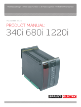
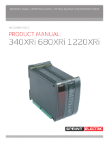
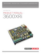
PRODUCT MANUAL:
HG102908 ISS9
340 680 1220

Model 340 / 680 / 1220 DC drive product manual 1
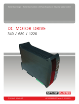
INSTALLATION
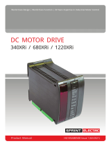
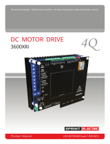
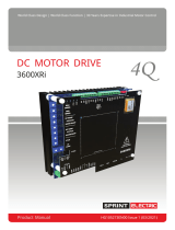
340 / 680 / 1220
DC Motor Controller
Product Manual
This drive is a speed controller for shunt
wound or permanent magnet motors. It utilises speed feedback from the armature voltage, or from a shaft
mounted tachogenerator. It incorporates an accurate current control loop to protect the drive and motor. The
unit is a non-isolated component. Please obtain expert help if you are not qualified to install this equipment.
Make safety a priority. This component is hazardous. (All specifications in this document are nominal).
340 0.55KW (0.5 HP) at 180 Volts DC
680 0.75KW (1.0 HP) at 180 Volts DC
1220 1.8KW (2.0 HP) at 180 Volts DC
(The KW / HP ratings are typical motor ratings at or below the available terminal rating of Watts= AV x IA)
Versions that work from 60V / 30V AC supply are also available.
340 / LV60, 680 / LV60, 1220 / LV60. For motors rated up to 48V DC
Armature: 200 Volts DC. 48V DC for LV60 models
Models 340 / 680 / 1220 --- 3.4 / 6.8 / 12.2 Amps.
Field: Volts DC= 0.9 x AC supply volts. 1 Amp
(0.45 x AC for field connected to F- and N). 1 Amp.
110V AC or 240V AC +/-10%, 50–60 Hz.
30V AC or 60V AC +/-10%, 50-60Hz for LV60 models.
Speed range 0–100%. (motor dependant)
Load Regulation typically 0.2% tach, 2% Arm Volts.
Presets accessible under lift up cover.
Clockwise rotation for linear increase in parameter
Maximum Speed (Max spd) 40 to 200V (armature volts or tach feedback volts)
LV60 models have an Avf range 10 - 50V.
Minimum Speed (Min spd) 0 to 30% of maximum speed
Ramp (Ramp) 20 to 1 seconds up ramp rate
IR compensation (IR comp) 0 to 30%
Max Current (I max) 0 to 100% current limit.
Speed setpoint from external 10K Ohms pot.
External RUN contact for electronic STOP/START
There is a pot kit including graduated dial and knob. Sprint Electric part number. POTKIT.
Speed loop: Full P+I armature voltage or tach feedback.
Current loop: Full P+I current shunt feedback.
Use correctly rated cable minimum 600V AC, 1.5 times armature current.
DOC# HG102908 iss9 06/07/17
POWER RATING
MAXIMUM OUTPUT
AC SUPPLY INPUT
SPEED RANGE
USER ADJUSTMENTS
EXTERNAL CONTROLS
CONTROL ACTION

2 Model 340 / 680 / 1220 DC drive product manual
FUSING REQUIREMENT
MECHANICAL
To avoid damage, ensure the supply selection jumper on the drive
matches the incoming supply. 110V or 240V AC.
For models with LV60 suffix 30V AC or 60V AC.
Semi-conductor fuse parts.
20A fuse (BUSSMANN FWH020A6F) CH00620A
Fuseholder 6 X 32mm CP102071
DIN rail clip for fuseholder FE101969
Suitable for use on a circuit capable of delivering not more than 5000A RMS symmetrical amperes when protected
by an aR class fuse.
WARNING Protection must be provided by a correctly rated semi-conductor fuse, in the AC supply to the
drive. The fuse must have an I
2
t rating of less than 150 A
2
s.
To satisfy UL requirements for branch circuit short-circuit protection the fuse must be as specified above.
The control signals are NOT isolated from the AC supply. Do not connect
them to other instruments.
The unit is designed to clip onto a DIN rail. Avoid vibration and ambient
temperatures outside –10 and +40C. Protect the unit from pollutants.
Ensure there is an adequate supply of clean cool air to ventilate the unit
and the enclosure it is mounted in. (Dissipation in Watts = 5 x Armature Amps).
Foot mounted motors must be level and secure. Protect motors from
ingress of foreign matter during installation. Ensure accurate alignment
of motor shaft with couplings. Do not hammer pulleys or couplings onto
the motor shaft.
Before running motor, complete the following check list. (Warning isolate the supply first).
1) Correct insulation between all motor windings and earth. (Disconnect all drive cables prior to testing).
2) Check inside connection box for foreign objects, damaged terminals etc.
3) Check that brushes are in good condition, correctly seated and free to move in brush boxes.
Check correct action of brush springs.
4) Motor vents must be freed of any obstruction or protective covers prior to running.
5) WARNING for reversing systems. To prevent damage do not transpose the armature connections until the
motor has stopped rotating.
Please note this drive does not provide motor over-temperature protection. If required, equip your motor
with an external thermal sensor device that can remove the supply when activated by over-temperature.
Set the CURRENT preset to approximately match the motor armature
rating. Fully clockwise is 100% drive rating. (340
3.4A, 680 6.8A, 1220 12.2A). Fully anticlockwise is 0%. E. g. for a 340 unit
a midway setting is 50% ie 1.7A. More accurate setting requires a suitable current meter in series with the
armature.
Set all the other presets anticlockwise to start off with.
The preferred strategy for initial commissioning is in armature voltage feedback mode described as follows. Set
Avf/tach switch ON (left) for armature voltage feedback (AVF) and Spd x 2 switch OFF (right) for 50V max
feedback. For systems utilising tach feedback, remove the terminal 6 tach connection.
PRESET POT settings
CONTROL SIGNALS
MOTOR
AC SUPPLY

Model 340 / 680 / 1220 DC drive product manual 3
Check that the Power lamp lights. Increase the external speed pot
slowly maximum. The motor should slowly ramp up to around 40V on the
motor armature. If the system is to rely on armature voltage feedback you can now set the correct armature
voltage and hence speed by using Spd x 2 switch and the Max spd preset (Clockwise to increase speed).
The up ramp rate can now be set between 20 and 1 seconds. And the Min
spd adjusted up to 30%.
Speed droop on heavy loads may occur where armature voltage feedback
is used. This is compensated for by clockwise rotation of IR comp.
Excessive rotation may lead to instability.
IR Comp is not used with tach feedback, leave preset anticlockwise.
With tach feedback it is necessary for the polarity to be negative on
terminal 6 with respect to terminal 4, and
Avf/tach switch OFF (right). Calculate the maximum feedback voltage
from the tach and adjust Spd x 2 switch and Max spd to give the correct speed. ( With Spd x 2 switch OFF (right)
Max spd range = 40 to 100V. For Spd x 2 switch ON (left) range = 90 to 200V).
WARNING. All terminals are at high potential.
DO NOT TOUCH the terminals or any connected conductor.
1 +10V output. 2mA max. (Use a 10K Ohm pot for external speed reference).
2 MIN SPEED. (Connect to minimum end of external speed pot. 5K Ohms preset to common).
3 SPEED INPUT. 0 to +10V speed input from pot wiper. 39K internal pull down.
4 COMMON.
5 RUN. Internal 12K pull up to 12V. Open to stop, close to COMMON to run. WARNING. RUN is an
electronic inhibit function. The field remains energised, and all power terminals ‘live’. RUN must
not be relied on during hazardous operations.
6 TACH input. The tach feedback must be negative with respect to COMMON.
A+ Motor armature + Typical form factor 1.5 (load dependant).
A- Motor armature -
F- Motor Field – (No connection required for permanent magnet motors).
F+ Motor Field + (For half wave field volts 0.45 X AC, connect field to F- and N).
N AC supply
L AC supply
Terminal tightening torque 4.4in lb - 0.50Nm
Models 680 and 1220 use an internal fan for cooling. The Alarm lamp will
come ON and the drive will electronically shut down if the internal fan
fails. The field will remain energised, hence if the machine is to be left
unattended for long periods it may cause the field to overheat. There is a pair of solder pads adjacent to
Terminal 6. If they are linked then the ALARM is inhibited. The unit may be run at currents below 3 Amps without
a fan.
For frequent stopping or jogging it is recommended to use T5 RUN input.
If you use a mains contactor then connect a spare Normally Open contact
on the contactor in series with the RUN input.
In armature voltage feedback the tach input terminal 6 may used a
as an auxiliary fast +/- speed trim. (approx 5 -10%)
POWER ON
RAMP and MIN SPEED
IR COMP
TACH FEEDBACK
TERMINAL LISTING
ALARM
JOGGING
AUXILIARY INPUT

4 Model 340 / 680 / 1220 DC drive product manual
The product is enclosed in a stylish DIN rail mounted enclosure with plug
in screw terminal connections.
.
Height
Width
Depth
340
105
35
120
680
105
45
120
1220
105
45
120
Earthing The terminals are
non-isolated hence do not earth.
The motor earth should be connected
to the system enclosure earth.
WARNING. This product is non-isolated hence all terminals are at dangerous line potential. Ensure connected
items (e.g. speed pot, tach etc.) are not earthed and have sufficient dielectric strength to avoid breakdown.
Do not touch any part of the unit. Use an insulated tool to adjust the presets. Do not touch when unit is ON.
If the unit is to be used in the domestic environment then for
installations in the EU a supply filter is recommended in order to
comply with EN6800-3. Sprint Electric part number FRLN16. For
installation guidelines on wiring for compliance with EU EMC regulations please refer to the Sprint Electric
website at www.sprint-electric.com and then ‘Downloads’, ‘Technical Data’.
Health and safety at work. Electrical devices constitute a safety
hazard. It is the responsibility of the user to ensure
compliance with any acts or bylaws in force. Only skilled persons
should install this equipment. Sprint Electric Ltd. does not accept any liability whatsoever for the
installation, fitness for purpose or application of its products. It is the users responsibility to ensure the unit
is correctly used and installed.
This apparatus complies with the protection requirements of the
relevant EU directives.
UL file E168302
MECHANICAL DETAILS
Supply Select
Power lamp
Sw 1 AVF/Tach
Sw 2 Spd x 2
Max Speed
Min Speed
Ramp
IR Comp
Max Current
Alarm lamp
Lift up cover
T1 T2 T3 T4 T5 T6
+10 Min IP Com Run Tach
A+ A- F- F+ N L
Fan
exhaust
Armature
Field
DIN rail
release catch
with bottom
rear access
slot. (Unplug
terminals to
gain access)
EMC WIRING GUIDE
WARNINGS
Sprint Electric Limited, Arundel,
UK
Tel. +44 (0)1243 558080
Fax. +44 (0)1243 558099
Email. [email protected]
www.sprint-electric.com
APPROVALS

Find out more:
www.sprint-electric.com
Sprint Electric Ltd. Peregrine House, Ford Lane, Ford
Arundel, West Sussex, BN18 0DF United Kingdom
Tel: +44 (0)1243 558080
Fax: +44 (0)1243 558099
Email: [email protected]
/