Page is loading ...

World Class Design | World Class Function | 30 Years Expertise In Industrial Motor Control
PRODUCT MANUAL:
HG103684 ISS2
400XLV 800XLV
1200XLV

400XLV/800XLV/1200XLV Product Manual
Contents
1 Description ............................................................................................ 3
2 Safety information................................................................................ 3
3 Connections and LEDs ........................................................................ 4
4 Block diagram ..................................................................................... 5
5 Installation ............................................................................................ 5
5.1 Wiring and protection .........................................................................5
5.2 DC power supply .................................................................................5
5.3 Mechanical design ..............................................................................5
5.4 Load .......................................................................................................6
5.5 EMC .......................................................................................................6
6 Terminal descriptions .......................................................................... 7
6.1 Power terminals ....................................................................................7
6.2 Control terminals ..................................................................................7
7 Pre-sets and diagnostics .................................................................... 8
8 Commissioning .................................................................................... 9
8.1 Pre-operation Checks .........................................................................9
8.2 Start-up Procedure ........................................................................... 10
8.3 Tacho Commissioning ...................................................................... 10
8.4 Tuning and Optimisation .................................................................. 11
9 Technical specifications ................................................................... 13
10 Applications ....................................................................................... 13
11 Troubleshooting ................................................................................. 15
11.1 Trips and alarms................................................................................. 15
Sprint Electric Ltd accepts no liability whatsoever for the installation,
fitness for purpose or application of its products. It is the user’s
responsibility to ensure the unit is correctly used and installed.
2 HG103684 Issue 2

400XLV/800XLV/1200XLV Product Manual
1 Description
The XLV range of dc servo motor controllers are designed for use with
permanent magnet brushed dc servo motors rated from 4 to 12 amps.
The controllers can be used in either current (torque) or speed control
modes. For highly dynamic applications, a shaft-mounted dc tacho-
generator is recommended for speed feedback, however in less
demanding applications, armature voltage feedback (Avf) can be
used.
The reference signal for both current and speed control can be either
bipolar (±10V) or unipolar (0 – 10V). Motor speed can be controlled in
both forward and reverse directions. An adjustable current limit and
fast-acting current control loop protect the controller and motor from
sustained overloads.
2 Safety information
The XLV servo motor controller operates from a supply voltage of less
than 60V which means there is a very low risk of electric shock if the
user comes into contact with any of the power terminals during
operation. However, the controller is capable of producing high
current which can cause the load motor and associated machinery to
run at high speeds or generate significant heat, or both, if incorrectly
configured.
Electric shock risk! Electrical devices constitute a safety hazard.
It is the responsibility of the user to ensure compliance with any
acts or bylaws in force.
Only install this device if you have the skills and knowledge to
use it safely.
HG103684 Issue 2 3

400XLV/800XLV/1200XLV Product Manual
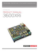
3 Connections and LEDs
Figure 3-1: User connections
Figure 3-2: Power, control and diagnostic connections (under unit)
Figure 3-3: Diagnostic pins (adjacent to control terminals)
Current demand
Current feedback
6 V ref
Power terminals:
dc+, A+, A
-, dc-, GND
Control terminals
1 to 11
Diagnostic pins
(see below)
Zero speed (P9)
DIN rail clip
0 V
Lift-up cover
Maximum speed (P1)
Alarm LED
Current loop P gain (P6)
Speed demand
Power LED
IR comp (P8)
Current limit (P5)
Current loop I term (P7)
Speed loop I term (P4)
Speed loop P term (P3)
Speed scale switch
Speed feedback
Minimum speed (P2)
Zero speed (P9)
4 HG103684 Issue 2

400XLV/800XLV/1200XLV Product Manual
4 Block diagram
Figure 4-1 shows the key function blocks within the controller.
Note: There are two nested control loops – an inner current loop and
an outer speed loop.
Figure 4-1: Block diagram
The RUN switch must be connected to +24 V for the controller to
operate. This is a non-latching input.
5 Installation
5.1 Wiring and protection
Use wire suitable for 1.5 x rated armature current.
The controller must be protected with suitably rated fuses.
5.2 DC power supply
Use a dc power supply appropriate to the voltage rating of the XLV
controller being used (12 Vdc, 24 Vdc, 48 Vdc). It must have a current
rating at least equal to the full load current of the motor.
5.3 Mechanical design
The XLV controller is designed to clip onto a DIN rail.
Do not expose the unit to excessive vibration and ensure that there is
sufficient cooling to keep the ambient temperature below 40 °C.
The maximum dissipation of the controller is 15 watts (1200XLV).
HG103684 Issue 2 5

400XLV/800XLV/1200XLV Product Manual
5.4 Load
The XLV controller is designed to control the armature current and
shaft speed of a permanent magnet dc servo motor. Although the
motor current rating can exceed the current rating of the XLV
controller, operation under these conditions will mean that rated
torque cannot be achieved. Similarly, the armature voltage rating can
exceed the XLV controller voltage but the motor will not be able to run
at rated speed.
It is also possible to use the XLV controller to control the current in other
inductive loads (e.g. linear actuators). This typically means the
controller must be operated in current control mode (see Figure 10-3).
5.5 EMC
According to IEC61800-3 (EN61800-3), the XLV controller is classified as
a Basic Drive Module (BDM) only for installation by professional
assemblers and for use in the second environment. The drive
manufacturer is responsible for the provision of installation guidelines
and the manufacturer of the system is responsible for its EMC
performance.
5.5.1 Power Port
If the system using the XLV controller will operate in the second
environment then a separate filter unit is not normally required.
To meet emissions limits on this port in the first environment, a separate
filter is required.
5.5.2 Earthing and Screening
Connect a separate earth connection from the motor frame to the
main earth terminal on the controller (terminal 5). Do not ground it to
any other earth point.
Connect the drive protective earth on terminal 5 to the star-point earth
in the cabinet.
Segregate the DC power and armature power connections from all
other cables in the cabinet.
Where screened or armoured cables are used for power connections
terminate the screen to earth at both ends of the cable. Only connect
control cables of this type at the drive end.
Safety earthing always takes precedence over EMC earthing.
6 HG103684 Issue 2

400XLV/800XLV/1200XLV Product Manual
6 Terminal descriptions
6.1 Power terminals
Terminal No.
Name
Description
1
dc +
dc supply to controller
2
A +
Positive connection to motor armature
3
A -
Negative connection to motor armature
4
dc -
Common for dc supply to controller
5
GND
Earth
6.2 Control terminals
The control terminals are all referenced to the negative dc supply to
the controller (dc-). All interface signals must be referenced to the
same potential.
Section 10 gives further details about the function of the control
terminals.
Terminal
No.
Name Description
1
+10 V
REF
10 V reference (±0.1%) for terminal 3
(10 mA current limit)
2
MIN SPD
Connection for speed demand pot to set
minimum speed
(input impedance = 5 kΩ)
3
REF IN
Reference for speed/current
(input impedance = 47 kΩ)
4
0 V
Common for reference input
5
+24 V
Supply for driving digital inputs
(50 mA current limit)
6
IMODE
Select current (torque) mode – active high
(input impedance = 110 kΩ)
HG103684 Issue 2 7

400XLV/800XLV/1200XLV Product Manual
Terminal
No.
Name Description
7
FWD
Forward direction select for unipolar
reference – active high
(input impedance = 110 kΩ)
8
REV
Reverse direction select for unipolar
reference – active high
(input impedance = 110 kΩ)
9
RUN
Electronic enable for controller – active high
(input impedance = 110 kΩ)
10
0 V
Common for tacho
11
TACH
DC tacho-generator input (±60 Vdc max)
(input impedance = 150 kΩ)
7 Pre-sets and diagnostics
The following pre-sets (potentiometers) are available for user
adjustment under the translucent red flap on the front of the product.
Pre-set
Description
Max Spd
Sets maximum motor speed (in conjunction with speed
scaling selection switch)
Min Spd
Sets minimum motor speed (0 to 30% of Max Spd setting)
Spd P
Speed loop proportional gain
Spd I
Speed loop integral time constant
I max
Current limit
Cur P
Current loop proportional gain
Cur I
Current loop integral time constant
IR comp
Compensation for IR drop in motor when running with Avf
(0 to 25% of max armature voltage)
8 HG103684 Issue 2

400XLV/800XLV/1200XLV Product Manual
All potentiometers are factory-set to a ‘safe’ condition. This means the
gains are at minimum setting.
Note: The current limit is set at approximately 100%.
There is an additional potentiometer, located adjacent to the
diagnostic pins, which can be used to adjust the motor speed to zero
when the speed reference is 0 V. This prevents shaft “creep” at zero
speed.
A switch, located adjacent to the pre-set potentiometers, provides two
functions:
• Function 1: Select Speed Feedback Source:
S1 ON Avf speed control
S1 OFF Tacho speed control
• Function 2: Select Speed Feedback Scaling:
S2 ON VA range = 10 – 25 Vdc; Tacho range = 12 – 30 Vdc
S2 OFF VA range = 20 – 50 Vdc; Tacho range = 24 – 60 Vdc
Two LEDs are provided for diagnostic purposes:
• Power LED: indicates that DC power is applied to the unit and the
internal power supply is operational.
• Alarm LED: indicates the presence of an internal fault or trip.
Note: Section 11.1 gives further details on the possible causes of
internal trips.
8 Commissioning
Commission the controller with the motor decoupled from the load. If
this is not possible, exercise additional caution in the commissioning
process to ensure the load is not damaged as a result of the motor
rotating in the wrong direction, excessive speed or high vibration from
a poorly tuned speed loop.
8.1 Pre-operation Checks
Before applying power to the controller, check the following:
• The dc supply voltage is correct.
• The motor rating (armature current and voltage) is within the rating
of the controller.
• All power and control connections are securely made.
HG103684 Issue 2 9

400XLV/800XLV/1200XLV Product Manual
• All pre-sets are in their default position (P1, P2, P3, P6 and P8
counter-clockwise, P4 and P7 clockwise and P5 mid-range).
Apply the power. Confirm the following:
• The Power LED illuminates.
• No RUN signal is present (terminal T9 is open-circuit).
• The armature voltage feedback (Avf) is selected as the speed
feedback source (Avf/Tach switch ON), even if a tacho-generator
will ultimately be used for this purpose.
• Select x1 scaling for maximum speed. This will limit the armature
voltage to 25V.
8.2 Start-up Procedure
The next stage in the commissioning process is to run the motor with
armature voltage feedback.
1 Apply a positive speed reference of around 10% (1V) to terminal T3.
2 Connect the RUN terminal (T9) to +24 V.
3 Check that the motor is running smoothly in the direction required
for a positive speed reference.
8.3 Tacho Commissioning
Operating with tacho speed feedback gives superior dynamic
performance and is recommended for all high bandwidth
applications.
To commission a motor with tacho feedback, follow the procedure
below:
1 Connect one of the tacho wires to terminal T10.
2 Run the motor using the procedure detailed in section 8.2 above.
3 With the motor running measure the voltage on the other tacho
wire.
4 If this voltage has the opposite polarity to the voltage on terminal
T3, stop the motor, disconnect the power to the controller and
connect the wire into terminal T11.
5 If the voltage is the same polarity then disconnect the power to
the controller and reverse the two tacho wires.
6 Turn the Avf/Tach switch OFF.
7 Power the controller on.
8 Re-start the motor.
9 Check that the motor is running smoothly in the direction required
for a positive speed reference.
10 HG103684 Issue 2

400XLV/800XLV/1200XLV Product Manual
Note A rectified AC tacho cannot be used with the XLV controller.
8.4 Tuning and Optimisation
8.4.1 Maximum Speed Setting
Whether running with tacho or Avf, this pre-set is used to set the
maximum speed of the motor using the procedure below:
1 Set the speed reference to maximum (+10 V) on terminal T3
2 If running with Avf, measure the voltage on terminals A+, A- and
increase the Max Spd potentiometer until the measured armature
voltage is equal to that stated on the motor nameplate.
Note: If the motor’s rated armature voltage exceeds 25 V the Spd
x2 switch should be set to the OFF position.
3 If running with tacho feedback, increase the Max Spd potentiometer
until the voltage measured across terminals T10 and T11 equals the
full speed tacho voltage.
Note: If the maximum tacho voltage exceeds 30 V, the Spd x2
switch should be set to the OFF position.
Avoid changing the position of the Spd x2 switch whilst the motor is
running as this will result in a step speed change.
8.4.2 Minimum Speed Setting
With a 10 kΩ potentiometer connected between terminal T1 and T2
and its wiper connected to terminal T3 the minimum speed can be
adjusted with the Min Spd pre-set. This connection is shown in section 4.
By increasing the Min Spd potentiometer (rotate CW), the minimum
speed can be adjusted up to a maximum of 30% of maximum speed.
8.4.3 Current Limit Adjustment
The current limit pre-set I max is used to adjust the maximum motor
current of the controller:
• With the pot fully counter-clockwise the current limit is 0% and the
motor will not run.
• With the pot at mid-position the full current of the controller is
available continuously (4 amps for 400XLV).
• With the pot fully clockwise the controller will deliver 200% of its
rating for one second (8 amps for a 400XLV).
When the overload capability of the controller is used, the current limit
automatically reduces to 100% to protect the controller and the motor.
HG103684 Issue 2 11

400XLV/800XLV/1200XLV Product Manual
With I max pre-set fully CW, the controller will deliver 200% current for
one second and will then reduce its output to 100% within 5 seconds.
8.4.4 IR Compensation
One of the limitations of armature voltage feedback as a method for
controlling motor speed is that when under load, Avf is no longer
directly proportional to motor speed. To compensate for the effect of
load, the IR comp pre-set should be adjusted using the following
procedure:
1 Run the motor at full speed and monitor the armature voltage.
2 When the motor is fully loaded, increase the IR comp pre-set
(rotate CW) until the armature voltage matches the nameplate
value.
Note: Setting the IR comp pre-set excessively high can result in
speed instability.
8.4.5 Control Loop Tuning
The XLV controller has two nested control loops: an inner current loop
and an outer speed loop. Both use PI (proportional-integral)
compensators which each have independent control of the P and I
terms.
The controller will function well with the P and I pre-sets in the default
position (i.e. CCW for P terms and CW for I terms) but performance
may be optimised by adjusting them.
Guidance for tuning the control loops is given below:
1 First optimise the current control loop.
2 Apply small step load changes and increase the proportional gain
(Cur P) to improve the speed of response, taking care not to make
the current loop unstable.
3 Reduce the integral time constant (Cur I) to reduce over-shoot
and settling time.
4 Now optimise the speed loop by applying small step changes to
the speed reference and adjusting Spd P and Spd I using the same
criteria as for the current loop tuning.
Diagnostic pins are available for monitoring speed and current
demand and feedback via an oscilloscope. These are located next to
the control terminals on the underside of the unit.
Note: The demand and feedback signals have opposite polarities
and are scaled as follows:
12 HG103684 Issue 2

400XLV/800XLV/1200XLV Product Manual
Speed: 10V = 100%, 6V = 0%, 2V = -100%
Current: 10V = 200%, 6V = 0%, 2V = -200%
8.4.6 Zero Speed Adjustment
Potentiometer P9 (adjacent to diagnostic pins) provides adjustment to
ensure the motor is stationary with a speed reference of zero.
9 Technical specifications
Motor current
4 A (400XLV)
8 A (800XLV)
12 A (1200 XLV)
Overload
200% for one second (inverse time
reduction to 100% in 5 seconds).
Supply voltage variants
12 V dc
(± 5%)
24 V dc
(± 10%)
48 V dc
(± 10%)
Operating temperature
0 to 40 °C
Dimensions (H x W x D)
400XLV
800XLV
1200 XLV
105 x 60 x 120 mm
105 x 60 x 120 mm
105 x 70 x 120 mm
10 Applications
The following diagrams show the basic wiring requirements for the XLV
controller in different applications.
Note: Protection circuitry (fusing, motor over-speed, motor over-
temperature) are omitted as they will depend on the
particular risks identified in the end application.
HG103684 Issue 2 13

400XLV/800XLV/1200XLV Product Manual
Figure 10-1: Bi-directional speed control with bipolar reference
This configuration would typically be used when an external controller
(e.g. a positioning system) provides the speed reference.
Figure 10-2: Bi-directional speed control with unipolar reference
Note: The switches for forward and reverse running do not need to be
latching as this function is within the controller.
Figure 10-3: Unipolar current control
This configuration can be used for non-motor loads requiring current
control (e.g. linear actuators). If operating a motor in this configuration,
include measures to limit motor speed under light-load conditions.
14 HG103684 Issue 2

400XLV/800XLV/1200XLV Product Manual
11 Troubleshooting
11.1 Trips and alarms
Controller trips may occur during commissioning and normal operation
resulting in the controller stopping and the Alarm LED illuminating. The
trips that can result in an alarm state are listed below.
Note: There is no motor over-temperature trip. To protect the motor
from over-heating a thermal protection device attached to
the motor must be inter-locked with the dc supply to the
controller.
Note: When any trip occurs, switch the RUN signal on terminal T9 ON
to OFF and then back to ON again to re-start the controller.
If the trip condition persists, it is not possible to re-start the
controller. Remove the controller from the system and return it
to Sprint Electric Ltd.
11.1.1 Armature over-current (OVERI) trip
The controller will trip on this alarm if the instantaneous current exceeds
250% of the current rating of the particular model. For example, a 4 A
400XLV has a trip current of 10 amps. Typically an OVERI trip occurs
when too much proportional gain has been applied to the current
loop, when operating at high currents (rapid speed transients and high
loads), or less frequently because of a motor fault.
An OVERI trip is characterised by the controller stopping immediately
when there has been a large speed or load change. It re-starts
immediately.
To remedy an OVERI trip:
• Adjust P6 to tune the current loop proportional gain.
• Disconnect the motor and re-start the controller. If it no longer trips
then check the integrity of the motor and wiring.
11.1.2 DC over-voltage (OVERV) trip
When the dc supply to the controller exceeds 60 V, an over-voltage
trip will occur. This typically happens when the load is decelerated
rapidly and the rotational energy cannot be absorbed by the losses in
the motor and controller or the dc supply feeding the unit. This excess
energy increases the voltage on the capacitors in the controller and
would eventually lead to catastrophic failure if no trip occurred.
HG103684 Issue 2 15

400XLV/800XLV/1200XLV Product Manual
An OVERV trip is most likely during rapid deceleration.
Note: This trip WILL NOT protect the controller if a voltage is applied
to the unit that exceeds its maximum rating.
To remedy an OVERV trip, reduce the rate of change of speed
reference, or if this is not possible, add more capacitance to the dc
supply to absorb the excess energy.
11.1.3 Heatsink over-temperature (OVERT) trip
If the temperature of the XLV heatsink exceeds 70 °C, an over-
temperature trip will occur. This generally only happens if there is
inadequate airflow in and around the controller. The time it takes for
the controller to trip depends on the level of load.
An OVERT trip is most likely when operating for a prolonged period at
high load.
To remedy an OVERT trip, establish why there is insufficient cooling and
then make any necessary modifications to the installation before re-
starting the controller.
11.1.4 Cooling fan failure (FFAIL) trip
Should the cooling fan in the controller stall then this is detected and
an alarm is raised. A FFAIL trip is most likely if no air is being blown out of
the unit (12 A versions only).
To remedy a FFAIL trip, check to see if air is being blown out of the
controller. If this isn’t the case, inspect the outside of the unit for foreign
objects that may have jammed the blades of the fan.
16 HG103684 Issue 2

Find out more:
www.sprint-electric.com
Sprint Electric Ltd. Peregrine House, Ford Lane, Ford
Arundel, West Sussex, BN18 0DF United Kingdom
Tel: +44 (0)1243 558080
Fax: +44 (0)1243 558099
Email: [email protected]
/