Page is loading ...

HG105273EN00 Issue 1 (03/2021)
World Class Design | World Class Function | 30 Years Expertise in Industrial Motor Control
Product Manual
DC MOTOR DRIVE
3600XRi
4Q

Please read this manual before installing or using the product.
This product must be installed, used and maintained following the procedures given in this
manual.
Do not operate the equipment until you are familiar with this information.
The manual contains important information on the proper use and maintenance of this
product. Note the manual cannot provide for all details, variations and contingencies
required for your installation, operation and maintenance of this product. It does not
describe the apparatus that has the product installed.
Pay attention to safety notes, cautions and warnings provided in the text, and also to
information displayed on the product labels.
For further help or information, refer to your local Supplier sales offi ce.
Always store the manual in a conveniently accessible area for quick reference. Make it
available to all persons who are required to design an application, install, service or come
into contact with the product; and available for the next user/owner of the product.
Various warnings, cautions and notes are made throughout this manual. Each of these
carries a special meaning and should be read carefully:
WARNING!
A WARNING is given when non-compliance with the warning may result in
personal injury and/or equipment damage.
CAUTION!
A CAUTION is given when non-compliance with the caution may result in
permanent equipment damage.
NOTE A note provides specifi c information to make important instructions clear.
Symbols
Attention Electrostatic
Discharge (ESD)
Electric Shock
Hazard
See the instructions for use.
Specifi c warnings not found
on the label.
This equipment contains
ESD sensitive parts. Observe
static control precautions
when handling, installing
and servicing this product.
Disconnect the mains
supply before working on
the unit.
Do not touch presets,
switches and jumpers!
Always use the correct
insulated adjustment tools.
Warnings and instructions are included to enable the user to obtain maximum
effectiveness, and to alert the user to safety issues. All users and operators must be
made aware.
COMPLY WITH WARNINGS AND CAUTIONS AT ALL TIMES.

WARNING!
PERSONAL INJURY AND/OR
EQUIPMENT DAMAGE HAZARD
Only qualifi ed personnel who thoroughly understand the operation of this
equipment and any associated machinery should design, construct, install,
start-up, operate or attempt maintenance of this equipment.
Never work on any control equipment without fi rst isolating all power supplies
from the equipment.
Never perform high voltage resistance checks on the wiring without fi rst
disconnecting the product from the circuit being tested.
The drive and motor must be connected to an appropriate safety earth.
Failure to do so presents an electrical shock hazard.
CAUTION!
EQUIPMENT DAMAGE HAZARD
This equipment was tested before it left our factory. However, before installation
and start-up, inspect all equipment for transit damage, loose parts,
packing materials, etc.
Due consideration should be given to environmental conditions of installation for
safe and reliable operation.
General risks
Installation
This product is classifi ed as a component and must be used in a suitable enclosure.
Ensure that:
• mechanically secure fi xings are used as recommended
• cooling airfl ow around the product is as recommended
• cables and wire terminations are as recommended and clamped to required torque
• the product rating is not exceeded.
Application risk
Electromechanical safety is the responsibility of the user.
The integration of this product into other apparatus or systems is not the responsibility of
the manufacturer or distributor of the product. It is the responsibility of the user to ensure
the compliance of the installation with any regulations in force.
Health and safety at work
Electrical devices can constitute a safety hazard. Thorough personnel training is an
important aid to SAFETY and productivity.
SAFETY awareness not only reduces the risk of accidents and injuries in your plant, but also
has a direct impact on improving product quality and costs.
If you have any doubts about the SAFETY of your system or process, consult an expert
immediately. Do not proceed without doing so. If in doubt refer to the supplier.

Risk assessment
Under fault conditions or conditions not intended:
1. The motor speed may be incorrect. 2. The motor speed may be excessive.
3. The direction of rotation may be incorrect. 4. The motor may be energised.
In all situations, the user should provide suffi cient guarding and/or additional redundant
monitoring and safety systems to prevent risk of injury.
NOTE: During a power loss event the product will commence a sequenced shut down
procedure and the system designer must provide suitable protection for this case.
Maintenance
Maintenance and repair should only be performed by competent persons using only the
recommended spares (or return to factory for repair). Use of unapproved parts may create a
hazard and risk of injury.
WARNING!
PERSONAL INJURY AND/OR
EQUIPMENT DAMAGE HAZARD
When replacing a product it is essential that all user defi ned parameters that
defi ne the product's operation are correctly installed before returning to use.
Failure to do so may create a hazard and risk of injury.
PACKAGING: The packaging is combustible and if disposed of incorrectly may lead
to the generation of toxic fumes, which are lethal.
Weight
Consideration should be given to the weight of our heavier products when handling.
Repairs
Repair reports can only be given if the user makes suffi cient and accurate defect reporting.
Remember that the product without the required precautions can represent an electrical
hazard and risk of injury, and that rotating machinery is a mechanical hazard.
Electric shock protection - isolated product
1. This is achieved through basic insulation and protective earth grounding, or double-
insulation to provide SELV Control Circuits.
2. This protection allows a safe connection to other low voltage equipment.
3. Earth bonding is the responsibility of the installer.

Contents
1 Introduction 11 Introduction 1
2 Mechanical dimensions 22 Mechanical dimensions 2
3 Guide for systems used in the EU 33 Guide for systems used in the EU 3
4 Multiple drives 34 Multiple drives 3
5 Requirements for EMC compliance 45 Requirements for EMC compliance 4
6 Installation 56 Installation 5
6.1 Motor installation .......................................................................................................... 5
6.2 Drive installation ........................................................................................................... 5
6.3 Typical applications ....................................................................................................... 6
7 Commissioning 77 Commissioning 7
7.1 Initial settings - without power .................................................................................... 7
7.2 Block diagram ................................................................................................................ 8
7.3 Terminal descriptions ..................................................................................................11
7.4 Preset, switches and links .......................................................................................... 14
7.5 Pre-operation motor check list ...................................................................................18
7.6 Field and setpoint check ..............................................................................................18
7.7 Operating the drive ......................................................................................................18
7.8 Bi-directional operation ..............................................................................................19
8 Options 208 Options 20
8.1 Torque Control Mode .................................................................................................. 20
8.2 Maximum Current Mode ............................................................................................ 21
8.3 Quench Mode............................................................................................................... 21
8.4 Stall Mode ..................................................................................................................... 23
8.5 Optional START (ramp to stop) ................................................................................... 24
8.6 FORWARD/REVERSE truth table ................................................................................. 24
9 Trouble shooting 259 Trouble shooting 25
10 Specications 2610 Specications 26
10.1 Technical specications .............................................................................................. 26
10.2 Rating table .................................................................................................................. 28


1
Introduction
1 1
IntroductionIntroduction
The 3600XRi DC Drive is an isolated, 4 Quadrant speed controller for brushed shunt wound
or permanent magnet DC motors. This Class 1 product has basic insulation and protective
earth. Its control signals are isolated from the mains AC supply, and their connection to
other isolated instruments is permitted.
Electrically isolated control circuits allow interfacing to external sources.
It has both speed and current control modes and can motor or regenerate in both forward
or reverse directions of rotation. The drive incorporates a fully controlled thyristor bridge
with a current loop to protect the drive and motor. It uses an accurate current control loop
to protect itself and the motor.
This component is hazardous. Please obtain expert help if you are not qualied to
install this equipment. Make safety a priority.
Read about the general risks and warnings at the front of this manual.
This apparatus complies with the protection requirements of the relevant EU
Directives. UL le: E168302.
• All models are of open chassis construction only for use in a suitable enclosure with a
fused supply. For suitable fuses refer to "10 Specications" on page 26.
• The unit uses closed-loop control of both armature current and feedback voltage for
precise control of motor torque and speed.
• A stall timer protects the motor and drive and automatically removes power after 30
seconds if the required speed is not achievable. Durng this period, the unit can provide
up to 150% of the preset maximum current for up to 30 seconds allowing for high, short-
term torques during acceleration etc.
• Electrically isolated control circuits allow interfacing to external sources.
• Independent control of either the current or speed loops by external inputs allows for
torque or speed control applications with overspeed or overcurrent protection.
• Derive the speed demand signal from either a potentiometer, 0-10 V signal or 4-20 mA
current loop. A bipolar speed demand is only possible with a voltage input.
• Speed feedback signal selection: ARMATURE VOLTAGE, or shaft-mounted TACHOMETER.
• On-board function switches select the SPEED and CURRENT ranges.
• Independent adjustment presets provide FORWARD UP RAMP, FORWARD DOWN RAMP,
REVERSE UP RAMP, REVERSE DOWN RAMP.
• The positive and negative current limits are independently adjustable.
• Motor braking can be fast or ramped, and provision is made to adjust the motoring and
braking torque independent of rotation direction. The unit returns braking energy to the
supply.
• Control the shaft direction using linear voltage signals or pushbuttons.
• The unit can directly connect to a PLC logic controller.
• The unit has a comprehensive range of extra inputs and outputs.

2
Mechanical dimensions
2 2
Mechanical dimensionsMechanical dimensions
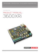
Mount the unit using the two centre xing slots, and allow satisfactory cooling air to ow
over the ns (vertically, with 50 mm end space). The unit must have a substantial earth
connection. Connect the earth (cross-sectional area at least 6 mm
2
) to the heatsink earth
screw provided. Use a star washer to obtain optimum earth continuity.
175 mm
165 mm
70 mm
200 mm
fin
100 mm
side view
plan view
3600XRi
airflow
heatsink earth screw
(90 mm : 36 A)
terminals
terminals
terminals
70 61
60 51
1 16
cover
A1+
A2-
L2/N
L
F2-
F1+
Figure 1 Mechanical dimensions
3600XRi
Suitable xing bolts:
4/8/16/32 A unit: M5 x 35 mm
36 A unit: M5 x 50 mm

3
Guide for systems used in the EU
3 3
Guide for systems used in the EUGuide for systems used in the EU
Special consideration must be given to installations in member states of the European Union
regarding noise suppression and immunity. According to IEC 1800-3 (EN61800-3), the drive
units are classied as complex components only for professional assemblers, with no CE
marking for EMC.
The drive manufacturer is responsible for the provision of installation guidelines.
The resulting EMC behaviour is the responsibility of the manufacturer of the system
or installation. The units are subject to the LOW VOLTAGE DIRECTIVE 73/23/EEC and
are CE marked accordingly.
Following the procedures outlined below will normally be required for the drive system
to comply with the European regulations, some systems may require different measures.
Installers must have a level of technical competence to correctly install. Although the drive
unit itself is not subject to the EMC directive, considerable development work has been
undertaken to ensure that the noise emissions and immunity are optimised.
EN618003 species two alternative operating environments. These are the Domestic
(1st environment) and Industrial (2nd environment). There are no limits specied for
conducted or radiated emissions in the industrial environment, hence it is usual for
the AC supply lter to be omitted in Industrial systems.
Denition of an industrial environment: all establishments, other than those directly
connected to a low-voltage power supply network that supplies buildings used for
domestic purposes.
*
4 4
Multiple drivesMultiple drives
The arrangement shown below is for multiple drives with one lter, showing the star point
earthing method.
The lter should be rated for the worst case total armature current load. The drive units
are designed to function normally on unltered AC supplies shared with other thyristor DC
drives. (Not AC drives).
DRIVE 1
AC SUPPLY
FILTER
UNIT
*
DRIVE 2
24V LOGIC CONTROL CLEAN EARTH
INSULATED FROM METAL WORK
ANALOGUE 0V (COM TERMINAL 5 ON DRIVES)
CLEAN EARTH INSULATED FROM METAL WORK
BACKPLATE
METAL WORK
DOORS
110V CONTROL
CUBICLE
METAL WORK
EARTH
STAR
POINT
INCOMING SAFETY EARTH
MOTOR 2
MOTOR 1
Figure 2 Star point connections for multiple drives

4
Requirements for EMC compliance
• Keep parallel runs of power and control cables at least
0.3 metres apart. Cross-overs must be at right angles.
• Keep sensitive components at least 0.3 metres from
the drive and power supply cables.
• The AC connections from the lter to the drive must be
less than 0.3 metres or, if longer, correctly screened.
• Do not run ltered and unltered AC supply cables
together.
• Control signals must be ltered or suppressed, e.g.
control relay coils and current carrying contacts. The
drive module has built-in lters on signal outputs.
• The AC supply lter must have a good earth connection
to the enclosure back plane. Take care with painted
metal to ensure good conductivity.
• The AC input lter has earth leakage currents. Earth
RCD devices may need to be set at 5% of rated current.
• The metal enclosure will be RF ground. The AC lter,
drive earth and motor cable screen should connect
directly to the metal cabinet for best performance.
• Linear control signal cables must be screened, with
the screen earthed at the drive end only. Minimise the
length of screen stripped back and connect it to an
analogue earth point.
• (1) The motor cable must be screened or armoured
with 360 degree screen terminations to earth at each
end. The cable must have an internal earth cable and
the screen must extend into the enclosure and motor
terminal box to form a Faraday cage without gaps.
• (2) The internal earth cable must be earthed at each
end. The incoming earth must be effective at RF.
WARNING! The earth safety must always take
precedence.
5 5
Requirements for EMC complianceRequirements for EMC compliance
WARNING!
ELECTRIC SHOCK HAZARD
AC supply lters
must not be used
on supplies that
are unbalanced or
oat with respect to
earth.
The drive and AC
lter must only
be used with a
permanent earth
connection. No
plugs/sockets are
allowed in the AC
supply.
The AC supply
lter contains high
voltage capacitors
and should not
be touched for a
period of at least 20
seconds after the
removal of the AC
supply.
DRIVE
CONTROL
TERMINALS
DRIVE
AC SUPPLY
INPUTS
DRIVE
EARTH
TERMINAL
ARMATURE
AND FIELD
OUTPUTS
CONTROL
SIGNAL
FILTERS
AC SUPPLY
FILTER
UNIT
*
dc drive module
User’s metal enclosure
1
2
Figure 3 Connections for EMC compliance

5
Installation
6 6
InstallationInstallation
WARNING!
ELECTRIC SHOCK HAZARD
Disconnect the mains supply
before working on the unit. DO
NOT TOUCH PRESETS, SWITCHES
AND JUMPERS! Always use the
correct insulated adjustment
tools.
6.1
Motor installation
• Foot-mounted motors must be level and
secure.
• Ensure accurate alignment of the motor
shaft and couplings.
• Do not hammer pulleys or couplings
onto the motor shaft.
• Protect the motor from ingress of
foreign matter during installation.
Earthing: Connect the motor to the system
enclosure earth.
6.2
Drive installation
Requirements during installation and
operation:
• Avoid vibration.
• Protect the drive from pollutants.
• Ambient operating temperature must be
within -10ºC and +40ºC. To comply with
UL requirements, the temperature of the
surrounding air must not exceed 50ºC.
POWER CABLING: Use correctly rated
cable: minimum 600 Vac, 2 x armature
current, enclosed in metal conduit or
trunking, or screened. The screen must be
earthed at the motor and drive - refer to "5
Requirements for EMC compliance" on page
4.
FUSING: The drives MUST BE FUSED
EXTERNALLY with semiconductor fuses. The
fuses must be semiconductor types with
a maximum amps squared seconds rating
according to the Rating table, page 28).
The fuse current rating must be at least
1. 75 times the armature current. The
voltage rating must be suitable for the
AC supply. Failure to use the correct
semiconductor fuse ratings will invalidate
any warranty. Special consideration must
be given to installations in member states
of the EU. Refer to "5 Requirements for EMC
compliance" on page 4.
CONTROL SIGNALS: Avoid running signal
cables close to power cables. Earth the
screens at the drive end only.
SUPPRESSION: The drives have excellent
noise immunity. However, installations
involving electrical welding or RF induction
heating may require further lters on the
line and armature terminals. Contactor coils
and sparking contacts may also require
suppression. A 100 Ω resistor in series with
a 0.1 µF capacitor is usually adequate in
these situations.
MECHANICAL: Optimise heatsink airow.
Avoid vibration and ambient temperature
outside -10 to +45°C. Protect the drive from
pollutants.
MOTOR: Ensure the motor is correctly
wired and that the motor and load are
free and safe to rotate. The motor must
ideally have a minimum armature time
constant of approximately 10 ms (T = L/R).
For motors with lower time constants e.g.
servo-motors, use an armature choke in
series with the motor (refer to the motor
supplier for choke data). Failure to do this
may cause damage.

6
Installation
6.3
Typical applications
Figure 4 Basic connection
SPRINT ELECTRIC LTD. does not
accept any liability whatsoever for
the installation, tness for purpose or
application of its products. It is the users
responsibility to ensure that the unit is
correctly used and installed.
Health and Safety at Work
Devices constitute a safety hazard. It is
the responsibility of the user to ensure
compliance with any Acts or By-Laws
in force. ONLY skilled persons should
install this equipment.
1
+10
2
MIN
3
I/P
4
MAX
5
COM
6
AUX
7
RUN
8
COM
9
TAC
10 11 12
F2-
F1+
STA
JOG
FWD
REV
A1+ A2- L2/N L
13
14 15 16
RAMP
quench
RL2
RL2 shown
energised
SP64 XIP
+
RL2
COIL
RL2
SET
RESET
MAX O/P
+10
-10
terminal 4
68
67
IP
66
-IP
65
XIP
64
-12
63
SS
62
+12
61
TIM
60
REV
59
COM
58
DO
57
SO
56
RO
55
IO
54
ZS
53
ST
52
-24
51
70
69
COM +24
IP IO
DC TACHO
(optional)
COM must be earthed for protective class 1
FIELD
AC I/P
DANGER
ELECTRIC SHOCK RISK
MOTOR
RUN
10K
BASIC CONNECTION. FORWARD AND REVERSE SPEED CONTROL BY POTENTIOMETER
ccw
cw
OPTIONAL
START
*
(ramp
to stop)
1
+10
2
MIN
3
I/P
4
MAX
5
COM
6
AUX
7
RUN
8
COM
9
TAC
10 11 12
F2-
F1+
STA
JOG
FWD
REV
A1+ A2- L2/N L
13
14 15 16
RAMP
quench
RL2
RL2 shown
energised
SP64 XIP
+
RL2
COIL
RL2
SET
RESET
MAX O/P
+10
-10
terminal 4
68
67
IP
66
-IP
65
XIP
64
-12
63
SS
62
+12
61
TIM
60
REV
59
COM
58
DO
57
SO
56
RO
55
IO
54
ZS
53
ST
52
-24
51
70
69
COM +24
IP IO
DC TACHO
(optional)
COM must be earthed for protective class 1
RUN
ALTERNATIVE FORWARD AND REVERSE SPEED CONTROL BY CENTRE ZERO POTENTIOMETER
ccw
cw
10K
centre zero
SPEED
SPEED
If OPTIONAL START (ramp to stop) is not required,
connect START T13 directly to COM
*
We recommend two fuses
for line-to-line operation, only
one fuse is necessary on the live
(L) for line-to-neutral operation
incoming
FUSES
OPTIONAL
START
*
(ramp
to stop)
If OPTIONAL START (ramp to stop) is not required,
connect START T13 directly to COM
*
FIELD
AC I/P
DANGER
ELECTRIC SHOCK RISK
MOTOR
We recommend two fuses
for line-to-line operation, only
one fuse is necessary on the live
(L) for line-to-neutral operation
incoming
FUSES
We recommend an initial start using the Basic Connection.
WARNING!
PERSONAL INJURY AND/OR
EQUIPMENT DAMAGE HAZARD
To ensure safe operation of the unit, always apply the ac supply before closing the
run contact to prevent spurious ring due to erratic mains contactor operation.
Do not remove the ac supply while the armature current is owing - quench the
drive rst using the run contact.
1
+10
2
MIN
3
I/P
4
MAX
5
COM
6
AUX
7
RUN
8
COM
9
TAC
10 11 12
F2-
F1+
STA
JOG
FWD
REV
A1+ A2- L2/N L
13
14 15 16
RAMP
quench
RL2
RL2 shown
energised
SP64 XIP
+
RL2
COIL
RL2
SET
RESET
MAX O/P
+10
-10
terminal 4
68
67
IP
66
-IP
65
XIP
64
-12
63
SS
62
+12
61
TIM
60
REV
59
COM
58
DO
57
SO
56
RO
55
IO
54
ZS
53
ST
52
-24
51
70
69
COM +24
IP IO
DC TACHO
(optional)
COM must be earthed for protective class 1
FIELD
AC I/P
DANGER
ELECTRIC SHOCK RISK
MOTOR
RUN
10K
BASIC CONNECTION. FORWARD AND REVERSE SPEED CONTROL BY POTENTIOMETER
ccw
cw
OPTIONAL
START
*
(ramp
to stop)
1
+10
2
MIN
3
I/P
4
MAX
5
COM
6
AUX
7
RUN
8
COM
9
TAC
10 11 12
F2-
F1+
STA
JOG
FWD
REV
A1+ A2- L2/N L
13
14 15 16
RAMP
quench
RL2
RL2 shown
energised
SP64 XIP
+
RL2
COIL
RL2
SET
RESET
MAX O/P
+10
-10
terminal 4
68
67
IP
66
-IP
65
XIP
64
-12
63
SS
62
+12
61
TIM
60
REV
59
COM
58
DO
57
SO
56
RO
55
IO
54
ZS
53
ST
52
-24
51
70
69
COM +24
IP IO
DC TACHO
(optional)
COM must be earthed for protective class 1
RUN
ALTERNATIVE FORWARD AND REVERSE SPEED CONTROL BY CENTRE ZERO POTENTIOMETER
ccw
cw
10K
centre zero
SPEED
SPEED
If OPTIONAL START (ramp to stop) is not required,
connect START T13 directly to COM
*
We recommend two fuses
for line-to-line operation, only
one fuse is necessary on the live
(L) for line-to-neutral operation
incoming
FUSES
OPTIONAL
START
*
(ramp
to stop)
If OPTIONAL START (ramp to stop) is not required,
connect START T13 directly to COM
*
FIELD
AC I/P
DANGER
ELECTRIC SHOCK RISK
MOTOR
We recommend two fuses
for line-to-line operation, only
one fuse is necessary on the live
(L) for line-to-neutral operation
incoming
FUSES

7
Commissioning
7 7
CommissioningCommissioning
7.1
Initial settings - without power
The suggested Comissioning strategy is to start in the safest possible mode of operation and
progressively exercise each element of the system until full functionality has been achieved.
For this reason, all drive units are shipped to run using the:
1. Set the following switches:
• Select the current range using switches S1 and S2 - set to
the minimum motor rating that includes the motor rating
current. Refer to "Figure 6 User adjustments" on page 10.
• Set switches S3 and S4 to OFF to select feedback full scale at
100%, 50 V.
• Set switches S5, S6 and S7 to provide the desired relay
function -
Refer to "Figure 6 User adjustments" on page 10.
•
Set switch S8 to ON to select Armature Voltage, and the Tach
from T9 must be disconnected.
MAX SPEED
Fully anti-clockwise
MIN SPEED
Fully anti-clockwise
FORWARD UP RAMP
Fully anti-clockwise
FORWARD DOWN RAMP
Fully anti-clockwise
REVERSE UP RAMP
Fully anti-clockwise
REVERSE DOWN RAMP
Fully anti-clockwise
STABILITY
Mid-way
IR COMP
Fully anti-clockwise
MAX CURRENT
Set the MAX CURRENT from your motor rating
plate - clockwise rotation of the potentiometer
gives 0-100% current limit. For example, 50%
rotation provides a 50% current limit for the
selected current range set by switches S1 and S2.
3. Links - ensure that:
a. The link for the MAX CURRENT potentiometer mode is in the POS I/
NEG I position.
b. The 4Q TORQUE/2Q TORQUE/SPEED link is in the SPEED position.
c. 1S and ZS QUENCH links are tted.
• highest supply voltage option at nominal speed • ARMATURE VOLTAGE feedback mode
• lowest speed range • lowest current range
To avoid damage, ensure the supply selection jumper on the drive matches the
incoming ac supply - refer to "Figure 6 User adjustments" on page 10.
2. For an initial start, adjust the following presets:

8
Commissioning
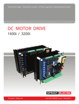
7.2
Block diagram
1
15
16
4
70
66
65
2
3
64
13
14
+10 REF
FWD
REV
MAX
IP
+IP
-IP
I/P
FORWARD
REVERSE
LOGIC
FWD
REV
MIN
XIP
START
JOG
5
COM
7
RUN
8
COM
9
TACH
52
ST
53
ZS
A+
59
REV
11
NO
10
NC
12
CO
56
SO
54
IO
60
TIM
69
IOM
55
RO
57
DO
A-
L2/N
L1/L
F+
F-
+10 V REF
+
-
+
+
+
+
+
+
-
+
Upper
4-20 mA
links
390R
x 2.5
UP
DOWN
RAMP
+10 V REF
-10 V REF
+10 V REF
6
AUX
SPEED
-
+
50K
100K
FORWARD
UP
DOWN
P3
P4
P8
P11
REVERSE
Lower
P2
5K
-1
50K
+24 V
FS
1S
ZS
1 s delay
zero setpoint
detect
direction
detect
zero speed
detect
P1
MAX
SPEED
P5
IR COMP
switched
inverter
I
a
> 110%
50%
STALL
Speed PI
Current
Limit
-
+
STABILITY
P7
IMAX+
P6
IMAX
P10
Current PI
Synch &
Firing
Bridge select
& zero current
detection
-1
2Q
x 0.5
4Q
FWD
REV
V
a
/50
S4
x4
S3
x2
x1
S8
current
scale
S1
S2
F2
F1
110 V
240 V
+24 V
+12 V
+10 V
STALLED
S6
S5
S7
ZERO
STALL
REVERSE
TACH/AVF
-24 V
STALL
TIMER
RUNNING
x1
Motor
Armature
Mains
Supply
Power
Supply
Motor
Field
Lower control terminal
Upper control terminal
Power terminal
Switch
Link
Preset
KEY
*
*
*
* NOTE: Fit only one link to SPEED, 2Q and 4Q
(marked below with *) at any time.
Refer to "7.4.3.3 Torque/Speed Mode" on page 16.

9
Commissioning
1
15
16
4
70
66
65
2
3
64
13
14
+10 REF
FWD
REV
MAX
IP
+IP
-IP
I/P
FORWARD
REVERSE
LOGIC
FWD
REV
MIN
XIP
START
JOG
5
COM
7
RUN
8
COM
9
TACH
52
ST
53
ZS
A+
59
REV
11
NO
10
NC
12
CO
56
SO
54
IO
60
TIM
69
IOM
55
RO
57
DO
A-
L2/N
L1/L
F+
F-
+10 V REF
+
-
+
+
+
+
+
+
-
+
Upper
4-20 mA
links
390R
x 2.5
UP
DOWN
RAMP
+10 V REF
-10 V REF
+10 V REF
6
AUX
SPEED
-
+
50K
100K
FORWARD
UP
DOWN
P3
P4
P8
P11
REVERSE
Lower
P2
5K
-1
50K
+24 V
FS
1S
ZS
1 s delay
zero setpoint
detect
direction
detect
zero speed
detect
P1
MAX
SPEED
P5
IR COMP
switched
inverter
I
a
> 110%
50%
STALL
Speed PI
Current
Limit
-
+
STABILITY
P7
IMAX+
P6
IMAX
P10
Current PI
Synch &
Firing
Bridge select
& zero current
detection
-1
2Q
x 0.5
4Q
FWD
REV
V
a
/50
S4
x4
S3
x2
x1
S8
current
scale
S1
S2
F2
F1
110 V
240 V
+24 V
+12 V
+10 V
STALLED
S6
S5
S7
ZERO
STALL
REVERSE
TACH/AVF
-24 V
STALL
TIMER
RUNNING
x1
Motor
Armature
Mains
Supply
Power
Supply
Motor
Field
Lower control terminal
Upper control terminal
Power terminal
Switch
Link
Preset
KEY
*
*
*
Figure 5 Block diagram

10
Commissioning
Figure 6 User adjustments
WARNING!
When power is applied to the drive,
ALWAYS use an insulated tool when adjusting the presets.
Rotate clockwise to increase
current. S1 and S2 select the
range. Set the PRESET function
using the MODE jumper.
POS I
NEG I
MOTOR fwd/rev BRAKE fwd/rev
FWD + and -
REV + and -
Rotate clockwise to increase
response. Excessive rotation
may cause instability.
Rotate clockwise to increase
level of armature voltage droop
compensation. Excessive
rotation may cause instability.
Rotate clockwise to increase
drive acceleration in forward
direction from (+) 1 to 30 s.
Rotate clockwise to increase
minimum speed. Use to adjust
4-20 mA loop burden resistor
between 0 and 390 Ω if 4-20 mA
mode is selected.
Rotate clockwise to increase
speed. Change the range with
S3 and S4.
MIN SPEED set to give 250 Ω between T2 and T6.
4-20 mA: link both and terminal 2 is input, 5 is return.
Link for
50% STALL
THRESHOLD.
CURRENT
STALL
TAC/AVF
DRIVE STALL S5 ON
ZERO SPEED S6 ON
0-25%
0-50% 0-75%
0-100%
25-50V
50-100V
100-200V
200-400V
OFF ON
1 2 3 4 5 6 7 8
ZERO
REVERSE
RANGE
SPEED
RANGE
S1
S2
CURRENT
RANGE
Select between four maximum current ranges.
100% represents the maximum unit rating.
Use the MAX CURRENT PRESET to adjust from 0% to
the selected maximum percentage.
S3
S4
SPEED
RANGE
Select between four maximum feedback voltage ranges.
Use the MAX SPEED PRESET to adjust within the
range. The drive will control from 0 V to the selected
maximum 0-10 V input.
S5
S6
S7
STALL
ZERO
REVERSE
S5, 6 and 7 select the function of the relay on terminals
10, 11 and 12. The relay driver outputs also appear on
T52 (stall), T53 (zero), T59 (reverse) and T60 (timer). If
more than one function is selected, the functions are
ANDED - refer to page 7.
S5 - when ON, the relay remains energised until a stall
condition occurs.
S6 - when ON, the relay remains eneergised until the
speed falls below 1%.
S7 - when ON, the relay is energised for speeds above
5% of full scale in the forward direction, and
de-energises at zero or reverse speed.
S8
TAC/AVF
Select the speed feedback source:
When ON, ARMATURE VOLTAGE is selected (default).
When OFF, TACHO is selected.
4Q TORQUE
2Q TORQUE
SPEED
0 to +10 V for 0 to 100% +ve current limit.
0 to +/-10 V for 0 to +/-100%.
DANGER!
ELECTRIC SHOCK HAZARD
SUPPLY
SELECT
*
ANTI-CLOCKWISE MID-WAY
CLOCKWISE
Stall lamp lights and drive quenches if the stall timer
trips - the time depends on the current demand:
STANDARD WITH 50% THRESHOLD
150% 30 secs 150% 5 secs
125% 60 secs 100% 30 secs
115% 120 secs 75% 60 secs
100% no trip 50% no trip
MAX
SPEED
MIN
SPEED
UP RAMP
DOWN RAMP
STAB
IR
COMP
MAX CURRENT
UP RAMP
DOWN RAMP
F
O
R
W
A
R
D
REVERSE
POS I
MOTOR
FWD
NEG I
BRAKE
REV
Rotate clockwise to increase
drive deceleration in forward
direction from (+) 1 to 30 s.
Rotate clockwise to increase
drive acceleration in reverse
direction from (-) 1 to 30 s.
Rotate clockwise to increase
drive deceleration in reverse
direction from (-) 1 to 30 s.
0 to +5 V for 0 to 100% +ve and -ve current limit.
F2-
F1+
A1+
A2-
L2/N
L
1
+10
2
MIN
3 4
MAX
5
COM
6
AUX
7
RUN
8
COM
9
TACH
10 11 12 13 14 15 16
START
JOG
FWD
REV
1
0
K
N
O
10 11
12
50%
STALL
LINK
FOR
4-20 mA
FS
1S
ZS
QUENCH
+
-
TIMER
STALL
*
SELECTOR
TERMINALS
This jumper selects the appropriate supply
tap on the control transformer.
Refer to the specification for tolerances.
Check the model type.
HIGH LOW
HIGH
415
240
60
LOW
240
110
30
When ON, stall timer tripped.
When ON, positive current demand.
When ON, negative current demand.
When ON, stall timer ticking and tripped.
TIMER
1 s ON
50 ms OFF
OR
GATE
OR
GATE
FS
1S
ZS
RUN
ZERO
SPEED
Quench
pulses
when ON
QUENCH controls the removal of the firing pulses.
MODE
See the label on the side of the transformer for the model type.

11
Commissioning
1
+10 +10 V precision reference. 10 mA maximum. Short-circuit proof.
2 MIN
Minimum (ACW) end of setpoint potentiometer, or 4-20 / 0-20 mA current loop input.
3
I/P +/-10 V input for speed setpoint.
4
MAX
Maximum (CW) end of setpoint pot in bi-directional systems. Set by FWD/REV inputs to +10 V or -10 V
(defaults to -10 V if T15 and T16 are unused).
5
COM COMMON (4-20 mA / 0–20 mA return). Internally connected to T8, T58 and T68.
6
AUX Auxiliary input. Function set by links – refer to "7.4.3.3 Torque/Speed Mode" on page 16.
7
RUN
Connect to COMMON to run. Function set by links – refer to "7.4.3.5 Quench Mode" on page 17. It
is good practice to connect a normally open auxiliary contact of the drive’s supply contactor in series
with this input.
(WARNING: Run is an electronic inhibit function. The eld remains
energised and all power terminals remain "live". RUN must not be relied
upon during hazardous operations).
8
COM Common - internally connected to T5, T58 and T68.
9
TACH Tacho input 25-400 V - negative for forward rotation with positive setpoint.
10
N/C
Relay contact rating 1 A, 125 Vac. Congurable function – refer to "7.4.2.3 S5 / S6 / S7" on page 15.
11
N/O
12
C/O
8
COM N/C STOP pushbutton.
13
N/O START pushbutton.
14
START latch line (JOG).
15
N/C FORWARD pushbutton.
16
N/C REVERSE pushbutton.
STOP
START
COM
8
13
14
15
16
7.3
Terminal descriptions
7.3.1
Control terminals

12
Commissioning
51
-24 -24 V relay supply. 25 mA.
NOT SHORT-CIRCUIT PROOF
52
ST
Stall relay driver output. Maximum 25 mA. External relay is de-energised when stall timer trips if
connected as in "Figure 7 Relay circuits" on page 13.
53
ZS
Zero speed relay driver output. Maximum 25 mA. External relay is de-energised at zero speed if
connected as in "Figure 7 Relay circuits" on page 13.
54
IO Scaled current output. ±5 V for ±100%. 1 kΩ output impedance.
55
RO Speed setpoint ramp output. ±10 V for ±100%. 1 kΩ output impedance.
56
SO
Speed output. Full-scale reading determined by max speed preset setting. Variable between ±4 V for
±100% to ±9 V for ±100%. 1 kΩ output impedance. Typically 7.5 V full-scale.
57
DO Inverted total speed demand output. +10 V for -100%; -10 V for +100%. 1 kΩ output impedance.
58
COM COMMON. Internally connected to T5, T8 and T68.
59
REV
Relay driver. Maximum 25 mA. External relay is de-energised when the speed reverses or at zero
speed if connected as in "Figure 7 Relay circuits" on page 13.
60
TIM
Relay driver. Maximum 25 mA. External relay is de-energised when the stall timer is operating
(current demand > 105%) if connected as in "Figure 7 Relay circuits" on page 13.
61
+12 +12 V output. 10 mA maximum.
62
SS Stop/Start input. Close to -12 V to force a stall condition. Close to +12 V to release stall condition.
63
-12 -12 V output. 10 mA maximum.
64
XIP
Input to speed setpoint ramp circuit when START relay RL2 is de-energised (T3 is disconnected).
±10 V for ±100%.
65
-IP Auxiliary inverting speed input. 0V to -10 V for 0V to +100% speed; 0V to +10 V for 0 to -100% speed.
66
+IP Auxiliary non-inverting speed input. ±10 V for ±100%.
67
+24 +24 V output. 25 mA maximum.
NOT SHORT-CIRCUIT PROOF
68
COM Drive Common. Internally connected to T5, T8 and T58.
69
IOM Metering output, 0 to 5 Vdc representing 0 to 100% scaled armature current. See SW1 and SW2.
70
IP
Auxiliary input to speed demand scaled ±10 V for ±100%.
Do not use if TORQUE/SPEED link is in the SPEED position as the auxiliary input function is
already being used by the AUX (T6) auxiliary terminal.
7.3.2
Ancillary terminals

13
Commissioning
7.3.3
Power terminals
A1+ Motor armature connection (positive).
A2- Motor armature connection (negative).
L2/N Line ac return; either neutral or L2.
L Line ac supply input.
F2- Motor eld connection (negative).
F1+ Motor eld connection (positive).
Terminals
52, 53, 59, 60
Minimum coil
resistance 2k8 Ω
RL
Terminal 51 (-24 V)
Figure 7 Relay circuits

14
Commissioning
7.4
Preset, switches and links
7.4.1
Presets
Preset Description
MAX SPEED Sets maximum speed for 100% demand.
MIN SPEED
Sets minimum speed for application.
Note: Minimum speed function only
operates if the speed demand is
from a 10k potentiometer connected
between terminals 1 and 2 with its wiper
connected to terminal 3.
When operating with a 4 – 20 mA or 0 -
20 mA reference, the MIN SPEED preset
is used to adjust the burden resistance.
FORWARD UP RAMP Forward acceleration.
FORWARD DOWN RAMP Forward acceleration.
REVERSE UP RAMP Reverse acceleration.
REVERSE DOWN RAMP Reverse acceleration.
STAB Stability.
IR
COMP
IR compensation.
MAX CURRENT
2x current limit presets. Refer to "8.2
Maximum Current Mode" on page 21.
7.4.2
Switches
7.4.2.1
S1 / S2
These two switches set the maximum current as a
percentage of the rated current of the unit. The MAX
CURRENT presets can then adjust the maximum current
between this current to zero.
S1 S2 % of rated
OFF OFF 25%
ON OFF 50%
OFF ON 75%
ON ON 100%
/