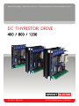
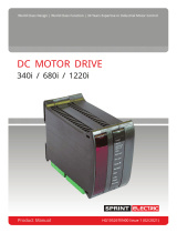
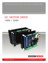
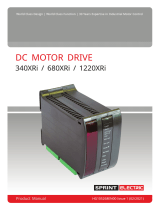
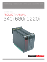
Sprint Electric 400 800 1200 drives offer precise motor speed control for industrial applications. With closed-loop control of armature current and feedback voltage, these drives ensure accurate torque and speed control of DC motors. Features include stall protection, short-term high torque capability, independent current/speed loop control, and various input/output options. Ideal for applications like conveyors, pumps, and fans, Sprint Electric drives provide reliable and efficient motor control solutions.
Sprint Electric 400 800 1200 drives offer precise motor speed control for industrial applications. With closed-loop control of armature current and feedback voltage, these drives ensure accurate torque and speed control of DC motors. Features include stall protection, short-term high torque capability, independent current/speed loop control, and various input/output options. Ideal for applications like conveyors, pumps, and fans, Sprint Electric drives provide reliable and efficient motor control solutions.


-
 1
1
-
 2
2
-
 3
3
-
 4
4
-
 5
5
-
 6
6
-
 7
7
-
 8
8
-
 9
9
-
 10
10
-
 11
11
-
 12
12
-
 13
13
-
 14
14
-
 15
15
-
 16
16
-
 17
17
-
 18
18
-
 19
19
-
 20
20


Sprint Electric 400 800 1200 drives offer precise motor speed control for industrial applications. With closed-loop control of armature current and feedback voltage, these drives ensure accurate torque and speed control of DC motors. Features include stall protection, short-term high torque capability, independent current/speed loop control, and various input/output options. Ideal for applications like conveyors, pumps, and fans, Sprint Electric drives provide reliable and efficient motor control solutions.
Ask a question and I''ll find the answer in the document
Finding information in a document is now easier with AI
Related papers
-
 Sprint Electric 340i 680i 1220i User manual
-
 Sprint Electric 1600i 3200i User manual
-
 Sprint Electric 340XRi 680XRi 1220XRi User manual
-
 Sprint Electric 340i 680i 1220i User manual
-
 Sprint Electric 340XRi 680XRi 1220XRi User manual
-
 Sprint Electric 3600XRi User manual
-
 Sprint Electric 3600XRi User manual
-
 Sprint Electric 3600XRi User manual
-
 Sprint Electric 340 680 1220 User manual
-
 Sprint Electric 340 680 1220 User manual


Other documents
-
Eurotherm ER-340i/ER-680i/ER1220 Owner's manual
-
Eurotherm ER-340XRi/ER-680XRi/ER-1220XRi DC Drive Owner's manual
-
-
-
-
ABB DCS 600 MultiDrive Series User manual
-
Control Techniques Mentor II User manual
-
ABB DCS 400 User manual
-
Baldor Universal Remote mn792 User manual
-
Siemens Microscope & Magnifier A1 User manual