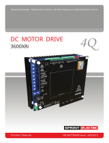
Page is loading ...

World Class Design | World Class Function | 30 Years Expertise In Industrial Motor Control
PRODUCT MANUAL:
HG105003 ISS1
3600XRi

3600XRi Product Manual
HG105008 Issue 1 3
Contents
1 Important safety notes ....................................................................... 4
2 Models ................................................................................................. 5
3 Description .......................................................................................... 6
4 Block diagram .................................................................................... 7
4.1 Terminal descriptions ......................................................................................... 8
5 Installation ......................................................................................... 10
5.1 Electrical ............................................................................................................ 11
5.2 Motor .................................................................................................................. 11
6 Presets, switches and links............................................................... 12
6.1 Presets ................................................................................................................ 12
6.2 Switches ............................................................................................................. 12
6.3 Links ..................................................................................................................... 14
7 Commissioning ................................................................................. 20
7.1 Initial settings ..................................................................................................... 20
8 Technical specifications .................................................................. 23
9 Typical applications ......................................................................... 26
9.1 Basic connection ............................................................................................. 26
9.2 Start, stop, forward and reverse .................................................................... 26
10 Troubleshooting ................................................................................ 27
11 Notes .................................................................................................. 29
Sprint Electric Ltd accepts no liability whatsoever for the installation, fitness for purpose
or application of its products. It is the user’s responsibility to ensure the unit is correctly
rated, used and installed.
The contents of this manual are accurate at the time of printing. However, the
manufacturers reserve the right to change the content and product specification
without notice. No liability is accepted for errors or omissions.

3600XRi Product Manual
4 HG105008 Issue 1
1 Important safety notes
Drives and process control systems are a very important part of creating
better quality and value in products, but they must be designed, installed
and used with great care to ensure everyone’s safety. Pay particular
attention to all the safety warnings in this section.
Electric shock risk! Electrical devices constitute a safety hazard. It is
the responsibility of the user to ensure compliance with any acts or
bylaws in force.
All personnel who will install, use or maintain this equipment must
read and understand this manual before applying power to the
device. If in doubt, refer to the supplier.
Only install this device if you have the skills and knowledge to use it
safely.
Only use qualified personnel to design, construct, operate and
maintain your systems.
Make sure that all personnel who use or maintain the equipment are
aware of all the hazards that are involved in your equipment and
processes.
If you have any doubts about the safety of your system or process,
do not proceed without first consulting an expert.
The ac supply filters must not be used on unbalanced power
supplies, or those that float with respect to earth.
The drive and ac filter (if supplied) must only be used with a
permanent earth connection. Do not use plugs and sockets in the ac
supply.
The ac supply filter (if supplied) contains high-voltage capacitors and
should not be touched for 20 seconds after the removal of the ac
supply.
This controller is an open-chassis component for use in a suitable enclosure.

3600XRi Product Manual
HG105008 Issue 1 5
2 Models
Sprint Electric offers a range of isolated dc thyristor 4-quadrant drives. In the
3600XRi model range each drive has the same features and terminals. Select
the appropriate model depending on the motor current and the available
supply voltage.
3600XRi
drive type
ac supply
voltage
(Vac)
Nominal output
(Vdc)
100% amps
dc output
(Adc)
4/LN
240/110
180/90
4
8/LN
240/110
180/90
8
16/LN
240/110
180/90
16
16/LL
415/240
320/180
16
32/LL
415/240
320/180
32
36/LL
415/240
320/180
36
Note: 1. Low volt versions are available, operating on 60/30 Vac supplies
giving 48/24 Vdc output and 48/24 Vac supplies giving 38/18 Vdc
output.
2. Top terminals can be added on request.
3. All types are of open-chassis construction with rear heatsink.
4. Nominal output is based on a maximum Form Factor (ratio of RMS
ac supply current to dc output) of 1.5.

3600XRi Product Manual
6 HG105008 Issue 1
3 Description
The 3600XRi models use closed-loop control of both armature current and
voltage to give precise control of the motor torque and speed. The motor
and drive are thermally protected by a stall timer that automatically
removes power after approximately 30 seconds if the required speed cannot
be achieved.
The drives will provide up to 150% of the preset maximum current during this
period, allowing high short-term torques during acceleration or shock
loading.
Independent control of either the current or speed loops by external inputs
allows torque or speed control applications with overspeed or overcurrent
protection. The speed demand signal may be derived from a potentiometer,
0-10 V signal, 0 -20 mA or 4-20 mA loop. The current limit can be derived
from a potentiometer or 0 – 10 V signal. A bipolar speed demand is only
possible with a voltage input.
The speed feedback signal may be selected to be the armature voltage or
a shaft mounted tacho.
The drives are chassis components and must be mounted in a suitable
enclosure with a fused supply.
The fuses must be semiconductor types according to the recommendation
given in the Protection section of the Technical specifications on page 23.
Failure to use the correct semiconductor fuse ratings will invalidate
any warranty.
Control of shaft direction can be by linear voltage signals or pushbuttons.
Direct connection to PLC logic controllers is also possible.
Braking of the motor can be fast or ramped, and facilities exist which allow
choice of action dependent on direction of rotation. Braking energy is
returned to the supply.
Speed and current range are selected by on board function switches and
independent adjustment presets are provided for:
Forward up ramp
Forward down ramp
Reverse up ramp
Reverse down ramp.
The positive and negative current limits are also independently adjustable.
Motoring and braking torque can be adjusted independent of the direction
of rotation.
There are a number of additional inputs and outputs which are all electrically
isolated from the mains supply to allow simple interfacing to external sources.

3600XRi Product Manual
8 HG105008 Issue 1
4.1 Terminal descriptions
4.1.1 Control terminals
Term.
Description
1 +10
+10 V precision reference. 10 mA maximum. Short-circuit proof.
2 MIN
Minimum (ACW) end of setpoint potentiometer, or 4 - 20 mA / 0 –
20 mA current loop input.
3 I/P
± 10 V input for speed setpoint.
4 MAX
Maximum (CW) end of setpoint potentiometer in bi-directional
systems. Set by FWD/REV inputs to +10V or -10V (defaults to -10 V
if T15 and T16 are unused)
5 COM
COMMON (4 - 20 mA / 0 – 20 mA return). Internally connected
to T8, T58 and T68.
6 AUX
Auxiliary input. Function set by links – see section 6.3.
7 RUN
Connect to COMMON to run. Function set by links – see section
6.3. It is good practice to connect a normally open auxiliary
contact of the drive’s supply contactor in series with this input.
RUN is an electronic inhibit function. The field remains
energised and all power terminals remain live. Do not
rely on RUN to make the system safe during hazardous
operations on the machine or control system.
8 COM
COMMON. Internally connected to T5, T58 and T68.
9 TACH
Tacho input 25 – 400 V. Negative for forward rotation.
10 N/C
Relay contact rating 1 A, 125 Vac. Configurable function – see
section 7.1.2.
11 N/O
12 C/O
8 COM
N/C STOP pushbutton
8
13
N/O START pushbutton
13
14
START latch line
14
15
N/C FORWARD pushbutton
15
16
N/C REVERSE pushbutton
16

3600XRi Product Manual
HG105008 Issue 1 9
4.1.2 Ancillary terminals
51 -24
-24 V relay supply. 25 mA. NOT SHORT-CIRCUIT PROOF.
52 ST
Stall relay driver output. Maximum 25 mA. External relay is de-
energised when stall timer trips if connected as in Figure 4-2.
53 ZS
Zero speed relay driver output. Maximum 25 mA. External relay is
de-energised at zero speed if connected as in Figure 4-2
54 IO
Scaled current output. ±5 V for ±100%. 1 kΩ output impedance.
55 RO
Speed setpoint ramp output. ±10 V for ±100%. 1 kΩ output
impedance.
56 SO
Speed output. Full-scale reading determined by max speed
preset setting. Variable between ±4 V for ±100% to ±9 V for
±100%. 1 kΩ output impedance.
57 DO
Inverted total speed demand output. +10 V for -100%; -10 V for
+100%. 1 kΩ output impedance.
58 COM
COMMON. Internally connected to T5, T8 and T68.
59 REV
Relay driver. Maximum 25 mA. External relay is de-energised
when the speed reverses or at zero speed if connected as in
Figure 4-2.
60 TIM
Relay driver. Maximum 25 mA. External relay is de-energised
when the stall timer is operating (current demand > 105%) if
connected as in Figure 4-2.
61 +12
+12 V output. 10 mA maximum.
62 SS
Stop/Start input. Close to -12 V to force a stall condition. Close to
+12 V to release stall condition.
63 -12
-12 V output. 10 mA maximum.
64 XIP
Input to speed setpoint ramp circuit when relay RL2 is de-
energised (T3 is disconnected). ±10 V for ±100%.
65 –IP
Auxiliary inverting speed input.
0V to -10 V for 0V to +100% speed;
0V to +10 V for 0 to -100% speed.
66 +IP
Auxiliary non-inverting speed input. ±10 V for ±100%.
67 +24
+24 V output. 25 mA maximum. NOT SHORT-CIRCUIT PROOF.
68 COM
Drive Common. Internally connected to T5, T8 and T58.

3600XRi Product Manual
10 HG105008 Issue 1
69 IOM
Metering output, 0 to 5 Vdc representing 0 to 100% scaled
armature current. See SW1 and SW2. Internally connected to T6.
70 IP
Auxiliary input to speed demand scaled ±10 V for ±100% (if the
Torque/Speed link is in the SPEED position).
Figure 4-2: Relay circuits
4.1.3 Power terminals
A1 +
Motor armature connection (positive).
A2 -
Motor armature connection (negative).
L2/N
Line ac return; either neutral or L2.
L
Line ac supply input.
F2-
Motor field connection (negative).
F1+
Motor field connection (positive).
5 Installation
Make sure the ac power supply is disconnected before working on
the unit.
The unit has two centre fixing slots for mounting.
Mount the unit to allow at least 50 mm clear above and below the unit to
allow cooling air to circulate over the heatsink fins.
Make sure the heatsink is earthed with the M5 screw provided at the front
edge. The earth connection should have a cross sectional area of at least
6 mm
2
.

3600XRi Product Manual
HG105008 Issue 1 11
Figure 5-1: Mounting dimensions
5.1 Electrical
5.1.1 Power cables
Make sure the power cabling is correctly rated at 2x armature current with a
minimum voltage rating of 600 Vac.
Note: If the motor cable is screened, it must be earthed at the motor AND
the drive.
5.1.2 Fusing
Semiconductor fuses must be used in the ac supply. Failure to do so will
invalidate any warranty.
Note: Recommended fuses are detailed in the Protection section of the
Technical specifications on page 23.
5.1.3 Control signals
Do not run signal cables close to the power cables.
Earth any screens to a clean earth at the drive end only.
5.1.4 Suppression
The drives have excellent noise immunity. However, some installations, for
example those that involve electrical welding, RF induction heating,
contactor coils and sparking contacts may require further filters on the line
and armature terminals. A 100Ω resistor in series with a 0.1μF capacitor is
usually adequate.
5.2 Motor
Make sure the motor is correctly wired and that the motor and load are free
and safe to rotate.
The motor must ideally have a minimum armature time constant of
approximately 10 ms (T = L/R). For motors with lower time constants, for
example servo-motors, use an armature choke in series with the motor (refer
to the motor supplier for choke data). Failure to do this can cause damage.

3600XRi Product Manual
12 HG105008 Issue 1
6 Presets, switches and links
6.1 Presets
Preset
Description
MAX SPEED
Sets maximum speed for 100% demand
MIN SPEED
Sets minimum speed for application
Note: Minimum speed function only operates if
the speed demand is from a 10k
potentiometer connected between
terminals 1 and 2 with its wiper
connected to terminal 3.
When operating with a 4 – 20 mA or
0 - 20 mA reference, the MIN SPEED
preset is used to adjust the burden
resistance.
FORWARD UP RAMP
Forward acceleration
FORWARD DOWN RAMP
Forward deceleration
REVERSE UP RAMP
Reverse acceleration
REVERSE DOWN RAMP
Reverse deceleration
STAB
Stability
IR
comp
IR compensation
MAX CURRENT
2x current limit presets
(See section 6.3 for function)
6.2 Switches
6.2.1 S1 / S2
These two switches set the maximum current as a percentage of the rated
current of the unit. The MAX CURRENT presets can then adjust the maximum
current between this current to zero.
S1
S2
% of rated
OFF
OFF
25%
ON
OFF
50%
OFF
ON
75%
ON
ON
100%

3600XRi Product Manual
HG105008 Issue 1 13
6.2.2 S3 / S4
These two switches set the range of the speed feedback voltage.
Adjustment within the range is through the MAX Speed preset.
S3
S4
Speed Feedback Voltage
OFF
OFF
25 – 50 V
ON
OFF
50 – 100 V
OFF
ON
100 – 200 V
ON
ON
200 – 400 V
6.2.3 S5 / S6 / S7
These three switches control the function of the relay on terminals 10 - 12.
S5
S6
S7
Energised relay state
ON
OFF
OFF
Motor NOT stalled
OFF
ON
OFF
Motor speed > ±1%
OFF
OFF
OFF
Motor speed > +5% (forward)
As an example, with S6 ON and S5 and S7 OFF, when the motor speed is
greater than ±1%, the relay is energised, terminals 11 and 12 are shorted, and
terminals 10 and 12 are open. When the speed is less than ±1%, the relay is
de-energised and the opposite is true: terminals 10 and 12 are short and
terminals 11 and 12 are open.
If more than one of S5 – S7 is ON then the relay operation is the ANDing of
the switch states. For example, if switches S5 and S6 are ON, the relay is only
de-energised if the motor is stalled AND the speed is less than ±1%. In effect,
this indicates a failure for the motor to start.
6.2.4 S8
When S8 is ON, speed feedback is taken from the armature voltage. There
must be no connection to terminal T9.
When S8 is OFF speed feedback is from the TACH terminal T9.

3600XRi Product Manual
14 HG105008 Issue 1
6.3 Links
6.3.1 Supply Voltage Selector
A link is provided to configure the unit for either HIGH or LOW voltage
operation. The actual operating voltage then depends on the drive model:
HIGH
LOW
LL
415 V
240 V
LN
240 V
110 V
LV60
60 V
30 V
LV48
48 V
24 V
6.3.2 Current Limit Mode
There are three link positions which determine the function of the MAX
CURRENT presets (P6 and P10).
POS I/NEG I:
When the link is in this position, P6 sets the positive current
limit and P10 sets the negative current limit irrespective of
the direction of rotation of the motor. This is the default
position.
MOTOR/BRAKE:
With the link in this position, P6 sets the current limit when
motoring and P10 sets the current when generating
irrespective of the direction of motor rotation and the
polarity of current.
FWD/REV:
With the link in this position, P6 sets the current limit in the
forward direction and P10 sets it for the reverse direction
irrespective of the polarity of current or whether motoring
or regenerating.
6.3.3 Torque/Speed Mode
There are three positions for this link which determine the function of the AUX
analogue input on T6.
4Q TORQUE:
When the link is in this position, the voltage on T6 sets the
maximum positive and negative currents (±5V = ±100% of
calibrated current).
2Q TORQUE:
With the link in this position the voltage on T6 sets the
maximum positive current (+10V = +100% of calibrated
current). The maximum negative current is only limited
by the setting of the negative current preset.

3600XRi Product Manual
HG105008 Issue 1 15
SPEED:
With the link in this position the voltage on terminal 6 is an
auxiliary input to the speed loop demand summing
amplifier that bypasses the ramp. Positive for forward
rotation.
Section 7.1.8 describes how to operate the unit in torque control mode.
6.3.4 4/20mA and 0/20mA Modes
There are two links which can be used to configure the unit for current loop
operation with T2 the input and T5 the return.
If just the lower link is fitted 0 - 20mA operation is selected. With both links
fitted 4 - 20mA operation is possible but only if the MIN SPEED preset is
adjusted such that there is a 250Ω resistance between T2 and T5.
6.3.5 Quench Mode
There are three link positions that determine the behaviour of the quench
circuit. The factory setting is for the FS and ZS links to be fitted.
Note that opening the RUN input always resets the setpoint ramp output to
zero. The other effects of opening the RUN input depend on the position of
the links below.
FS:
With only this link fitted, the drive will be quenched
immediately by a stall condition or the removal of the
RUN signal on T7.
1S:
With only this link fitted, the drive will be quenched one
second after a stall condition or removal of the RUN
signal on T7.
ZS:
With only this link fitted, a stall condition or removal of the
RUN signal from 7 will reset the speed ramp but will not
quench the drive until one second after zero speed is
reached.
The drive will also be quenched if the motor shaft is at
“standstill”, that is, the setpoint and speed feedback are
both less than ±1%.
If no links are fitted, a stall condition or the removal of RUN from T7
will reset the speed ramp but the drive will not be quenched. Also, if
only the ZS link is fitted and the motor cannot reach zero speed,
neither a stall condition nor removal of RUN will quench the drive.
For these reasons it is recommended that either FS or 1S is fitted at all
times.
Figure 6-1 shows how the functions interact.

3600XRi Product Manual
16 HG105008 Issue 1
Figure 6-1: Drive quench circuit
Note: The AND gate (marked *) will not release the ZS function at zero speed
until the ramp circuit has an input. If the speed input is direct via T6,
the ZS link must be removed. In this case either FS or 1S MUST be fitted
if stall protection or quench via the RUN input are required.
Note: The purpose of the 1 second timer is to prevent zero speed (ZS)
quenching from being a nuisance during shaft reversals and to allow 1
second of regenerative braking to occur after the setpoint ramp has
been reset by a stall or run command.
Note: The ZS function prevents the motor shaft from “creeping” at zero
setpoint.
Note: When the RUN line operation must be rapid, but without regeneration,
use the FS (fast) link.
The effect on the motor speed for each of the link positions can be seen in
the graphs below. It is also possible to use links in more than one position.
Link
settings
Quench condition
Graph
The drive will remain
active at zero
speed.

3600XRi Product Manual
HG105008 Issue 1 17
Link
settings
Quench condition
Graph
The drive will be
quenched
immediately (by a
stall condition or
removal of RUN), ZS
function disabled.
The drive will be
quenched (by a
stall condition or
removal of RUN)
after 1 second. ZS
function disabled.
The drive quench
occurs 1 second
after the speed
reaches and
remains zero.
The drive will be
quenched
immediately (by a
stall condition or
removal of RUN) or
1 second after zero
speed is reached.
The drive will be
quenched after 1
second (by a stall
condition or
removal of RUN) or
1 second after zero
speed is reached.
Run is an electronic inhibit function. The field remains energised and
all power terminals remain live. Do not rely on RUN to make the
system safe during hazardous operations on the machine or control
system.

3600XRi Product Manual
18 HG105008 Issue 1
If the START/JOG controls on T13/T14 are used to stop the motor then the
quench behaviour is slightly different. When the STOP contact on T8 is
opened, RL2 is de-energised and the input to the ramp circuit is
disconnected from T3 and connected instead to XIP on T64. This has the
effect of ramping the speed to zero at the set rate. The graph below shows
the effect of operating the stop button with just the ZS link in place.
Note: Fitting the FS or 1S link will not affect this behaviour
Link
settings
Quench condition
Graph
The drive quench
occurs 1 second
after speed
reaches and
remains zero.
6.3.6 Stall mode
Note that stall is inhibited when 2Q or 4Q torque mode is selected, provided
the torque limit applied to T6 does not exceed 105%.
The drive regulates motor speed by adjusting the demand to the current
control loop to control motor armature current and hence torque.
If the torque required by the load exceeds that which the motor can
produce, the motor will stall.
To detect this condition, the drive has a stall detection circuit. All the time
the motor current is less than 100%, the timer in the circuit is inhibited but
when it exceeds 105% the timer ramps up at a rate proportional to the
difference between the overload current and the 105% level. For a 150%
overload the time for the stall detection circuit to operate is around 30
seconds; for a 125% overload it is around 60 seconds etc.
Should the overload fall below 105% before the stall timer has tripped, the
timer will ramp down. This characteristic of the stall circuit has the effect of
limiting the average current to the motor.
In some applications, it may be required to provide protection at a lower
average current but keep a high peak current (for example when the motor
current rating is significantly lower than the drive current rating). In this case
a feature is provided, in the form of the 50% STALL link, which reduces the
threshold at which the timer starts ramping up approximately 52.5%. A 150%
overload is still possible but the average is limited to 50% which gives a peak
to average ratio of 3:1.

3600XRi Product Manual
HG105008 Issue 1 19
If a 50% threshold is too low then a resistor can be fitted instead of the link:
Resistor/link
Threshold
Overload
Ratio
Peak %
Link
50%
150%
1:3
300%
100 kΩ
60%
150%
1:2.5
250%
220 kΩ
70%
150%
1:2.1
210%
470 kΩ
80%
150%
1:1.87
187%
1 MΩ
90%
150%
1:1.66
166%
Open
100%
150%
1:1.5
150%
6.3.7 LEDs
There are four LEDs in the top left hand corner of the drive board.
The LEDs labelled ‘+’ and ‘-‘ indicate the direction of armature current flow.
The other two indicate the status of the stall timer. If both are off, the stall
timer is not in operation. If the TIMER LED is illuminated then the stall timer is in
operation but hasn’t tripped. If both the TIMER and the STALL LEDs are
illuminated then the timer has tripped and the drive has been quenched
(provided an appropriate quench mode has been selected – see section
6.3.4)

3600XRi Product Manual
20 HG105008 Issue 1
7 Commissioning
This procedure assumes the unit is wired as shown in Figure 9-2.
7.1 Initial settings
7.1.1 Presets
The functions of the presets are described in section 6.1. When
commissioning a motor they should be set to “safe” positions: all ramps CW,
MIN SPEED, MAX SPEED and IR COMP presets all ACW with STAB and MAX
CURRENT mid-range.
7.1.2 Switches
The functions of the switches are described in section 6.2.
First of all, ensure that the supply voltage selector is in the appropriate
position for the supply voltage (see section 6.3.1).
To minimise the risk of excessive motor speed in the commissioning process
switches S1 and S2 should be OFF (sets maximum current at 25% of the rating
of the unit) and S3 and S4 should also be OFF to ensure the armature voltage
is limited to 50 Vdc.
Even if it is intended to run the unit with tacho feedback, switch S8 should be
set ON initially to configure the unit for armature voltage feedback and the
tacho should be disconnected.
Switches S5, S6 and S7 should be set according to the desired function of the
relay on terminals T10, T11 and T12, as described in section 6.2.
7.1.3 Links
The functions of the links are described in section 6.3.
For commissioning, set the Torque/Speed mode to SPEED and the Current
Limit mode to POS I/NEG I. Ensure the FS and ZS links are fitted.
The links can subsequently be changed to modify the behaviour of the drive
and implement any extra functions.
7.1.4 Pushbutton and setpoint check
Ensure the motor is disconnected from the armature terminals.
Apply ac power to the unit and check that the correct field voltage appears
between terminals F+ and F-.
If the field voltage is too high it can be reduced by connecting in half-wave
configuration with the field connected across terminals L and F2-.
With no connection to FWD or REV (T15 and T16) check the voltage at T4
(MAX). This should be -10V.

3600XRi Product Manual
HG105008 Issue 1 21
Momentarily operate the FWD pushbutton to COMMON. The voltage at T4
should change to +10V. If REV is now momentarily operated, the voltage at
T4 will return to -10V.
Note that the direction of rotation is determined by the polarity of the
setpoint on T3.
7.1.5 Run the motor
1 Remove the power from the unit, re-connect the armature leads and re-
apply power. Ensure I/P (T3) is at 0V and connect RUN to COMMON.
2 Connect START to COMMON and select FWD. The motor should begin to
rotate as the setpoint is increased. If the speed is unstable, adjust the STAB
preset (section 0).
Note: If the direction is wrong, remove the power supply and swap the F+
and F- connections.
3 Check the timer lamp. If it is ON, increase MAX CURRENT.
4 With I/P at +10V, progressively adjust the MAX SPEED preset and switches
S3 and S4 to set the armature voltage to the rated value.
Do not exceed the drive and motor armature voltage and
current ratings during this procedure.
5 Reduce the setpoint to zero. The drive should ramp the motor down to
standstill.
6 Adjust MIN SPEED to the required level.
7 Run the motor up and down and adjust the FORWARD UP RAMP and
FORWARD DOWN RAMP to the required rates.
8 Select REVERSE. Run the motor up and down and adjust the REVERSE UP
RAMP and REVERSE DOWN RAMP to the required rates.
For systems using tacho feedback:
9 With the motor running at full speed, in armature voltage feedback
mode, measure the tacho voltage and polarity. The wire going to T9 must
be negative when the speed demand into T3 is positive.
10 Make sure the drive supply is off and reset S3 and S4 to approximately
match the full-scale tacho output and set MAX SPEED ACW. Set S8 off for
tacho feedback – this disconnects the armature voltage speed
feedback.
11 Connect the tacho wire into T9, restart and fine-adjust MAX SPEED.
12 Set S1 and S2 and adjust the MAX CURRENT presets to match the motor
armature current rating. These controls are linear so this setting can be
made by inspection.
/

