Page is loading ...

INSTALLATION GUIDE FOR THE VOPEX PS/2 KEYBOARD,
MONITOR & MOUSE SPLITTER
MAN046 Last Revised 8/30/02
NTI
NETWORK
TECHNOLOGIES
INCORPORATED
Tel:330-562-7070
Fax:330-562-1999
1275 Danner Dr
Aurora, OH 44202
www.nti1.com
R

WARRANTY INFORMATION
The warranty period on this product (parts and labor) is one (1) year from the date of purchase. Please contact Network
Technologies Inc at (800) 742-8324 (800-RGB-TECH) in US and Canada or (330) 562-7070 (worldwide) for information regarding
repairs and/or returns. A return authorization number is required for all repairs/returns.
COPYRIGHT
Copyright© 2002 by Network Technologies Inc. All rights reserved. No part of this publication may be reproduced, stored in a
retrieval system, or transmitted, in any form or by any means, electronic, mechanical, photocopying, recording, or otherwise,
without the prior written consent of Network Technologies Inc, 1275 Danner Drive, Aurora, Ohio 44202
CHANGES
The material in this guide is for information only and is subject to change without notice. Network Technologies Inc reserves the
right to make changes in the product design without reservation and without notification to its users.

TABLE OF CONTENTS
INTRODUCTION............................................................................................................................................................................1
Available Options........................................................................................................................................................................1
MATERIALS....................................................................................................................................................................................1
Materials Supplied with this kit..................................................................................................................................................1
Optional Materials.......................................................................................................................................................................1
CONNECTING THE VOPEX TO THE CPU...............................................................................................................................2
Installing the Optional Monitor(s)..............................................................................................................................................3
Installing the Optional Mouse(Mice) ........................................................................................................................................3
Installing the Optional Keyboard(s)..........................................................................................................................................3
MOUSE SPECIAL CONSIDERATIONS .....................................................................................................................................3
PS/2 MOUSE ..............................................................................................................................................................................3
9D SERIAL MOUSE...................................................................................................................................................................3
POWER-UP SEQUENCE .............................................................................................................................................................3
POWER-DOWN SEQUENCE......................................................................................................................................................3
DIAGNOSTIC INFORMATION.....................................................................................................................................................4
MODES OF OPERATION.............................................................................................................................................................4
TROUBLESHOOTING...................................................................................................................................................................5
WARRANTY INFORMATION.......................................................................................................................................................2

1
INTRODUCTION
This VOPEX allows 1 IBM compatible CPU to support multiple users (up to 4, depending on the VOPEX model). The devices
(keyboards and mice) of many different manufacturers can be plugged into the VOPEX when powering up. Also, any combination
of devices will work. (e.g. a mouse on port 2, keyboards on ports 3 & 4). Hot plugging devices at any time is fully supported with
the possible exceptions listed in “MOUSE SPECIAL CONSIDERATIONS” (see page 3).
Available Options
• VOPEX models are available in 60 or 50Hz, and 110 or 220V.
• VOPEX models are available with or without support for any combination of these options: keyboard, mouse (PS/2 or 9D
serial mouse), and VGA
monitor.
MATERIALS
Materials Supplied with this kit
• VOPEX
• A set of cables connecting the VOPEX to the IBM compatible CPU:
• VEXT-3 or 6
-Connects the Video port of the CPU to the VOPEX
• DKINT-6-MM
-Connects the Keyboard (AT) port of the CPU to the VOPEX
• DINT-6
-Connects the Mouse (Serial) port of the CPU to the VOPEX
• VVKINT-3-MM
-Connects the keyboard and PS/2 mouse ports of the CPU to the
VOPEX
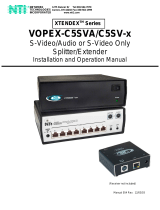
NOTE: THE PS/2 mouse connector has 6 pins, the 9D serial mouse connector has 9 pins.
MATING FACE OF FEMALE
6miniDIN PS/2 MOUSE
CONNECTOR 9D
Optional Materials
• A cable for each device to be connected to the VOPEX. The maximum length of these cables is 250 feet.
• VKEXT-xx or DKEXT-xx -Keyboard extension cable
• MMEXT-xx -9D serial mouse extension cable
• VEXT-xx -VGA video extension cable
• VKEXT-xx -PS/2 mouse extension cable
where: xx is the length of the cable in feet, and
MM indicates male-to-male connectors.
NOTE: PS/2 Keyboard or PS/2 mouse cables longer than 100 feet must have an AC power adapter. (Order VKEXT-xxx-
where xxx is between 101 and 500 feet. AC power adapter included).
Cables can be purchased from Network Technologies Inc by calling (330) 562-7070, or (800) RGB-TECH (800-742-8324), or by
visiting our website at http://www.nti1.com.
MATING FACE OF
MALE 9D SERIAL
MOUSE CONNECTOR
1
23
4
5
9
8
7
6
1
2
4
3
65

2
CONNECTING THE VOPEX TO THE CPU
1. Turn OFF power to the CPU that will be connected to the VOPEX before connecting or disconnecting any cables.
WARNING! If power to the CPU is not turned OFF before connecting or disconnecting cables, damage to the CPU
may result.
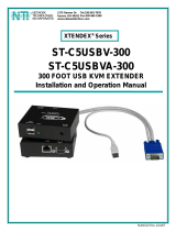
2. Connect the CPU to the VOPEX as follows (see Figures 1 and 2):
a) Connect a VEXT-3 cable from the video port of the CPU to the male 15HD port labeled "VGA CPU" on the VOPEX.
b) Connect a purple male 6 miniDIN connectors of the VVKINT-3-MM cable from the keyboard port of the CPU to the
female 6 miniDIN port labeled "KYBD CPU" on the VOPEX.
c) Connect the green male 6 miniDIIN connectors of the VVKINT-3-MM cable from the mouse port of the CPU to the port
labeled "MOUSE CPU" on the VOPEX.
3. Plug the VOPEX into an AC power outlet.
V V K I N T - 3 - M M
V G A
M u l t i - S c a n
M o n i t o r
2 1
4 3
6 5
2 1
4 3
6 5
K Y B D
C P U
M O U S E 2 M O U S E 1
M O U S E
C P U
2 1
4 3
6 5
2 1
4 3
6 5
M O U S E 4 M O U S E 3
K Y B D 4 K Y B D 3 K Y B D 2 K Y B D 1
V G A C P UV G A M O N 1V G A M O N 2V G A M O N 3V G A M O N 4
V E X T - 3
P C
F i g u r e 1
V O P E X - 4 K V I M - A
S u p p o r t i n g M o n i t o r , P S 2 M o u s e , a n d P S 2 K e y b o a r d
P S / 2 K e y b o a r d
P S / 2 M o u s e
K Y B D
C P U
M O U S E 4
M O U S E 3
K Y B D 4 K Y B D 3 K Y B D 2 K Y B D 1
V G A C P UV G A M O N 1V G A M O N 2V G A M O N 3V G A M O N 4
M O U S E 2 M O U S E 1 M O U S E C P U
F i g u r e 2
V O P E X - 4 K V M M - A
S u p p o r t i n g M o n i t o r , S e r i a l M o u s e , a n d P S 2 K e y b o a r d
D I N T - 6
V G A
M u l t i - S c a n
M o n i t o r
D K I N T - 6 - M M
V E X T - 6
S e r i a l M o u s e
P S / 2 K e y b o a r d
P C

3
Installing the Optional Monitor(s)
1. Plug all monitors into AC power outlets.
2. Turn OFF power to the monitors that will be connected to the VOPEX before connecting them.
3. Connect a monitor to the VGA MON1 port on the back of the VOPEX. See Figures 1 and 2.
Note: A monitor must be connected to the VGA MON1 port for the monitor device driver to function properly.
4. Connect any other monitors to any of the other VGA MON ports on the back of the VOPEX.
Installing the Optional Mouse(Mice)
1. Connect a mouse to the MOUSE1 port on the back of the VOPEX. See Figures 1 and 2.
2. Connect each mouse to a MOUSE port on the back of the VOPEX. Note which port number each user is attached to.
Installing the Optional Keyboard(s)
1. Connect a keyboard to the port labeled KYBD1 on the rear of the VOPEX. See Figures 1 and 2.
2. Connect the other keyboards to the back of the VOPEX, making sure that each user is connected to a Keyboard port and a
Mouse port with the same number.
MOUSE SPECIAL CONSIDERATIONS
NOTE: If the VOPEX is power-cycled with the CPU ON, the mouse driver must be reloaded for mice to function properly.
PS/2 MOUSE
1. Hot plugging limitations
A. Any mouse to be emulated must be connected to the first populated port at VOPEX power-up. e.g. If at a later time the
user wants to hot-plug 3-button mice, a 3-button mouse must have been connected in the first position at VOPEX power-
up.
B. If no mice were connected at power-up, VOPEX will default to standard 2-button mode.
2. ALPS Glidepoint
A. For “taps” function to work properly, ALPS Glidepoint must be in the first populated port on the VOPEX at power-up and
ALPS Mouse Driver must be used.
B. Some Microsoft mice may conflict with ALPS Glidepoint. If a problem occurs, connect ALPS to first populated port and
use a regular Microsoft mouse driver. NOTE: ”taps” will not function in this configuration.
3. Microsoft Ballpoint
A. Do not connect Ballpoint to the first populated port if other types of mice are to be used in the VOPEX. If Ballpoint is in
the first populated port, all other mice must also be Ballpoints.
B. At least one Ballpoint must be connected to VOPEX when powering up in order for hot-plugging to work for other
Ballpoints.
4. 3-button Mice
A. A 3-button mouse must be connected to the first populated port for any mice to work as 3-button.
5. Microsoft IntelliMouse
A. All mice connected to VOPEX must be IntelliMouse to be able to use the IntelliMouse.
B. The IntelliMouse cannot be hot-plugged.
9D SERIAL MOUSE
1. Hot-plugging
A. If no mice were connected at power-up, Mouse Systems mode will be emulated and hot-plugging Microsoft mice will not
function properly.
B. All mice connected must be set to the same mode. (Either all Mouse Systems or all Microsoft).
POWER-UP SEQUENCE
Note: Any cable longer than 100 feet for the keyboard requires an AC adapter. If using a COMPAQ keyboard, the
adapter and the VOPEX must be powered up at the same time!
1. Turn ON power to the VOPEX.
2. Turn ON power to the monitor(s).
Note: The monitor(s) MUST be turned ON before the CPU.
3. Turn ON power to the CPU.
Keyboards and mice are powered by the VOPEX.
POWER-DOWN SEQUENCE
1. Turn OFF power to the CPU.
2. Turn OFF power to the VOPEX.

4
DIAGNOSTIC INFORMATION
At power up, the VOPEX uses the mode LEDs on the front panel to report some status. The sequence of events is as follows:
1. When unit is first powered, the LED state is indeterminate.
2. All LEDs are turned OFF, then flashed ON and OFF to indicate processor activity.
3. One LED for each keyboard detected is flashed ON and OFF.
4. One LED for each mouse detected is flashed ON and OFF.
5. The LEDs are left in the proper mode status (see “MODES OF OPERATION ”).
MODES OF OPERATION
This VOPEX has three basic modes of operation: INSTANT AUTO. DELAYED AUTO, and USERx. Press the “MODE” button on
the front panel of the VOPEX to select the desired mode per the chart below:
INSTANT AUTO: Any user can gain immediate access to the CPU by pressing a key or moving a mouse, unless another user is
active.
DELAYED AUTO: Any user can gain access as long as no user LEDs are currently illuminated. When the active user’s
keyboard/mouse are idle for at least 5 seconds, user LED goes out and anyone can then gain access.
USERx: The VOPEX has a user mode for each port. When any user mode is selected, that LED remains ON and all other users
are locked out until the mode is changed by pressing the MODE button.
Monitor
All monitors connected to the VOPEX display exactly the same information. For example, if the user connected to Port 3 is
inputting data, then all users connected to the VOPEX see what that user is entering.
STATUS OF LED’S MODE
ALL USER LED’s ON INSTANT AUTO
ALL LIGHTS OFF DELAYED AUTO
USER 1 ON, ALL OTHERS OFF USER1 ONLY
USER 2 ON, ALL OTHERS OFF USER2 ONLY
USER 3 ON, ALL OTHERS OFF USER3 ONLY
USER 4 ON, ALL OTHERS OFF USER4 ONLY
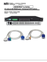
TECHNICAL SPECIFICATIONS
15HD Monitor
1. Red Video 5. TST 9. Unused 13. H Sync
2. Green Video 6. Red Ground 10. Ground 14. V Sync
3. Blue Video 7. Green Ground 11. ID0 15. ID3
4. ID2 8. Blue Ground 12. ID1
5 DIN keyboard 9DB Serial Mouse 6 miniDIN PS2 Mouse
or PS2 Keyboard
1. Clock 1. Unused 6. Unused 1. Data
2. Data 2. RX 7. RTS 2. Unused
3. Unused 3. TX 8. Unused 3. Ground
4. Ground 4. DTR 9. Unused 4. +5V
5. +5V 5. Ground 5. Clock
6. Unused
M a t i n g f a c e o f a
1 5 H D f e m a l e
V G A V I D E O
4
2
3
5 1
1 0
9 8 6
7
1 5
1 4
1 3
1 2
1 1
1
2
4
3
6
5
M a t i n g f a c e
o f f e m a l e
6 p i n m i n i D I N
1
M a t i n g f a c e
o f 9 D B m a l e
2
3
4
5
6
7
8
9
5
3
2
4
1
M a t i n g f a c e o f
a 5 D I N f e m a l e

5
TROUBLESHOOTING
If any problems are experienced with the VOPEX switch, follow the steps below to see if the problem(s) can be easily
corrected:
1. Verify that all cables are securely connected.
2. Verify that a monitor is connected to Port 1.
3. If a user has both a keyboard and mouse, verify that they are connected to a Keyboard port and Mouse port with the same
port number.
4. If a cable is disconnected:
a) Turn OFF power to the CPU.
b) Turn OFF power to the VOPEX.
c) Connect the cable.
d) Go through the power-up sequence described on page 3.
If trouble is still being experienced, a solution may be found in the Frequently Ask Questions (FAQ’s) section of our website at
http://www.nti1.com or please call us directly at (800) 742-8324 (800-RGB-TECH) or (330) 562-7070 and we will be happy to
assist in any way we can.
SERIAL NO.:
DATE:
INSPECTED BY:
VOPEX-2KV-A PS/2 keyboard + VGA 2 port
VOPEX-2KIM-A PS/2 keyboard + PS/2 mouse 2 port
VOPEX-2KMM-A PS/2 keyboard + serial mouse 2 port
VOPEX-2KVIM-A PS/2 keyboard + PS/2 mouse + VGA 2 port
VOPEX-2KVMM-A PS/2 keyboard + serial mouse + VGA 2 port
VOPEX-4KV-A PS/2 keyboard + VGA 4 port
VOPEX-4KIM-A PS/2 keyboard + PS/2 mouse 4 port
VOPEX-4KMM-A PS/2 keyboard + serial mouse 4 port
VOPEX-4KVIM-A PS/2 keyboard + PS/2 mouse + VGA 4 port
VOPEX-4KVMM-A PS/2 keyboard + serial mouse + VGA 4 port
/