Page is loading ...

Man014 Rev. 9/11/18
600 FOOT EXTENDERS
Installation and Operation Manual
XTENDEX
®
Series
ST-C5KVM-600
PS/2 KVM Extender

i
Crimp-on
Solder
terminal
TRADEMARK
XTENDEX is a registered trademark of Network Technologies Inc in the U.S. and other countries.
COPYRIGHT
Copyright © 2003, 2018 by Network Technologies Inc. All rights reserved. No part of this publication may be reproduced, stored
in a retrieval system, or transmitted, in any form or by any means, electronic, mechanical, photocopying, recording, or otherwise,
without the prior written consent of Network Technologies Inc, 1275 Danner Drive, Aurora, Ohio 44202.
CHANGES
The material in this guide is for information only and is subject to change without notice. Network Technologies Inc reserves the
right to make changes in the product design without reservation and without notification to its users.
Note: Shielded
CAT 5,5e, or 6 cable must be used to connect to LOCAL and REMOTE units in order to meet CE emission
and immunity requirements.
Note: CATx connection cable used between NTI XTENDEX Series Local and Remote or any XTENDEX Series products
should not be run underground, outdoors or between buildings.
WARNING: Outdoor or underground runs of CATX cable could be dangerous and will void the warranty.
WARNING: The CATx connection cable used between NTI XTENDEX Series Local and Remote or any XTENDEX Series
products must be wired straight through (pin 1 to pin 1, pin 2 to pin 2, etc.) The use of a CROSSOVER CABLE will
damage the extender and void your warranty.
CE Statement
We, Network Technologies Inc, declare under our sole responsibility that the ST-C5KVM-600, STC5KVMRS-600, STC5KVMA-
600, ST-C5V-600, STC5VRS-600 and ST-C5VA-600 is in conformity with European Standard EN55022.
External Ground
This product is equipped with grounding hardware to prevent interference
from sources of electrical noise that could interfere with the normal operation
of the XTENDEX or damage it. Use either the crimp-on lug or solder terminal
to secure a properly grounded wire (connected to earth ground) to the
XTENDEX.
Failure to make this connection may result in poor video quality at the
connected monitor(s).

ii
TABLE OF CONTENTS
Introduction....................................................................................................................................................................1
Materials.........................................................................................................................................................................2
Features and Functions................................................................................................................................................4
Limitations .....................................................................................................................................................................6
Preparation for Installation...........................................................................................................................................7
Installation......................................................................................................................................................................8
Installing The Local Unit (models with VGA video connectors)..................................................................................8
Installing the Local Unit (models with only KM connectors)......................................................................................10
Connect The CATx Cable..........................................................................................................................................11
Installing The Remote Unit (models with VGA video connectors).............................................................................11
Installing The Remote Unit (models with only KM connectors).................................................................................13
Connect the CATx cable............................................................................................................................................13
Models With One Remote.......................................................................................................................................13
Models With Two Remotes.....................................................................................................................................14
Plug-in and Boot Up...................................................................................................................................................15
Video Quality ...............................................................................................................................................................16
Command Mode........................................................................................................................................................17
Enter Command Mode............................................................................................................................................17
General Video Quality Adjustment ......................................................................................................................17
Update DDC at Remote.......................................................................................................................................17
Update DDC at Local...........................................................................................................................................17
Mix DDC ..............................................................................................................................................................18
Reset Defaults.....................................................................................................................................................18
Exit Command Mode ..............................................................................................................................................18
Other DDC Support ...................................................................................................................................................18
Automatic EDID Updates........................................................................................................................................18
Manual EDID Capture.............................................................................................................................................19
More About DDC .................................................................................................................................................20
Technical Specifications ............................................................................................................................................21
Interconnection Cable Wiring Method ......................................................................................................................22
Troubleshooting..........................................................................................................................................................23
Index.............................................................................................................................................................................24
Warranty Information..................................................................................................................................................24
TABLE OF FIGURES
Figure 1- Connect the Local Unit with VGA video and RS232 support to the CPU............................................................................8
Figure 2- Connect the Local Unit with Audio support to the CPU ......................................................................................................9
Figure 3- Connect the local user to the XTENDEX Local Unit...........................................................................................................9
Figure 4- Connect stereo speakers to XTENDEX Local Unit with audio support.............................................................................10
Figure 5- Connect Local Unit with only keyboard and mouse support.............................................................................................10
Figure 6- Connect CATx cable to Local Unit....................................................................................................................................11
Figure 7- Connect the Extended Components to the Remote Unit..................................................................................................12
Figure 8- Connect speakers to the Remote Unit..............................................................................................................................12
Figure 9- Connect keyboard and mouse to Remote Unit.................................................................................................................13
Figure 10- Connect the CATx cable to the Remote Unit..................................................................................................................13
Figure 11- Connect CATx cables between Local and Remote Units ...............................................................................................14
Figure 12- Connect the AC adapter to the Remote Unit ..................................................................................................................15
Figure 13- Buttons for video quality adjustment...............................................................................................................................16
Figure 14- DDC Update Button on Local with Dual Remote Support...............................................................................................19
Figure 15- Connect remote monitor for EDID capture .....................................................................................................................19
Figure 16- View looking into RJ45 female........................................................................................................................................22

NTI XTENDEX 600 Foot Extenders
1
INTRODUCTION
The XTENDEX Series CAT5 Extender (XTENDEX) is designed to enable one CPU to be controlled by two users, one local and
one remote. The remote user can be located as much as 600 feet away from a PS/2 CPU via Category 5/5e/6 (CATx)
unshielded twisted-pair cable. The local user will be located near the CPU.
Options:
Local Supporting Two Remotes- The XTENDEX series 600 foot PS/2 extender is available supporting two Remote Units from a
single Local Unit if needed. See chart below for available models and features. When ordering the XTENDEX with dual Remote
support, Remote Units are ordered separately.
The XTENDEX Series Extender is extremely simple to install and has been thoroughly tested to insure reliable performance.
Through the use of Category 5\5e\6 cable it is possible to economically increase the flexibility of a computer system. Here are
some of the features and ways this can benefit any workplace:
Allows the placement of computer peripherals (monitor, keyboard, and mouse) in a location where
only these parts are needed without having the CPU there too, taking up valuable space
Allows a PS/2 CPU to be accessed by both a local and remote user (up to 600 feet away)(most models-see chart below)
Compatible with XGA and VGA systems
Provides crisp and clear resolution up to 1024 x 768 @ 600 feet (see page 21 for more details)
Compatible with all NTI switches and splitters, enabling the joining of products to create a system that
satisfies all networking needs
Video quality adjustment, for varying lengths of cable, is automatic (most models, see below and
page 20) providing optimum image quality
Audio frequency response is 20Hz to 20Khz, + 1dB (models with audio support only)
Digital transmission of audio signals reduces any loss in quality (models with audio support only)
This manual covers each of the XTENDEX Series CAT5-600 Extender models offered. Some features described in this manual
are available in some models and not in others. The chart below shows the features supported in each:
Model Video Kybd/ Mse
Support
Audio
Support
# of Remotes
Supported
RS232
Support
Video Quality
Adjustment
ST-C5KVM-600
VGA Yes No 1 No Automatic
ST-C5KVMA-600
VGA Yes Yes 1 No Automatic
ST-C5KVMRS-600
VGA Yes No 1 Yes Automatic
ST-C5V-600
VGA No No 1 No Manual
ST-C5VA-600
VGA No Yes 1 No Automatic
ST-C5VRS-600
VGA No No 1 Yes Automatic
ST-2C5V-L-600
VGA No No 2 No Manual
ST-2C5VA-L-600
VGA No Yes 2 No Automatic
ST-C5KVMRS-600-SCI
VGA Yes No 1 Yes Manual
ST-C5KM-600
NO On Remote
only
No 1 No Not Applicable
Note: Models shaded in blue (ST-2C5V(A)-L-600) provide Remote Unit-only support for devices, no Local Unit support.

NTI XTENDEX 600 Foot Extenders
2
MATERIALS
Materials supplied with ST-C5xxxx-600:
NTI XTENDEX Local Unit
NTI XTENDEX Remote Unit
2- 120VAC or 240VAC at 50 or 60Hz-9VDC/1.0A AC Adapters (only 1 ST-C5KM-600)
Materials supplied with ST-2C5xxxx-L-600:
NTI XTENDEX Local Unit
1- 120VAC or 240VAC at 50 or 60Hz-9VDC/1.0A AC Adapter
Additional materials may need to be ordered, depending upon the configuration:
CAT5/5e/6 unshielded twisted-pair cable(s) terminated with RJ45 connectors wired straight thru- pin 1 to pin 1, etc. (see pg.
8 for proper EIA/TIA 568 B wiring method)
Note: Shielded CAT5, 5e, or 6 cable must be used to connect to LOCAL and REMOTE units in order to meet CE emission
requirements.
Cable(s) needed if Local Unit will be located further than 15" from the CPU
Model Cable(s) needed
ST-C5KVM-600 VKMEXT-xx (xx= 3/6/10/15/25/35/50/75/100 feet)
ST-C5KVMRS-600 VKMEXT-xx and DINT-xx
ST-C5KVMA-600 VKMEXT-xx and SA-xx-MF
ST-C5V-600 VEXT-xx
ST-C5VRS-600 VEXT-xx and DINT-xx
ST-C5VA-600 VEXT-xx and SA-xx-MF
ST-C5KM-600 VVKINT-xx or VVKEXT-xx
The chart above also applies to Local Unit models with support for two remotes.
Cables Lengths Available
Cable xx= Length in feet
VKMEXT-xx 3/6/10/15/25/35/50/75/100
VEXT-xx 3/6/10/15/25/35/50/75/100
DINT-xx 6/10/15
SA-xx-MF 6/12/25/50
VVKINT-xx 3/6/10/15/25
VVKEXT-xx 35/50/75/100
Legend:
xx= 3, 6, 10, 15 or 25 foot length
MM= cables have male connectors on both ends (except for the DB9) and are only used with Local Units
Note: If two users will be connected (one local and one remote), two of the cables without the “MM”
(i.e. VMCTINT-xx) will be needed.
Contact your nearest NTI distributor or NTI directly for all of your KVM needs at 800-RGB-TECH (800-742-8324) in US & Canada
or 330-562-7070 (Worldwide) or at our website at http://www.networktechinc.com and we will be happy to be of assistance.

NTI XTENDEX 600 Foot Extenders
3

NTI XTENDEX 600 Foot Extenders
4
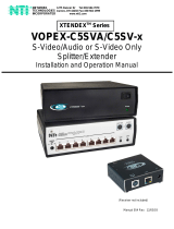
FEATURES AND FUNCTIONS
1. Green LED- power indicator- illuminates when power has been supplied to the unit
2. Yellow LED- traffic indicator- illuminates when there is communication between the local and remote units.
3. Cat 5- RJ45 female- for connecting the CAT 5 cable
4. Video Connector- 15HD female- for connecting the local user's VGA monitor
5a. RS232 Connector- 9D male- for connecting the local user's touchscreen monitor (models with RS232
support only)
5b. Audio Jack- 3.5mm stereo audio jack- for connecting to local speakers (models with audio support only)
6. Mouse Connector- green female 6 miniDIN- for connecting the local user's mouse
7. Keyboard Connector- purple female 6 miniDIN- for connecting the local user's keyboard
8. Video Connector- blue 15HD male- for connecting to the video port on the CPU or KVM switch
9. Mouse Connector- green male 6 miniDIN- for connecting to the mouse port on the CPU or KVM switch
10. Keyboard Connector- purple male 6 miniDIN- for connecting to the keyboard port on the CPU or KVM switch
11a. RS232 Connector- light gray 9D female- for connecting to the RS232 port on the CPU or KVM switch
(models with RS232 support only)
11b. Audio Plug- 3.5mm stereo audio plug- for connecting to CPU audio line out (models with audio support
only)
12. Keyboard Connector- purple female 6 miniDIN- for connecting the remote user's keyboard
13. Mouse Connector- green female 6 miniDIN- for connecting the remote user's mouse
14a. RS232 Connector- 9D male- for connecting the remote user's touchscreen monitor (models with RS232
support only)
14b. Audio Jack- 3.5mm stereo audio jack- for connecting to remote speakers (models with audio support only)
15. 9VDC- 1.0A- connection jack for the AC adapter
16. Video Connector- 15HD female- for connecting the remote user's monitor
17. Buttons- for manually adjusting video quality (models ST-C5V-600 and ST-C5KVMRS-600-SCI only)
18. DDC Update- Button used to send updated EDID to the graphics card in the CPU (supported models only)
Note: The 15HD female port on the ST-2C5V(A)-L-600 is used for EDID capture only (see page 18).

NTI XTENDEX 600 Foot Extenders
5

NTI XTENDEX 600 Foot Extenders
6
LIMITATIONS
Hot-plugging of devices is supported provided devices were originally connected at power-up.
In order for two users to share a PS/2 CPU, the user in control must pause for at least 3 seconds before another user can
take control. After the 3 second pause, either user can take control of the CPU.
For models with RS232 support:
The RS232 ports on the Local and Remote Units will support serial devices other than touchscreen monitors as follows:
2 simple devices (i.e. mice) connected to each
unit, or
1 complex device (i.e. serial modem, RS232 command port on an NTI switch) connected to
either
the Remote or Local Unit.
In order for two users to share a PS/2 CPU, the user in control must pause for at least 3 seconds before another user can
take control. After the 3 second pause, either user can take control of the CPU.
The RS232 port supports all baud rates up to 56K bits per second and the attached CPU must be configured accordingly.
For models with audio support:
The audio input of the XTENDEX with audio support is compatible with the following standard CPU audio outputs:
Line out - typically lime green in color
Speaker out- typically orange in color
Headphone out- typically located on the CD-ROM
The audio output of the XTENDEX with audio support is compatible with self-powered stereo speakers.

NTI XTENDEX 600 Foot Extenders
7
Crimp-on
Solder
terminal
PREPARATION FOR INSTALLATION
Locations should be chosen for the monitors, mice, and keyboards that also have space to connect the Remote and Local
Units within the distance provided by the cables. If extension cables are needed, contact NTI for the cables required.
The CATX cables must be run to the locations where the Remote and Local Units will be connected. Be careful to route the
cables away from any sources of magnetic fields or electrical interference that might reduce the quality of the video signal
(i.e. AC motors, welding equipment, etc.).
All cables should be installed in such a way that they do not cause stress on their connections to the equipment. Extended
lengths of cable hanging from a connection may interfere with the quality of that connection. Secure cables as needed to
minimize this.
Properly shut down and disconnect the power from the CPU and monitors to be separated. If other equipment is involved
whose connections are being interrupted, be sure to refer to the instruction manuals for that equipment for proper
disconnection and re-connection procedures before proceeding.
Local and Remote Units should be grounded through either a display or source that uses a 3-prong power cord. If only one
unit is grounded, shielded CAT5 cable should be used.
Note: CATX connection cable used between NTI XTENDEX Series Local and Remote or any XTENDEX Series products
should not be run underground, outdoors or between buildings.
WARNING: Outdoor or underground runs of CATX cable could be dangerous and will void the warranty.
External Ground
This product is equipped with grounding hardware to prevent interference
from sources of electrical noise that could interfere with the normal operation
of the XTENDEX or damage it. Use either the crimp-on lug or solder terminal
to secure a properly grounded wire (connected to earth ground) to the
XTENDEX.
Failure to make this connection may result in poor video quality at the
connected monitor(s).

NTI XTENDEX 600 Foot Extenders
8
INSTALLATION
Installing The Local Unit (models with VGA video connectors)
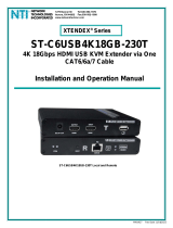
1. Plug the cables of the Local Unit into the back of the CPU. (See Figure 1.)
a) Connect the blue 15HD cable end to the VGA port on the back of the CPU.
b) Connect the purple 6 pin miniDIN cable end with the keyboard symbol
on it to the keyboard port on the back of the CPU. (KVM models only)
c) Connect the green 6 pin miniDIN cable end with the mouse symbol
on it to the mouse port on the back of the CPU. (KVM models only)
Figure 1- Connect the Local Unit with VGA video and RS232 support to the CPU
d) If the Local Unit has RS232 support, connect the light gray 9D cable end to the RS232 port on
the back of the CPU.
e) If the Local Unit has Audio support, connect the black 3.5mm stereo plug into the "line out",
"spkr", or "headphones" jack on the back of the CPU. (See Figure 2)
Notes:
If all 3 jacks are available, use the jack marked "line out".
The "line out" jack is typically lime green and may be marked with this symbol
The "spkr" jack is typically orange, and may be marked with this symbol
The "headphones" jack may be marked with this symbol
(Mouse)
(Keyboard)
ST-C5KVMRS-600 Local Unit
(Front View)
15HD Female
Video Connector
6 pin miniDIN
Male Connector
(GREEN-MOUSE)
(PURPLE-KEYBOARD)
(BLUE- VIDEO)
PS/2 CPU
6 pin miniDIN
Female
Connector
DEVICE
CONNECTORS
VIDEO
CONNECTOR
15HD Male
Video Connector
(LIGHT GRAY- RS232)
9D Female Connector
9D Male
RS232 Connector
SERIAL
CONNECTOR
-
+
NTI
R
Netw ork Tec hnolo gies Inc
XTENDEX

NTI XTENDEX 600 Foot Extenders
9
Figure 2- Connect the Local Unit with Audio support to the CPU
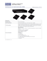
2. Make connections for a local user (see Figure 3)
a) Connect the cable from the local user's VGA monitor to the female 15HD port on the Local Unit.
b) Connect the local user's keyboard to the purple 6 pin miniDIN female port on the Local Unit.
c) Connect the local user's mouse to the green 6 pin miniDIN female port on the Local Unit.
Figure 3- Connect the local user to the XTENDEX Local Unit
VGA
Multi-Scan
Touch-screen
Monitor
PS/2 KEYBOARD PS/2 MOUSE
15HD Female
Video Connector
Front View of
Local Unit
ST-C5KVMRS-600 Local Unit (Front and Rear View)
9D Male
RS232 Connector
Rear View of Local Unit
L
ocal User's Ke
y
board, Monitor, and Mouse
6 pin miniDIN
Female Connector
NTI
R
Net work Tec hnol ogies Inc
XTENDEX
- +
ST-C5KVMA-600 Local Unit
(Front View)
(GREEN-MOUSE)
(PURPLE-KEYBOARD)
(BLUE- VIDEO)
PS/2 CPU
- +
NTI
R
Netw ork Tec hnolo gies Inc
XTENDEX
(BLACK- AUDIO)
3.5mm Stereo Plug
AUDIO CONNECTOR
line
out
ONE WILL BE MARKED "line
out" ,"spkr", "headphones"
OR WITH THIS SYMBOL

NTI XTENDEX 600 Foot Extenders
10
d) If the Local Unit has RS232 support, connect the local user's RS232 cable from a touch screen
monitor to the 9D male port on the Local Unit.
e) If the Local Unit has audio support, connect the cable from the local speakers to the 3.5mm
stereo audio jack on the Local Unit. (See Figure 4)
Figure 4- Connect stereo speakers to XTENDEX Local Unit with audio support
Installing the Local Unit (models with only KM connectors)
1. Plug the cables of the Local Unit into the back of the CPU. (See Figure 5)
a) Connect the green 6 pin miniDIN cable end with the mouse symbol on it to the mouse port on the back of the CPU.
b) Connect the purple 6 pin miniDIN cable end with the keyboard symbol on it to the keyboard port on the back of the
CPU.
Figure 5- Connect Local Unit with only keyboard and mouse support
Front View
ST-C5KVMA-600 Local Unit
NTI
R
Netw ork Tec hnolo gies Inc
XTENDEX
- +
3.5mm Stereo
Audio Jack
Stereo
Speakers
ST-C5KM-600 Local Unit
(Front View)
(GREEN-MOUSE)
(PURPLE-KEYBOARD)
PS/2 CPU
NTI
R
Netw ork Tec hnolo gies Inc
XTENDEX
6 pin miniDIN
Female Connector
DEVICE
CONNECTORS
6 pin miniDIN
Male Connector

NTI XTENDEX 600 Foot Extenders
11
Connect The CATx Cable
Connect the CATx cable to the “Cat 5” port on the Local Unit.
(See Figure 6.) When properly inserted the cable end should
snap into place.
Note: If an RJ45 wall outlet is being used, connect the other
end of the extension cable to the RJ45 wall outlet.
WARNING: Never connect the XTENDEX to an
Ethernet card, Ethernet router, hub or switch or other Ethernet
RJ45 connector of an Ethernet device. Damage to devices
connected to the Ethernet may result.
Figure 6- Connect CATx cable to Local Unit
WARNING: The CATx connection cable used between NTI XTENDEX Series Local and Remote or any XTENDEX Series
products must be wired straight through (pin 1 to pin 1, pin 2 to pin 2, etc.) The use of a CROSSOVER CABLE will
damage the extender and void your warranty.
Installing The Remote Unit (models with VGA video connectors)
1. Position the Remote Unit such that the CATx cable, the monitor cable, device cables, and the AC
adapter power connector can each reach the Remote Unit without putting strain on the cables.
2. Connect the monitor cable to the female 15HD video connector on the Remote Unit.
3. Connect the device(s) to the Remote Unit (see Figure 7)(KVM models only).
a) Connect the keyboard to the purple female 6 pin miniDIN connector on the Remote Unit.
b) Connect the mouse to the green female 6 pin miniDIN connector on the Remote Unit.
4. If the Remote Unit has RS232 support, connect the remote user's RS232 cable from a touch
screen monitor to the 9D male port on the Remote Unit.
5. If the Remote Unit has audio support, connect the cable from the remote speakers to the 3.5mm
stereo audio jack on the Remote Unit. (See Figure 7)
!

NTI XTENDEX 600 Foot Extenders
12
Figure 7- Connect the Extended Components to the Remote Unit
Figure 8- Connect speakers to the Remote Unit
9D Male
RS232 Connector
Front View of
Remote Unit
Rear View of Remote Unit
VGA
Multi-Scan
Monitor
PS/2 KEYBOARD PS/2 MOUSE
15HD Female
Video Connector
Remote User's Keyboard, Monitor, and Mouse
6 pin miniDIN
Female Connector
NTI
R
Net work Techno lo gies Inc
XTENDEX
- +
ST-C5KVMRS-600 Remote Unit (Front and Rear View)
Front View
ST-C5KVMA-600 Remote Unit
NTI
R
Netw ork Tec hnolo gies Inc
XTENDEX
- +
3.5mm Stereo
Audio Jack
Stereo
Speakers

NTI XTENDEX 600 Foot Extenders
13
Installing The Remote Unit (models with only KM connectors)
1. Position the Remote Unit such that the CATx cable, the keyboard cable, mouse cable and power supply cable can each
reach the Remote Unit without putting strain on the cables.
2. Connect the keyboard to the purple female 6 pin miniDIN connector on the Remote Unit.
3. Connect the mouse to the green female 6 pin miniDIN connector on the Remote Unit.
Figure 9- Connect keyboard and mouse to Remote Unit
Connect the CATx cable
Models With One Remote
Make sure the CATx cable has been installed in accordance with the “Preparation for Installation”
instructions on page 3. Connect the CATx cable to the “Cat 5” port on the Remote Unit. (See Figure 10.)
When properly inserted the CATx cable end should snap into place.
Note: If an RJ45 wall outlet is being used, connect the other end of the extension cable to the RJ45 wall outlet.
WARNING: Never connect the XTENDEX to an Ethernet card, Ethernet
router, hub or switch or other Ethernet RJ45 connector of an Ethernet device.
Damage to devices connected to the Ethernet may result.
WARNING: The CATx connection cable used between NTI XTENDEX Series Local
and Remote or any XTENDEX Series products must be wired straight through (pin 1
to pin 1, pin 2 to pin 2, etc.) The use of a CROSSOVER CABLE will damage the
extender and void your warranty.
Figure 10- Connect the CATx cable to the Remote Unit
!
Front View
PS/2 KEYBOARDPS/2 MOUSE
Remote User's Keyboard and Mouse
6 pin miniDIN
Female Connector
NTI
R
Netw ork Tec hnol ogie s Inc
XTENDEX
ST-C5KM-600 Remote Unit
- +

NTI XTENDEX 600 Foot Extenders
14
Models With Two Remotes
Connect the CATx cable from each
Remote Unit being used to the “CAT5
Remote 1” and “CAT5 Remote 2”
ports on the rear of the Local Unit
(see Figure 11). When properly
inserted the cable end should snap
into place.
Make the remaining connections to
the Remote Units as described
beginning on page 11.
WARNING: Never connect the
XTENDEX to an Ethernet card, Ethernet
router, hub or switch or other Ethernet
RJ45 connector of an Ethernet device.
Damage to devices connected to the
Ethernet may result.
WARNING: The CATx connection cable
used between NTI XTENDEX Series Local
and Remote or any XTENDEX Series
products must be wired straight through
(pin 1 to pin 1, pin 2 to pin 2, etc.) The use
of a CROSSOVER CABLE will damage the
extender and void your warranty.
Figure 11- Connect CATx cables between Local and Remote Units
!

NTI XTENDEX 600 Foot Extenders
15
Plug-in and Boot Up
1. Plug the power cord from the monitor into the power outlet.
2.
Connect each AC adapter power connector to the 9VDC ports on the Remote and Local Units Plug each AC adapter into a
power outlet. The green LED on the RJ45 connector of both the Remote and Local Units should illuminate, indicating that a
proper power connection has been made to them. (See Figure 12.)
Figure 12- Connect the AC adapter to the Remote Unit
3. Turn ON the CPU and Monitor. They should each react as if they were directly connected to each other.
Note: The Traffic LED on each RJ45 connector will illuminate anytime data traffic is passing between the Local and
Remote Units, indicating proper CAT5 cable connection and communication. (See Figure 12)
Green Power LED
9 VDC
Adapter
ADAPTER
Barrel
(Inside
barrel)
(Outside
barrel)
Power Connector
2.1 mm x 5.5 mm Female
9VDC @ 1.0A OUTPUT
Yellow Traffic LED
Rear View of Remote Unit
ST-C5KVM-R-600

NTI XTENDEX 600 Foot Extenders
16
VIDEO QUALITY
Automatic Video Quality Adjustment (see chart on page 1)
Video quality adjustment is done automatically to assure the image is as clear as possible.
Note: When the cable is longer than 300 feet some colored lines can be seen at the black-to-white transitions. This is a
normal behavior and is caused by the different twisting rates of each pair of wires in the CATx cable.
Manual Video Quality Adjustment (see chart on page 1)
It is possible that on initial startup the image on the monitor will not be as crisp as the image normally is. This is due to the
frequency characteristics of the CATx cable. It may be necessary to press the "+" or "-" buttons (see Figure 13) until the image
is crisp and clear. Press the "+" button if the image is not crisp and clear enough. Press the "-" button if the image has been
over-corrected (such that horizontal lines appear to trail or shadow at the edge of an open window). A momentary press of either
button will make a minor change in the image. If either button is pressed and held, the changes made will be gradual and
continuous. Ultimately, the image quality should improve to a satisfactory level. Once the adjustment is made, it should not be
necessary to change it again, as the new settings are stored in memory and become the default settings with each startup.
Note: When the cable is longer than 300 feet some colored lines can be seen at the black-to-white transitions. This is a
normal behavior and is caused by the different twisting rates of each pair of wires in the CATx cable.
Figure 13- Buttons for video quality adjustment
If the image still lacks definition, configuration adjustments may need to be made to the attached video display equipment. This is
a problem most often seen in LCD displays. Check the manual for the equipment having the poor display and look for an "auto-
adjust" or "auto-configure" feature. Once this is done, you may need to repeat the Video Quality Adjustment procedure
described above to achieve the best image.
Press using pen or other
pointed object to improve
screen image
Side view of ST-C5V-600 Remote Unit
CAT5
NTI
R
ST-C5V-600M
XTENDEX
R
V
+
_
_
REMOTE UNIT
Front View
ST-C5V-600M
Remote Unit

NTI XTENDEX 600 Foot Extenders
17
Command Mode
Depending upon your unit’s date of manufacture, models ST-C5KVM-600, ST-C5KVMA-600 and ST-C5KVMRS-600 may be
enabled with a Command Mode feature to perform the following:
fine adjustment of the general video quality
update DDC information between the monitor(s) and CPU
Most of the video quality adjustment is automatic at power ON, but if some adjustment is necessary, this can be done using the
keyboard attached to the Remote Unit.
DDC information allows the CPU to detect the video capability of your monitor by transferring EDID data from your monitor to the
CPU. DDC information can be updated from either the keyboard at the Local Unit, or at the Remote Unit.
To determine if your extender has this feature, try entering Command Mode (below) from the keyboard attached to the Remote
or Local Unit. If Command Mode is present, the three keyboard LEDs (NumLock, CapsLock, and ScrollLock) will blink at the
same time to indicate entrance into Command Mode. If the feature is not present, then the section “Automatic EDID Updates”
under “Other DDC Support” applies to your KVM extender.
Enter Command Mode
The user can enter Command Mode using any of three different methods;
Method 1 (Effective from the Remote or Local Unit)
1. Press and hold the left <Shift> key
2. Press the right <Shift> key
3. Release both keys
Method 2 (Effective from the Remote Unit only)
Press and release the <Scroll Lock> key twice fast (press twice within 1 second)
Method 3 (Effective from the Remote Unit only)
Press and release the left <Shift> key twice fast, then press and release the <Esc> key once , all within 2
seconds
The three keyboard LEDs (NumLock, CapsLock, and ScrollLock) will blink at the same time to indicate entrance into Command
Mode.
General Video Quality Adjustment
Command Mode opens into General Video Quality Adjustment mode. To fine tune the general video quality, press the <Left
Arrow> or <Right Arrow> keys until the desired improvement in the display has been achieved.
Note: General Video Quality Adjustment mode is provided to improve video quality at the remote monitor. Executing this
mode from Command Mode when using the keyboard attached to the local unit will have no effect.
Update DDC at Remote
To update DDC information based on the monitor connected to the Remote Unit, press <D> to enter Remote DDC information.
The CapsLock LED will illuminate solid, the NumLock and ScrollLock LEDs will be OFF . Press the < Left Arrow> or <Right
Arrow> key to cause DDC information to be updated. When the update is complete (less than one second), the unit will return to
General Video Quality Adjustment mode (the three keyboard LEDs will blink at the same time).
Update DDC at Local
To update DDC information based on the monitor connected to the Local Unit, press <C> to enter Local DDC information. The
CapsLock LED will illuminate solid, the NumLock and ScrollLock LEDs will be OFF . Press the < Left Arrow> or <Right
Arrow> key to cause DDC information to be updated. When the update is complete (approximately seven seconds), the unit will
return to General Video Quality Adjustment mode (the three keyboard LEDs will blink at the same time).
Note: It is recommended that the monitors connected to the Remote and Local units be of the same make and model.
/