Page is loading ...


inBOX 24 / inBOX 20
http://www.zennio.com Technical Support: http://support.zennio.com
2
CONTENTS
Contents ........................................................................................................................................ 2
Document Updates ....................................................................................................................... 3
1 Introduction .......................................................................................................................... 4
1.1 inBOX 24 / inBOX 20 ......................................................................................................... 4
1.2 Installation ........................................................................................................................ 5
1.3 Start-Up and Power Loss .................................................................................................. 6
2 Configuration......................................................................................................................... 7
2.1 General ............................................................................................................................. 7
2.2 Inputs (Only inBOX 24) ..................................................................................................... 9
2.2.1 Binary Input .............................................................................................................. 9
2.2.2 Temperature Probe ................................................................................................ 10
2.2.3 Motion Detector .................................................................................................... 10
2.3 Outputs........................................................................................................................... 11
2.3.1 Manual Control ...................................................................................................... 11
2.4 Logic Functions ............................................................................................................... 15
2.5 Thermostats (Only inBOX 24) ......................................................................................... 16
2.6 Master Light (Only inBOX 24) ......................................................................................... 17
2.7 Scene Temporisation ...................................................................................................... 20
ANNEX I. Communication Objects............................................................................................... 22

inBOX 24 / inBOX 20
http://www.zennio.com Technical Support: http://support.zennio.com
3
DOCUMENT UPDATES
Version
Changes
Page(s)
[1.2_a]
Changes in the application program of inBOX 24:
• Support for custom NTC probes.
• Optimisations of the inputs, heartbeat, shutter
channel and temperature probe modules.
-
Support for custom NTC probes.
4, 9
[1.1_a]
Changes in the application program:
• Optimisations of the inputs, Heartbeat, individual
outputs, logic functions, Master Light, motion
detector, shutter channel and thermostat modules.
-

inBOX 24 / inBOX 20
http://www.zennio.com Technical Support: http://support.zennio.com
4
1 INTRODUCTION
1.1 inBOX 24 / inBOX 20
inBOX 24 and inBOX 20 from Zennio are two versatile KNX actuators featuring two
relay outputs (together with four analogue-digital inputs, in the case of inBOX 24) and a
variety of functions. Their particularly small size makes them suitable for installation
within mechanism boxes, junction boxes, roller shutter boxes or any other location
where the available space is limited.
The most outstanding features are:
2 relay outputs, configurable as:
➢ 1 shutter channel (with or without slats), or
➢ Up to 2 individual ON/OFF outputs.
4 multi-purpose inputs (only in inBOX 24), configurable as:
➢ Temperature probe, either models provided by Zennio or other NTC
temperature probes from other suppliers, being in that case possible to
configure their parameters in ETS.
➢ Binary inputs (i.e., pushbuttons, switches, sensors),
➢ Motion detectors.
10 customisable, multi-operation logic functions.
4 independent thermostats (only in inBOX 24).
Scene-triggered action control, with an optional delay in the execution.
Master light control (only in inBOX 24) for an easy, out-of-the-box control of
a set of luminaires (or functionally equivalent devices) one of which acts as a
general lamp and the others as secondary lamps.
Manual operation / supervision of the 2 or 4 relay outputs through the on-
board pushbuttons and LEDs.
Heartbeat or periodical “still-alive” notification.

inBOX 24 / inBOX 20
http://www.zennio.com Technical Support: http://support.zennio.com
5
1.2 INSTALLATION
inBOX 24 / 20 connects to the KNX bus through the on-board KNX connector.
Once the device is powered from the KNX bus, both the individual address and the
associated application program may be downloaded.
This device does not need any additional external power since it is entirely powered
through the KNX bus.
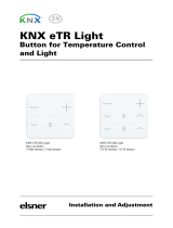
Figure 1. inBOX 24. Elements
Note: the above element diagram refers to inBOX 24. It is entirely analogous for inBOX
20, although the inputs are not available.
The main elements of the device are described next.
Test/Prog. Pushbutton (3): a short press on this button sets the device into
the programming mode, making the associated LED (2) light in red.
Note: if this button is held while plugging the device into the KNX bus, the
device will enter into safe mode. In such case, the LED will blink in red every
0.5 seconds.
Outputs (5): output ports for the insertion of the stripped cables of the
systems being controlled by the actuator (see section 2.3). Please secure the
1. Output status LED.
2. Prog./Test LED.
3. Prog./Test pushbutton.
4. Inputs.
5. Outputs.
6. Output control button.
7. KNX connector.
3
5
7
2
4
1
6

inBOX 24 / inBOX 20
http://www.zennio.com Technical Support: http://support.zennio.com
6
connection by means of the on-board screws.
Inputs (4): input ports for the insertion of the stripped cables of external
elements such as switches / motion detectors / temperature probes, etc. One
of the two cables of each element needs to be connected to one of the slots
labelled “1” to “4”, while the other cable should be connected to the slot
labelled as “C”. Note that all the external input devices share the “C” slot for
one of the two cables. Please secure the connection by means of the on-
board screws.
To get detailed information about the technical features of this device, as well as on the
installation and security procedures, please refer to the corresponding Datasheet,
bundled with the original package of the device and also available at www.zennio.com.
1.3 START-UP AND POWER LOSS
During the start-up of the device, the Test/Prog. LED will blink in blue colour for a few
seconds before the device is ready. External orders will not be executed during this
time, but afterwards.
Depending on the configuration, some specific actions will also be performed during
the start-up. For example, the integrator can set whether the output channels should
switch to a particular state and whether the device should send certain objects to the
bus after the power recovery. Please consult the next sections of this document for
further details.
On the other hand, when a bus power failure takes place, the device will interrupt any
pending actions, and will save its state so it can be recovered once the power supply is
restored. For safety reasons, the shutter channel will be stopped (i.e., the relays will
open) if a power loss takes place, while the individual outputs will switch to the specific
state configured in ETS (if any).

inBOX 24 / inBOX 20
http://www.zennio.com Technical Support: http://support.zennio.com
7
2 CONFIGURATION
2.1 GENERAL
After importing the corresponding database in ETS and adding the device into the
topology of the desired project, the configuration process begins by entering the
Parameters tab of the device.
ETS PARAMETERISATION
From the General screen it is possible to activate/deactivate all the required
functionality.
Figure 2. Default screen
Once activated, Inputs (only on inBOX 24), Outputs, Logic Functions,
Thermostats (only on inBOX 24), Master Light (only on inBOX 24), Scene
Temporisation and Manual Control bring additional tabs to the menu on the
left. These functions and their parameters will be explained in later sections of
this document.
The Manual Control function is enabled by default, and so is the
corresponding configuration tab.

inBOX 24 / inBOX 20
http://www.zennio.com Technical Support: http://support.zennio.com
8
Sending of Indication Objects (0 and 1) on Bus Voltage Recovery: this
parameter lets the integrator activate two new communication objects (“Reset
0” and “Reset 1”), which will be sent to the KNX bus with values “0” and “1”
respectively whenever the device begins operation (for example, after a bus
power failure). It is possible to parameterise a certain delay to this sending (0
to 255 seconds).
Figure 3. Sending of Indication objects on bus voltage recovery
Heartbeat (Periodical Alive Notification): this parameter lets the integrator
incorporate a one-bit object to the project (“[Heartbeat] Object to Send ‘1’”)
that will be sent periodically with value “1” to notify that the device is still
working (still alive).
Figure 4. Heartbeat (Periodical Alive Notification).
Note: The first sending after download or bus failure takes place with a delay
of up to 255 seconds, to prevent bus overload. The following sendings match
the period set.

inBOX 24 / inBOX 20
http://www.zennio.com Technical Support: http://support.zennio.com
9
2.2 INPUTS (ONLY inBOX 24)
inBOX 24 incorporates four analogue/digital inputs, each configurable as a:
Binary Input, for the connection of a pushbutton or a switch/sensor.
Temperature Probe, to connect a temperature sensor from Zennio or NTC
probes from third parties (the latter requires configuring their parameters in
ETS).
Motion Detector, for the connection of a motion detector (models ZN1IO-
DETEC-P and ZN1IO-DETEC-X from Zennio).
Important: older models of the Zennio motion detector (e.g., ZN1IO-DETEC
and ZN1IO-DETEC-N) will not work properly with inBOX 24.
ETS PARAMETERISATION
When Inputs has been activated in the General parameters screen, the following drop-
lists will be available for the selection of the specific functions required.
Figure 5. Inputs - Configuration
All inputs are disabled by default. Depending on the function selected for each input,
additional tabs will be included in the menu on the left.
2.2.1 BINARY INPUT
Please refer to the specific user manual “Binary Inputs”, available in the inBOX 24
¡product section, at the Zennio website (www.zennio.com).

inBOX 24 / inBOX 20
http://www.zennio.com Technical Support: http://support.zennio.com
10
2.2.2 TEMPERATURE PROBE
Please refer to the specific user manual “Temperature Probe”, available in the inBOX
24 product section, at the Zennio website (www.zennio.com).
2.2.3 MOTION DETECTOR
It is possible to connect motion detectors (models ZN1IO-DETEC-P and ZN1IO-
DETEC-X from Zennio) to the input ports of inBOX 24.
Please refer to the specific user manual “Motion Detector”, available in the inBOX 24
product section, at the Zennio website (www.zennio.com).
Notes:
The ZN1IO-DETEC-P motion detector is compatible with a variety of Zennio
devices. However, depending on the device it is actually being connected to,
the functionality may differ slightly. Therefore, please refer specifically to the
corresponding product section to obtain the aforementioned document.
Motion detectors with references ZN1IO-DETEC and ZN1IO-DETEC-N are
not compatible with inBOX 24 (may report inaccurate measurements if
connected to this device).
When connected to inBOX 24, the rear micro-switch of model ZN1IO-DETEC-
P should be set to position “Type B”.

inBOX 24 / inBOX 20
http://www.zennio.com Technical Support: http://support.zennio.com
11
2.3 OUTPUTS
The inBOX 24 / 20 actuators incorporate 2 relay outputs, each configurable as a:
Individual binary outputs, which allows an independent control of loads.
Shutter channel, which allow controlling the motion of shutters or blinds.
For detailed information about the functionality and the configuration of the related
parameters, please refer to the following specific manuals, all of them available in the
inBOX 24 / 20 product section at the Zennio homepage (www.zennio.com):
Individual outputs.
Shutter channels.
2.3.1 MANUAL CONTROL
inBOX 24 / 20 allows manually switching the state of its output relays through the
respective pushbuttons on the top of the device. A specific pushbutton is therefore
available per output.
Manual operation can be done in two different ways, named as Test On Mode (for
testing purposes during the configuration of the device) and Test Off Mode (for a
normal use, anytime). Whether both, only one, or none of these modes can be
accessed needs to be parameterised in ETS. Moreover, it is possible to enable a
specific binary object for locking and unlocking the manual control in runtime.
Note:
The Test Off mode will be active (unless it has been disabled by parameter)
after a download or a reset with no need of a specific activation – the
pushbuttons will respond to user presses from the start.
On the contrary, switching to the Test On mode (unless disabled by
parameter) needs to be done by long-pressing the Prog./Test button (for at
least three seconds), until the LED is no longer red and turns yellow. From
that moment, once the button is released, the LED light will remain green to
confirm that the device has switched from the Test Off mode to the Test On

inBOX 24 / inBOX 20
http://www.zennio.com Technical Support: http://support.zennio.com
12
mode. After that, an additional press will turn the LED yellow and then off,
once the button is released. This way, the device leaves the Test On mode.
Note that it will also leave this mode if a bus power failure takes place.
Test Off Mode
Under the Test Off Mode, the outputs can be controlled through both their
communication objects and the actual pushbuttons located on the top of the device.
When one of these buttons is pressed, the output will behave as if an order had been
received through the corresponding communication object, depending on whether the
output is configured as an individual output or as a shutter channel.
Individual output: a simple press (short or long) will make the output switch
its on-off state, which will be reported to the KNX bus through the
corresponding status object, if enabled.
Shutter Channel: when the button is pressed, the device will act over the
output according to the length of the button press and to the current state.
➢ A long press makes the shutter start moving (upwards or downwards,
depending on the button being pressed). The LED will light in green until
the end of the motion. If the button gets pressed being the shutter already
at the top or bottom positions, nothing will happen (the LED will not light).
➢ A short press will make the shutter drive stop (if in motion), as it normally
does when a step/stop order is received from the KNX bus. In case of not
being the shutter in motion, pressing the button does not cause any action,
unless slats/lamellas have been parameterized – in such case, a step
movement (up/down, depending on the button pressed) will take place.
The status objects will be sent to the bus when corresponding.
Disabled output: outputs disabled by parameter will not react to button
presses under the Test Off mode.
Regarding the lock, timer, alarm and scene functions, the device will behave under the
Test Off mode as usual. Button presses during this mode are entirely analogous to the
reception of the corresponding orders from the KNX bus.

inBOX 24 / inBOX 20
http://www.zennio.com Technical Support: http://support.zennio.com
13
Test On Mode
After entering the Test On mode, it will only be possible to control the outputs through
the on-board pushbuttons. Orders received through communication objects will be
ignored, with independence of the channel or the output they are addressed to.
Depending on whether the output has been parameterised as an individual output or as
part of a shutter channel, the reactions to the button presses will differ.
Individual output: short or long pressing the button will commute the on-off
state of the relay.
Shutter channel: pressing the button will make the shutter drive move
upward or downward (depending on the button) until the button is released
again, thus ignoring the position of the shutter and the parameterised times.
Note: after leaving the Test On mode, the status objects will recover the
values they had prior to entering Test On. As the device is never aware of the
actual position of the shutter (as the shutter drive does not provide any
feedback), these values may not show the real position. This can be solved
by performing a complete move-up or move-down order, or by calibrating the
shutter position in the Test On mode until it matches the status objects.
Disabled output: under the Test On mode, short and long presses will cause
the same effect for disabled outputs as for individual outputs (i.e., the relay
will switch its state).
The lock, timer, alarm and scene functions will not work while the device is under the
Test On mode. Status objects will not be sent to the bus, either.
Important: the device is delivered from factory with the outputs configured as disabled,
and with both manual modes (Test Off and Test On) enabled.
ETS PARAMETERISATION
The Manual Control is configured from the Configuration tab itself under Manual
Control.
The only two parameters are:

inBOX 24 / inBOX 20
http://www.zennio.com Technical Support: http://support.zennio.com
14
Figure 6. Manual control screen
Manual Control: options are “Disabled”, “Only Test Mode Off”, “Only Test
Mode On” and “Test Mode Off + Test On Mode” (default). Depending on the
selection, the device will permit using the manual control under the Test Off,
the Test On, or both modes. Note that, as stated before, using the Test Off
mode does not require any special action, while switching to the Test On
mode does require long-pressing the Prog./Test button.
Lock Manual Control: unless the above parameter has been “Disabled”, the
Lock Manual Control parameter provides an optional procedure for locking
the manual control in runtime. When this checkbox is enabled, object
“Manual Control Lock” turns visible, as well as two more parameters:
➢ Value: defines whether the manual control lock/unlock should take place
respectively upon the reception (through the aforementioned object) of
values “0” and “1”, or the opposite.
➢ Initialization: sets how the manual control should remain after the device
start-up (after an ETS download or a bus power failure): “Unlocked”,
“Locked” or “Last Value” (default; on the very first start-up, this will be
Unlocked).

inBOX 24 / inBOX 20
http://www.zennio.com Technical Support: http://support.zennio.com
15
2.4 LOGIC FUNCTIONS
This module makes it possible to perform numeric and binary operations to incoming
values received from the KNX bus, and to send the results through other
communication objects specifically enabled for this purpose.
inBOX 24 / 20 can implement up to 10 different and independent functions, each of
them entirely customisable and consisting in up to 4 consecutive operations each.
The execution of each function can depend on a configurable condition, which will be
evaluated every time the function is triggered through specific, parameterizable
communication objects. The result after executing the operations of the function can
also be evaluated according to certain conditions and afterwards sent (or not) to the
KNX bus, which can be done every time the function is executed, periodically or only
when the result differs from the last one.
Please refer to the specific “Logic Functions” user manual (available in the inBOX 24 /
20 product section at the Zennio homepage, www.zennio.com) for detailed information
about the functionality and the configuration of the related parameters.

inBOX 24 / inBOX 20
http://www.zennio.com Technical Support: http://support.zennio.com
16
2.5 THERMOSTATS (ONLY inBOX 24)
inBOX 24 implements four Zennio thermostats which can be enabled and configured
independently.
Please refer to the specific “Zennio Thermostat” user manual (available in the inBOX
24 product section at the Zennio homepage, www.zennio.com) for detailed information
about the functionality and the configuration of the related parameters.

inBOX 24 / inBOX 20
http://www.zennio.com Technical Support: http://support.zennio.com
17
2.6 MASTER LIGHT (ONLY inBOX 24)
The Master Light function brings the option to monitor the state of up to 12 light
sources –or any other functionally-similar element whose state is transmitted through a
binary object– and, depending on those states, perform a master order every time a
certain trigger signal (again, a binary value) is received through a specific object.
Such master order will consist in:
A general switch-off order, if at least one of the up to twelve status objects is
found to be on.
A courtesy switch-on order, if none of the up to twelve status objects is
found to be on.
Note that the above switch-off and switch-on orders are not necessarily a binary value
being sent to the bus – it is up to the integrator the decision of what to send to the KNX
bus in both cases: a shutter order, a thermostat setpoint or mode switch order, a
constant value, a scene… Only the trigger object and the twelve status objects are
required to be binary (on/off).
The most typical scenario for this Master Light control would be a hotel room with a
master pushbutton next to the door. When leaving the room, the guest will have the
possibility of pressing on the master pushbutton and make all the lamps turn off
together. Afterwards, back on the room and with all the lamps off, pressing on the
same master pushbutton will only make a particular lamp turn on (e.g., the closest lamp
to the door) – this is the courtesy switch-on.
ETS PARAMETERISATION
Once the Master Light function has been enabled, a specific tab will be included in the
menu on the left. This new parameter screen contains the following options:
Number of State Objects: defines the number of one-bit status objects
required. The minimum (and default) value is “1”, and the maximum is “12”.
These objects are called “[ML] Status Object n”.

inBOX 24 / inBOX 20
http://www.zennio.com Technical Support: http://support.zennio.com
18
Trigger Value: sets the value (“0”, “1” or “0/1”, being the latter the default
option) that will trigger, when received through “[ML] Trigger”, the master
action (the general switch-off or the courtesy switch-on).
General Switch-Off.
➢ Delay: defines a certain delay (once the trigger has been received) before
the execution of the general switch-off. The allowed range is 0 to 255
seconds.
➢ Binary Value: if checked, object “[ML] General Switch-off: Binary
Object” will be enabled, which will send one “0” whenever the general
switch-off takes off.
➢ Scaling: if checked, object “[ML] General Switch-off: Scaling” will be
enabled, which will send a percentage value (configurable in “Value”)
whenever the general switch-off takes off.
➢ Scene: if checked, object “[ML] General Switch-off: Scene” will be
enabled, which will send a scene run / save order (configurable in “Action”
and “Scene Number”) whenever the general switch-off takes off
➢ HVAC: if checked, object “[ML] General Switch-off: HVAC mode” will be
enabled, which will send an HVAC thermostat mode value (configurable in
“Value”, being the options “Auto”, “Comfort”, “Standby”, “Economy” and
“Building Protection”) whenever the general switch-off takes off
Note: the above options are not mutually exclusive; it is possible to send
values of different nature together.
Courtesy Switch-On:
The parameters available here are entirely analogous to those already
mentioned for General Switch-Off. However, in this case the names of the
objects start with “[ML] Courtesy Switch-On (…)”. On the other hand,
sending scene save orders is not possible for the courtesy switch-on (only
orders to play scenes are allowed).
Note: object “[ML] Courtesy Switch-On: Binary Object” sends the value “1”

inBOX 24 / inBOX 20
http://www.zennio.com Technical Support: http://support.zennio.com
19
(when the courtesy switch-on takes place), in contrast to object “[ML]
General Switch-Off: Binary Object”, which sends the value “0” (during the
general switch-off, as explained above).
Figure 7. Sending of Indication objects on bus voltage recovery

inBOX 24 / inBOX 20
http://www.zennio.com Technical Support: http://support.zennio.com
20
2.7 SCENE TEMPORISATION
The scene temporisation allows imposing delays over the scenes of the outputs.
These delays are defined in parameters, and can be applied to the execution of one or
more scenes that may have been configured.
Please bear in mind that, as multiple delayed scenes can be configured for each
individual output or shutter channel, in case of receiving an order to execute one of
them when a previous temporisation is still pending for that output or that channel, such
temporisation will be interrupted and only the delay and the action of the new scene will
be executed.
ETS PARAMETERISATION
Prior to setting the scene temporisation, it is necessary to have one or more scenes
configured in some of the outputs. When entering the Configuration window under
Scene Temporization, all configured scenes will be listed, together with a few
checkboxes to select which of them need to be temporised, as shown in Figure 8.
Figure 8. Scene temporisation
Enabling a certain scene number n brings a new tab with such name to the menu on
the left, from which it is possible to configure the temporisation of that scene for each of
the outputs where it has been configured.
/