Page is loading ...

KNX S4-B10 230 V
KNX S2-B6 230 V
KNX S1-B2 230 V
Multifunctional Actuators
Item numbers 70530 (KNX S4-B10 230 V), 70531 (KNX S2-B6 230 V), 70532 (KNX S1-B2 230 V)
EN
Installation and Ad justment


1 Content
Elsner Elektronik GmbH • Sohlengrund 16 • 75395 Ostelsheim • Germany
Actuator KNX S4 • from software version 4.00, ETS programme version 4.0
Status: 18.04.2017 • Technical changes and errors excepted.
1. Description ........................................................................................... 5
1.0.1. Scope of delivery .......................................................................................... 6
1.1. Technical Data .......................................................................................................... 6
2. Installation and start-up ....................................................................... 7
2.1. Installation notes ...................................................................................................... 7
2.2. Connection ................................................................................................................ 8
2.2.1. Device Design KNX S4-B10 230 V ............................................................... 9
2.2.2. Device Design KNX S2-B6 230 V ............................................................... 10
2.2.3. Device Design KNX S1-B2 230 V ............................................................... 11
2.2.4. Indication of operation mode with the Power LED .................................. 11
2.2.5. Status display by the channel LEDs .......................................................... 12
2.3. Notes on mounting and commissioning .............................................................. 12
2.4. Connection examples for binary inputs KNX S4-B10 and KNX S2-B6 .............. 13
2.4.1. Using the internal auxiliary voltage of the actuator ................................ 13
2.4.2. Using an external voltage .......................................................................... 13
2.5. Connecting example for binary inputs KNX S1-B2 230 V ................................... 14
2.5.1. Using the internal auxiliary voltage of the actuator ................................ 14
2.5.2. Using an external auxiliary voltage ........................................................... 14
3. Transfer protocol ............................................................................... 15
3.1. List of all communication objects ......................................................................... 15
4. Parameter setting .............................................................................. 39
4.1. General settings ..................................................................................................... 39
4.1.1. Local operation ........................................................................................... 39
4.2. Inputs ....................................................................................................................... 39
Input as bus button ..................................................................................... 40
4.3. Outputs .................................................................................................................... 44
4.3.1. Channel settings – drives ........................................................................... 45
4.3.1.1. Control (drives) ............................................................................ 47
Block – blocking objects ............................................................................. 51
Block – wind blocking ................................................................................. 52
Block – rain blocking ................................................................................... 53
Movement limits ......................................................................................... 54
4.3.1.2. Manual ........................................................................................... 54
4.3.1.3. Automation - external .................................................................. 55
4.3.1.4. Automatic - internal for shading (drives) .................................... 55
4.3.1.5. Automatic for windows (drives) .................................................. 60
4.3.1.6. Scenes (drives) ............................................................................. 64
4.3.1.7. Button inputs (drives) ................................................................... 64
Input as bus button ..................................................................................... 65
Input as actuator button ............................................................................. 65
Input as zero position sensor ..................................................................... 65
4.3.2. Channel settings – switch functions .......................................................... 65
4.3.2.1. Connection (switch functions) ..................................................... 66

2 Content
Elsner Elektronik GmbH • Sohlengrund 16 • 75395 Ostelsheim • Germany
Actuator KNX S4 • from software version 4.00, ETS programme version 4.0
Status: 18.04.2017 • Technical changes and errors excepted.
4.3.2.2. On/Off switch delays, time switching (switch functions) .......... 66
4.3.2.3. Blocking function (switch functions) ........................................... 67
4.3.2.4. Scenes (switch functions) ............................................................ 68
4.3.3. Button input (switch functions) ................................................................. 68
Input as bus button ..................................................................................... 68
Input as actuator button ............................................................................. 68
5. General part ....................................................................................... 70
5.1. Output channel with drive ..................................................................................... 70
5.1.1. Control modi for drive control ................................................................... 70
5.1.2. Connection option for zero position sensors ........................................... 71
5.2. Output channel with switch function .................................................................... 74
5.2.1. Correlation connection – time switch – block ........................................... 74

3 Clarification of signs
This manual is amended periodically and will be brought into line with new software
releases. The change status (software version and date) can be found in the contents footer.
If you have a device with a later software version, please check
www.elsner-elektronik.de in the menu area "Service" to find out whether a more up-to-
date version of the manual is available.
Clarification of signs used in this manual
Installation, inspection, commissioning and troubleshooting of the device
must only be carried out by a competent electrician.
Safety advice.
Safety advice for working on electrical connections, components,
etc.
DANGER!
... indicates an immediately hazardous situation which will lead to
death or severe injuries if it is not avoided.
WARNING!
... indicates a potentially hazardous situation which may lead to
death or severe injuries if it is not avoided.
CAUTION!
... indicates a potentially hazardous situation which may lead to
trivial or minor injuries if it is not avoided.
ATTENTION!
... indicates a situation which may lead to damage to property if it is
not avoided.
ETS In the ETS tables, the parameter default settings are marked by
underlining.

4 Clarification of signs

5 Description
Actuators KNX S4-B10, KNX S2-B6 and KNX S1-B2 230 V
Status: 18.04.2017 • Technical changes and errors excepted.
1. Description
The Actuators KNX S4-B10, KNX S2-B6 and KNX S1-B2 230 V with integrated
facade control have multifunctional outputs, pairs of buttons and monitoring LEDs.
Each of the multifunctional outputs can connect to either a drive with Up/Down control
(blinds, awnings, shutters, windows) or two switchable devices (On/Off for light and
ventilation). The connected drives and devices can be operated directly on the actuator
or via connected hand switches.
The automation can be specified externally or internally. Internally, there are numer-
ous options available for blocking, locking (e.g. master-slave) and priority definition
(e.g. manual-automatic). Scenes can be saved and called up via the bus (scene control
with 16 scenes per drive).
Binary inputs can be used either for direct operation (e.g. hand switches) or as bus
switches (or also for e.g. alarm notifications). The desired behaviour can be defined
precisely through selection of the response times in Standard, Comfort or Deadman
mode.
Functions:
• Multifunctional outputs each for a 230 V drive (shade, window) or for
connecting two switchable devices (light, fan)
KNX S4-B10: 4 outputs | KNX S2-B6: 2 outputs | KNX S1-B2: 1 output
• Keypad with button pairs and status LEDs
• Binary inputs for use as hand switches or as bus switches with variable
voltage (6...80 V DC, 6...240 V AC)
KNX S4-B10: 10 inputs | KNX S2-B6: 6 inputs | KNX S1-B2: 2 inputs
• Automatic runtime measurement of the drives for positioning (including
fault notification object)
• Position feedback (movement position, also slat position for blinds)
• Position storage (movement position) via 1-bit object (storage and call-up
e.g. via button)
•Control via internal or external automation
•Integrated shade control for each drive output (with slat tracking according
to sun position for blinds)
• Scene control for movement position with 16 scenes per drive (also slat
position for blinds)
• Mutual locking of two drives using zero position sensors prevents collisions
e.g. of shade and window (master–slave)
• Blocking objects and alarm notifications have different priorities, so safety
functions always take precedence (e.g. wind block)
• Manual or automatic priority setting via time or communication object
• 5 Safety objects for each channel
• Short time restriction (movement command blocked) and movement limitation
Configuration is made using the KNX software ETS 5. The product file can be down-
loaded from the Elsner Elektronik website on www.elsner-elektronik.de in the “Ser-
vice” menu.

6 Description
Actuators KNX S4-B10, KNX S2-B6 and KNX S1-B2 230 V
Status: 18.04.2017 • Technical changes and errors excepted.
1.0.1. Scope of delivery
•Actuator
1.1. Technical Data
KNX S4-B10 230 V (No. 70530):
KNX S2-B6 230 V (No. 70531):
Housing Plastic
Colour White
Assembly Series installation on mounting rails
Protection Category IP 20
Ambient temperature Operation -20...+70°C, Storage -55...+90°C
Ambient humidity max. 95% rH, avoid condensation
Operating voltage 230 V AC, 50 Hz
Current on Bus: 10 mA
Minimum current for runtime meas-
urement
AC effective 200 mA
Max. cable length Binary inputs 50 m
Data output KNX +/- Bus connector terminal
BCU type own microcontroller
PEI type 0
Goup addresses max. 1024
Assignments max. 1024
Dimensions approx. 107 x 88 x 60 (W × H × D, mm), 6 dividing units
Weight approx. 360 g
Power consumption Operation max. approx. 3.5 W
Standby max. approx. 0.6 W
Outputs 4 × outputs each with 2 connections for drive up/down or 2
devices, 230 V (PE/N/1/2),
total. max 10 A and max. 4 A per connection
Inputs 10 × binary inputs, universal voltage
(6...80V DC, 6...240 V AC)
Communication objects 567
Dimensions approx. 107 x 88 x 60 (W × H × D, mm), 6 dividing units
Weight ca. 360 g
Power consumption Operation max. approx, 3.5 W
Standby max. ca. 0.6 W
Outputs 2 × outputs
with 2 connections for drive Up/Down or 2 devices,
230 V (PE/N/1/2),
in total max. 10 A and max. 4 A per connection

7 Installation and start-up
Actuators KNX S4-B10, KNX S2-B6 and KNX S1-B2 230 V
Status: 18.04.2017 • Technical changes and errors excepted.
KNX S1-B2 230 V (No. 70532):
The products are compliant with the provisions of EU guidelines.
2. Installation and start-up
2.1. Installation notes
Installation, testing, operational start-up and troubleshooting should
only be performed by an electrician.
DANGER!
Risk to life from live voltage (mains voltage)!
There are unprotected live components within the device.
• VDE regulations and national regulations are to be followed.
• Ensure that all lines to be assembled are free of voltage and take
precautions against accidental switching on.
• Do not use the device if it is damaged.
• Take the device or system out of service and secure it against
unintentional use, if it can be assumed, that risk-free operation is no
longer guaranteed.
The device is only to be used for its intended purpose. Any improper modification or
failure to follow the operating instructions voids any and all warranty and guarantee
claims.
After unpacking the device, check it immediately for possible mechanical damage. If it
has been damaged in transport, inform the supplier immediately.
The device may only be used as a fixed-site installation; that means only when assem-
bled and after conclusion of all installation and operational start-up tasks and only in
the surroundings designated for it.
Inputs 6 × binary inputs, universal voltage
(6...80 V DC, 6...240 V AC)
Communication objects 295
Dimensions approx. 53 x 88 x 60 (W × H × D, mm), 3 dividing units
Weight approx. 170 g
Power consumption Operation max. approx, 1.2 W
Output 1 × Output with 2 connections for drive Up/Down or 2
devices, 230 V (PE/N/1/2),
in total max. 8 A and max. 4 A per connection
Inputs 2 × binary inputs, universal voltage
(6...80 V DC, 6...240 V AC)
Communication objects 141

8 Installation and start-up
Actuators KNX S4-B10, KNX S2-B6 and KNX S1-B2 230 V
Status: 18.04.2017 • Technical changes and errors excepted.
Elsner Elektronik is not liable for any changes in norms and standards which may occur
after publication of these operating instructions.
2.2. Connection
Follow the guidelines and standards for SELV electric circuits
while installing and cable laying of the KNX connection and
inputs.
Binary inputs:
The connections of the binary inputs including the auxiliary voltage output meet the
requirements for SELV electrical circuits. Mixed installation with non-SELV electrical
circuits or mixing of different auxiliary voltages is not permitted.

9 Installation and start-up
Actuators KNX S4-B10, KNX S2-B6 and KNX S1-B2 230 V
Status: 18.04.2017 • Technical changes and errors excepted.
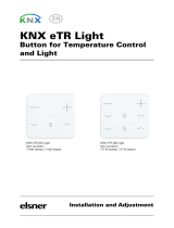
2.2.1. Device Design KNX S4-B10 230 V
The device is designed for series installation on mounting rails and occupies 6 width
units.
1) –/N (bridged internally with terminal No. 5). When an external auxiliary voltage
is used (6...80 V DC, 6...240 V AC), one of the –/N terminals is to be assigned with
– or N
2) Free contacts (bridged internally)
3) Programmer LED and programmer buttons (PRG)
4) Bus terminal slot (KNX +/-)
5) –/N (bridged internally with terminal No. 1).
6) Binary inputs 1-6 (1 and 2: two bridged connections)
7) Internal auxiliary voltage + 24 V DC. Only for binary inputs!
Do not assign any external voltage!
8) Binary inputs 7-10
9) Up/Down button pairs and LEDs channel A-D
10) Power LED, Indication of operation mode. See “Indication of operation mode
with the Power LED” on page 11.
11) Operating voltage input 230 V AC L/N/PE
12) Output A1 - A2: "Up"-"Down" or "Device1"-"Device2", max. 4 A
13) Output B1 - B2: "Up"-"Down" or "Device1"-"Device2", max. 4 A
14) Output C1 - C2: "Up"-"Down" or "Device1"-"Device2", max. 4 A
15) Output D1 - D2: "Up"-"Down" or "Device1"-"Device2", max. 4 A
16) All terminals L, N, PE of the lower connection strip are bridged internally with
„Main L, N, PE“.
3
4
5 7
9
10
1 2
6 8
11
12 13 14 15
16
Nº 12-15
together
max. 10 A

10 Installation and start-up
Actuators KNX S4-B10, KNX S2-B6 and KNX S1-B2 230 V
Status: 18.04.2017 • Technical changes and errors excepted.
2.2.2. Device Design KNX S2-B6 230 V
The device is designed for series installation on mounting rails and occupies 6 width
units.
1) –/N (bridged internally with terminal No. 5). When an external auxiliary voltage is used
(6...80 V DC, 6...240 V AC), one of the –/N terminals is to be assigned with – or N
2) Free contacts (bridged internally)
3) Programming LED and programming buttons (PRG)
4) Bus terminal slot (KNX +/-)
5) –/N (bridged internally with terminals No. 1)
6) Binary inputs 1-2 (two bridged connections)
7) Internal auxiliary voltage + 24 V DC. Only for binary inputs!
Do not assign any external voltage!
8) Binary inputs 3-6
9) Up/Down button pairs and LEDs channel A-B
10) Mains LED (Power), mode status display. See “Indication of operation mode with the
Power LED” on page 11.
11) Operating voltage input 230 V AC L/N/PE
12) Output A1 - A2: "Up"-"Down" respectively "Device1"-"Device2", max. 4 A
13) Output B1 - B2: "Up"-"Down" respectively "Device1"-"Device2", max. 4 A
14) All terminals L, N , PE of the lower connection strip are bridged internally with „main L,
N, PE“.
3
4
5 7
9
10
1 2
6 8
11
12 13 1414
No. 12-13
in total
max. 10 A

11 Installation and start-up
Actuators KNX S4-B10, KNX S2-B6 and KNX S1-B2 230 V
Status: 18.04.2017 • Technical changes and errors excepted.
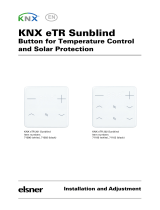
2.2.3. Device Design KNX S1-B2 230 V
The device is designed for series installation on mounting rails and occupies 3 width
units.
2.2.4. Indication of operation mode with the Power LED
Behaviour Colour
On Green Normal operation.
Bus connection/bus voltage available.
Flashes Green Normal operation.
No bus connection/bus voltage available.
On Orange Device starts up or is beeing programmed via the
ETS.
No automatic functions are executed.
Flashes Green (on)
Orange
(flashing)
Programming mode active.
1) Programming LED and programming but-
tons (PRG)
2) Bus terminal slot (KNX +/-)
3) Switch pair Up/Down and LEDs
4) Mains LED (Power), mode status display.
See “Indication of operation mode with
the Power LED” on page 11.
5) Operating voltage input 230 V AC L/N/PE
6) Output A1 - A2: "Up"-"Down" respectively
"Device1"-"Device2", max. 4 A
7) All terminals L, N, PE of the lower connec-
tion strip are bridged internally with „Main
L, N, PE“.
8) Binary inputs 1-2
9) Internal auxiliary voltage + 24 V DC. Only
for binary inputs! Do not assign any ex-
ternal voltage!
10) -/N for external auxiliary voltage
(6...80 V DC, 6...240 V AC)
2
9
4
6
7
10
1
3
5 8

12 Installation and start-up
Actuators KNX S4-B10, KNX S2-B6 and KNX S1-B2 230 V
Status: 18.04.2017 • Technical changes and errors excepted.
2.2.5. Status display by the channel LEDs
2.3. Notes on mounting and commissioning
Device must not be exposed to water (rain). This could result in the electronic being
damaged. A relative air humidity of 95% must not be exceeded. Avoid bedewing.
After the operating voltage has been applied, the device will enter an initialisation pha-
se lasting a few seconds. During this phase no information can be received or sent via
the bus.
For KNX devices with safety functions (e.g. wind or rain blocks), periodical monitoring
of the safety objects must be set up. The optimal ratio is 1:3 (example: if the weather
station sends a value every 5 minutes, the actuator must be configured for a monitor-
ing period of 15 minutes).
Behaviour LED
To top Drive in top end position/device on.
To bottom Drive in bottom end position/drive on.
Flashes slowly top Drive moves up.
Flashes slowly bottom Drive moves down.
Flashes
quickly
top Drive in top end position, blocking active.
Flashes
quickly
bottom Drive in bottom position, blocking active.
Flashes
quickly
both
simultaneously
Drive in intermediate position, blocking active.
Extend both Drive in intermediate position.
Flashes both alternately Automatic runtime determination error.
If the drive can be moved, drive it into the end
position by hand (drive in/drive out
completely or open/close) in order to restart
the runtime determination.
If the drive cannot be moved, check the
connections.
"Runlight"
above all LEDs
all channels Incorrect application version was loaded. Use
the version compatible with the device!

13 Installation and start-up
Actuators KNX S4-B10, KNX S2-B6 and KNX S1-B2 230 V
Status: 18.04.2017 • Technical changes and errors excepted.
2.4. Connection examples for binary inputs
KNX S4-B10 and KNX S2-B6
2.4.1. Using the internal auxiliary voltage of the actuator
2.4.2. Using an external voltage
Other binary inputs corresponding.
External auxiliary voltage
6...80 V DC resp. 6...240 V AC
B1 directly at the phase.
B3 via internally bridged voltage.
Other binary inputs corresponding.

14 Installation and start-up
Actuators KNX S4-B10, KNX S2-B6 and KNX S1-B2 230 V
Status: 18.04.2017 • Technical changes and errors excepted.
2.5. Connecting example for binary inputs
KNX S1-B2 230 V
2.5.1. Using the internal auxiliary voltage of the actuator
2.5.2. Using an external auxiliary voltage
According to additional binary inputs.
External auxiliary voltage
6...80 V DC or 6...240 V AC
B1 directly at the phase.
According to additional binary inputs.

15 Transfer protocol
Actuators KNX S4-B10, KNX S2-B6 and KNX S1-B2 230 V
Status: 18.04.2017 • Technical changes and errors excepted.
3. Transfer protocol
3.1. List of all communication objects
Abbreviations:
R Read
WWrite
C Communication
T Transfer
No. Name Function Flags Data Point Type Size
1 Software version Readable R-C- [217.1] DPT_Version 2 Bytes
Only KNX S4-B10 and KNX S2-B6
50 Input 1 long term Input /
output
RWCT [1.8] DPT_UpDown 1 Bit
51 Input 1 short term Output R-CT [1.8] DPT_UpDown 1 Bit
52 Input 1 switching Input /
output
RWCT [1.1] DPT_Switch 1 Bit
53 Input 1 dim relative Input /
output
RWCT [3.7]
DPT_Control_Dimm
ing
4 Bit
54 Input 1 encoder 8 bit Output R-CT [5] 5.xxx 1 Byte
55 Input 1 encoder
temperature
Output R-CT [9.1]
DPT_Value_Temp
2 Bytes
56 Input 1 encoder brightness Output R-CT [9.4]
DPT_Value_Lux
2 Bytes
57 Input 1 scene Output R-CT [18.1]
DPT_SceneControl
1 Byte
58 Input 1 blocking object Input RWC- [1.1] DPT_Switch 1 Bit
60 Input 2 long term Input /
output
RWCT [1.8] DPT_UpDown 1 Bit
61 Input 2 short term Output R-CT [1.8] DPT_UpDown 1 Bit
62 Input 2 switching Input /
output
RWCT [1.1] DPT_Switch 1 Bit
63 Input 2 dim relative Input /
output
RWCT [3.7]
DPT_Control_Dimm
ing
4 Bit
64 Input 2 encoder 8 bit Output R-CT [5] 5.xxx 1 Byte
65 Input 2 encoder
temperature
Output R-CT [9.1]
DPT_Value_Temp
2 Bytes
66 Input 2 encoder brightness Output R-CT [9.4]
DPT_Value_Lux
2 Bytes
67 Input 2 scene Output R-CT [18.1]
DPT_SceneControl
1 Byte

16 Transfer protocol
Actuators KNX S4-B10, KNX S2-B6 and KNX S1-B2 230 V
Status: 18.04.2017 • Technical changes and errors excepted.
68 Input 2 blocking object Input RWC- [1.1] DPT_Switch 1 Bit
All models
100 Channel A status automatic
or manual
Output R-CT [1] 1.xxx 1 Bit
101 Channel A manual long
term
Input RWC- [1.8] DPT_UpDown 1 Bit
102 Channel A manual short
term
Input RWC- [1.8] DPT_UpDown 1 Bit
103 Channel A manual
movement position
Input RWC- [5.1] DPT_Scaling 1 Byte
104 Channel A manual slat
position
Input RWC- [5.1] DPT_Scaling 1 Byte
105 Channel A automatic long
term
Input RWC- [1.8] DPT_UpDown 1 Bit
106 Channel A automatic short
term
Input RWC- [1.8] DPT_UpDown 1 Bit
107 Channel A automatic
movement position
Input RWC- [5.1] DPT_Scaling 1 Byte
108 Channel A automatic slat
position
Input RWC- [5.1] DPT_Scaling 1 Byte
109 Channel A switch from
manual to automatic
Input RWC- [1] 1.xxx 1 Bit
110 Channel A automatic
blocking object
Input RWC- [1.1] DPT_Switch 1 Bit
111 Channel A current
movement position
Output R-CT [5.1] DPT_Scaling 1 Byte
112 Channel A current slat
position
Output R-CT [5.1] DPT_Scaling 1 Byte
113 Channel A status object Output R-CT [1] 1.xxx 1 Bit
114 Channel A - Approach
position memory manually
Input RWC- [1.1] DPT_Switch 1 Bit
115 Channel A - Learn object 0
position memory manually
Input RWC- [1.1] DPT_Switch 1 Bit
116 Channel A - Learn object 1
position memory manually
Input RWC- [1.1] DPT_Switch 1 Bit
119 Channel A - Approach
position memory
automatically
Input RWC- [1.1] DPT_Switch 1 Bit
120 Channel A - Learn object 0
position memory
automatically
Input RWC- [1.1] DPT_Switch 1 Bit
121 Channel A - Learn object 1
position memory
automatically
Input RWC- [1.1] DPT_Switch 1 Bit
No. Name Function Flags Data Point Type Size

17 Transfer protocol
Actuators KNX S4-B10, KNX S2-B6 and KNX S1-B2 230 V
Status: 18.04.2017 • Technical changes and errors excepted.
124 Channel A call saving
scenes
Input RWC- [18.1]
DPT_SceneControl
1 Byte
125 Channel A outdoor
temperature
Blocking object
Input RWC- [1.1] DPT_Switch 1 Bit
126 Channel A outdoor
temperature blocking
measurement value
Input RWC- [9.1]
DPT_Value_Temp
2 Bytes
127 Channel A outdoor
temperature blocking status
Output R-CT [1.1] DPT_Switch 1 Bit
128 Channel A twilight object Input RWC- [1.1] DPT_Switch 1 Bit
129 Channel A twilight
measurement value
Input RWC- [9.4]
DPT_Value_Lux
2 Bytes
130 Channel A twilight status Output R-CT [1.1] DPT_Switch 1 Bit
131 Channel A time control Input RWC- [1.1] DPT_Switch 1 Bit
132 Channel A inside
temperature release object
Input RWC- [1.1] DPT_Switch 1 Bit
133 Channel A inside
temperature release
measurement value
Input RWC- [9.1]
DPT_Value_Temp
2 Bytes
134 Channel A inside
temperature release target
value
Input RWC- [9.1]
DPT_Value_Temp
2 Bytes
135 Channel A inside
temperature release status
Output R-CT [1.1] DPT_Switch 1 Bit
136 Channel A shading object Input RWC- [1.1] DPT_Switch 1 Bit
137 Channel A shading
brightness
Measurement value 1
Input RWC- [9.4]
DPT_Value_Lux
2 Bytes
138 Channel A shading
brightness
Measurement value 2
Input RWC- [9.4]
DPT_Value_Lux
2 Bytes
139 Channel A shading
brightness
Measurement value 3
Input RWC- [9.4]
DPT_Value_Lux
2 Bytes
140 Channel A shading
threshold value
Input /
output
RWCT [9.4]
DPT_Value_Lux
2 Bytes
141 Channel A shading
threshold value 1 = + | 0 = -
Input RWC- [1] 1.xxx 1 Bit
142 Channel A shading
threshold value +
Input RWC- [1] 1.xxx 1 Bit
143 Channel A shading
threshold value -
Input RWC- [1] 1.xxx 1 Bit
144 Channel A shading status Output R-CT [1.1] DPT_Switch 1 Bit
No. Name Function Flags Data Point Type Size

18 Transfer protocol
Actuators KNX S4-B10, KNX S2-B6 and KNX S1-B2 230 V
Status: 18.04.2017 • Technical changes and errors excepted.
145 Channel A shading position
Teaching object
Input RWC- [1] 1.xxx 1 Bit
146 Channel A azimuth Input RWC- [9] 9.xxx 2 Bytes
147 Channel A elevation Input RWC- [9] 9.xxx 2 Bytes
148 Channel A cold air supply
blocking object
Input RWC- [1.1] DPT_Switch 1 Bit
149 Channel A cold air supply
outside temperature
measurement value
Input RWC- [9.1]
DPT_Value_Temp
2 Bytes
150 Channel A cold supply air
blocking status
Output R-CT [1.1] DPT_Switch 1 Bit
151 Channel A forced
ventilation
Input RWC- [1.1] DPT_Switch 1 Bit
152 Channel A warm air supply
blocking object
Input RWC- [1.1] DPT_Switch 1 Bit
153 Channel A warm air supply
inside temperature
measurement value
Input RWC- [9.1]
DPT_Value_Temp
2 Bytes
154 Channel A warm air supply
outside temperature
measurement value
Input RWC- [9.1]
DPT_Value_Temp
2 Bytes
155 Channel A warm air supply
blocking target value
Input RWC- [9.1]
DPT_Value_Temp
2 Bytes
156 Channel A warm air supply
blocking status
Output R-CT [1.1] DPT_Switch 1 Bit
157 Channel A inside
temperature opening object
Input RWC- [1.1] DPT_Switch 1 Bit
158 Channel A inside
temperature opening
measurement value
Input RWC- [9.1]
DPT_Value_Temp
2 Bytes
159 Channel A inside
temperature opening target
value
Input RWC- [9.1]
DPT_Value_Temp
2 Bytes
160 Channel A inside
temperature opening
threshold value
Input /
output
RWCT [9.1]
DPT_Value_Temp
2 Bytes
161 Channel A inside
temperature opening
threshold value 1 = +
Input RWC- [1] 1.xxx 1 Bit
162 Channel A inside
temperature opening
threshold value +
Input RWC- [1] 1.xxx 1 Bit
163 Channel A inside
temperature opening
threshold value -
Input RWC- [1] 1.xxx 1 Bit
No. Name Function Flags Data Point Type Size
/