Page is loading ...

Item numbers 71381 (Cala KNX IL CH) and 71391 (Cala KNX IL CO2 CH)
EN
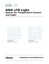
Cala KNX IL (CO2) CH
Indicator Light Green/Yellow/Red
Installation and Adjustment


1 Content
Elsner Elektronik GmbH • Sohlengrund 16 • 75395 Ostelsheim • Germany
Cala KNX IL CH light signal • from application 1.0
Version: 24.05.2023 • Technical changes and errors excepted.
1. Safety and operating instructions ....................................................... 3
2. Description ........................................................................................... 3
3. Commissioning .................................................................................... 4
3.1. Addressing the equipment ...................................................................................... 4
4. Transmission protocol ......................................................................... 5
4.1. List of all communication objects ........................................................................... 5
5. Setting of the parameters .................................................................. 11
5.1. Behaviour in case of power failure/restoration of power ................................... 11
5.2. General settings ..................................................................................................... 11
5.3. Light signal ............................................................................................................. 11
5.4. CO2 Measured value .............................................................................................. 16
5.5. CO2 threshold values ............................................................................................. 17
5.5.1. Threshold value 1, 2, 3, 4 ........................................................................... 17
5.6. CO2 PI controller ..................................................................................................... 20
5.7. Variable comparator .............................................................................................. 23
5.7.1. Control variable comparator 1/2 ................................................................ 23
5.8. Logic ........................................................................................................................ 24
5.8.1. AND logic 1-4 and OR logic outputs 1-4 ................................................... 25
5.8.2. AND logic connection inputs ..................................................................... 27
5.8.3. OR LOGIC connection inputs ..................................................................... 28

2 Clarification of signs
This manual is amended periodically and will be brought into line with new software
releases. The change status (software version and date) can be found in the contents footer.
If you have a device with a later software version, please check
www.elsner-elektronik.de in the menu area "Service" to find out whether a more up-to-
date version of the manual is available.
Clarification of signs used in this manual
Safety advice.
Safety advice for working on electrical connections, components,
etc.
DANGER! ... indicates an immediately hazardous situation which will lead to
death or severe injuries if it is not avoided.
WARNING! ... indicates a potentially hazardous situation which may lead to
death or severe injuries if it is not avoided.
CAUTION! ... indicates a potentially hazardous situation which may lead to
trivial or minor injuries if it is not avoided.
ATTENTION! ... indicates a situation which may lead to damage to property if it is
not avoided.
ETS In the ETS tables, the parameter default settings are marked by
underlining.

3 Safety and operating instructions
Cala KNX IL CH light signal • Version: 24.05.2023 • Technical changes and errors excepted.
1. Safety and operating instructions
Installation, testing, operational start-up and troubleshooting should
only be performed by an authorised electrician.
CAUTION!
Live voltage!
There are unprotected live components inside the device.
• Inspect the device for damage before installation. Only put undamaged devic-
es into operation.
• Comply with the locally applicable directives, regulations and provisions for
electrical installation.
• Immediately take the device or system out of service and secure it against un-
intentional switch-on if risk-free operation is no longer guaranteed.
Use the device exclusively for building automation and observe the operating instruc-
tions. Improper use, modifications to the device or failure to observe the operating in-
structions will invalidate any warranty or guarantee claims.
Operate the device only as a fixed-site installation, i.e. only in assembled condition and
after conclusion of all installation and operational start-up tasks, and only in the sur-
roundings designated for it.
Elsner Elektronik is not liable for any changes in norms and standards which may occur
after publication of these operating instructions.
For information on installation, maintenance, disposal, scope of deliv-
ery and technical data, please refer to the installation instructions.
2. Description
The LED area of the Cala KNX IL CH LED light signal can illuminate or flash in the
colours green, yellow or red. This allows states to be visualised for the KNX bus sys-
tem. E.g. threshold value violations, room occupancy or other status messages can be
linked to Cala KNX IL CH and the displayed colour changes if these threshold values
are exceeded / undercut.
States can be linked via AND logic gates and OR logic gates. An integrated actuating
variable comparator can compare and issue values that have been received via com-
munication objects.
With the Cala KNX IL CO2 CH model, the measured value of the integrated CO2 sen-
sor can be visualised via the illuminated area.
Via the bus, Cala KNX IL CO2 CH can receive an external CO2 value and process it
with its own data to form an overall value (mixed value, e.g. room average). The CO2
measured value can be used for the control of limit-dependent switch outputs.
A PI controller regulates ventilation according to CO2 concentration.

4 Commissioning
Cala KNX IL CH light signal • Version: 24.05.2023 • Technical changes and errors excepted.
Function of all models:
•Traffic-light function for visualising states (e. g. limit value violations, room
occupation of status reports)
• Display (permanent or flashing) of one of the colours Green, Yellow or Red
•4 AND and 4 OR logic gates each with 4 inputs. All switching events as well
as 16 logic inputs (in the form of communications objects) can be used as
inputs for the logic gates. The output from each gate can be configured
optionally as 1-bit or 2 x 8-bit
•2 control variable comparators to output minimum, maximum or average
values. 5 inputs each for values received via communication objects
Cala KNX IL CO2 CH (No. 71391) functions:
• Measuring the CO2-concentration in the air each time with mixed value
calculation. The share of internal measured value and external value can be
set as a percentage
•Use of the CO2-concentration for the traffic-light function
•Threshold values can be adjusted per parameter or via communication
objects
•PI controller for two-stage ventilation according to CO2-concentration
3. Commissioning
Configuration is made using the KNX software as of ETS 5. The product file can be
downloaded from the ETS online catalogue and the Elsner Elektronik website on
www.elsner-elektronik.de.
After the bus voltage has been applied, the device will enter an initialisation phase last-
ing approx. 5 seconds. During this phase no information can be received or sent via the
bus.
3.1. Addressing the equipment
The equipment is delivered with the bus address 15.15.255. Another address can be
programmed using the ETS.
The programming button can be reached through the opening on the rear of the hous-
ing; it is recessed. Use a thin object to reach the button, e.g. a 1.5 mm² wire.

5 Transmission protocol
Cala KNX IL CH light signal • Status: 24.05.2023 • Technical changes reserved. Errors reserved.
4. Transmission protocol
Units:
CO2 content in ppm
Variables in %
4.1. List of all communication objects
Abbreviations Flags:
C Communication
R Read
WWrite
T Transmit
UUpdate
No Text Function Flags DPT type Size
0 Output soft-
ware version
Software version R-CT- [217.1] DPT_Ver-
sion
2 Bytes
11 Input light sig-
nal
Light signal On/Off RWC-- [1.1] DPT_Switch 1 Bit
12 Input light sig-
nal
Light signal brightness RWC-- [5.1] DPT_Scal-
ing
1 Byte
16 Input light sig-
nal
Light signal colour red On/Off -WC-- [1.1] DPT_Switch 1 Bit
17 Input light sig-
nal
Light signal colour yellow On/
Off
-WC-- [1.1] DPT_Switch 1 Bit
18 Input light sig-
nal
Light signal colour green On/Off -WC-- [1.1] DPT_Switch 1 Bit
19 Input light sig-
nal
“Light signal colour selection 1
byte (0=Off, 1=Green, 2=Yellow,
3=Red)”
-WC-- [5.10] DPT_Val-
ue_1_Ucount
1 Byte
24 Input / output
light signal
Light signal measured value for
GW
-WC-- [9.7] DPT_Val-
ue_Humidity
2 Bytes
25 Input / output
light signal
Light signal GW green/yellow RWCT
-
[9.7] DPT_Val-
ue_Humidity
2 Bytes
26 Input / output
light signal
Light signal GW yellow/red RWCT
-
[9.7] DPT_Val-
ue_Humidity
2 Bytes
27 Input / output
light signal
Light signal GW hysteresis RWCT
-
[9.7] DPT_Val-
ue_Humidity
2 Bytes
35 Output light
signal
Light signal status colour red
On/Off
R-CT- [1.1] DPT_Switch 1 Bit
36 Output light
signal
Light signal status colour yellow
On/Off
R-CT- [1.1] DPT_Switch 1 Bit
37 Output light
signal
Light signal status colour green
On/Off
R-CT- [1.1] DPT_Switch 1 Bit

6 Transmission protocol
Cala KNX IL CH light signal • Status: 24.05.2023 • Technical changes reserved. Errors reserved.
39 Output light
signal
Light signal status RGB red R-CT- [5.10] DPT_Val-
ue_1_Ucount
1 Byte
40 Output light
signal
Light signal status RGB green R-CT- [5.10] DPT_Val-
ue_1_Ucount
1 Byte
41 Output light
signal
Light signal status RGB blue R-CT- [5.10] DPT_Val-
ue_1_Ucount
1 Byte
42 Output light
signal
Light signal status colour RGB R-CT- [232.600]
DPT_Col-
our_RGB
3 Bytes
44 Indicator Light “Light signal status byte (0=Off,
1=Green, 2=Yellow, 3=Red)”
R-CT- [5.10] DPT_Val-
ue_1_Ucount
1 Byte
Only with Cala KNX IL CO2 CH
70 Output CO2
sensor
CO2 malfunction (0=OK | 1=NOT
OK)
R-CT- [1.1] DPT_Switch 1 Bit
71 Input CO2
measured
value
Outside CO2 reading -WCT- [9.8] DPT_Val-
ue_AirQuality
2 Bytes
72 Output CO2
measured
value
CO2 measured value internal R-CT- [9.8] DPT_Val-
ue_AirQuality
2 Bytes
73 Output CO2
measured
value
CO2 measured value total R-CT- [9.8] DPT_Val-
ue_AirQuality
2 Bytes
74 Input CO2
measured
value
CO2 measured value require-
ment max.
-WC-- [1.17] DPT_Trig-
ger
1 Bit
75 Output CO2
measured
value
Maximum CO2 measured value R-CT- [9.8] DPT_Val-
ue_AirQuality
2 Bytes
76 Input CO2
measured
value
CO2 measured value reset max. -WC-- [1.17] DPT_Trig-
ger
1 Bit
77 Input / Output
CO2-GW 1
CO2-GW 1 absolute value RWCT
-
[9.8] DPT_Val-
ue_AirQuality
2 Bytes
78 Input CO2-GW
1
CO2-GW 1 change (1: + | 0: -) -WC-- [1.1] DPT_Switch 1 Bit
79 Input CO2-GW
1
CO2-GW 1 switch delay from 0
to 1
RWC-- [7.5] DPT_Time-
PeriodSec
2 Bytes
80 Input CO2-GW
1
CO2-GW 1 switch delay from 1
to 0
RWC-- [7.5] DPT_Time-
PeriodSec
2 Bytes
81 Output CO2-
GW 1
CO2-GW 1 switch output R-CT- [1.1] DPT_Switch 1 Bit
82 Input CO2-GW
1
CO2-GW 1 switch output lock -WC-- [1.1] DPT_Switch 1 Bit
No Text Function Flags DPT type Size

7 Transmission protocol
Cala KNX IL CH light signal • Status: 24.05.2023 • Technical changes reserved. Errors reserved.
83 Input / Output
CO2-GW 2
CO2-GW 2 absolute value RWCT
-
[9.8] DPT_Val-
ue_AirQuality
2 Bytes
84 Input CO2-GW
2
CO2-GW 2 change (1: + | 0: -) -WC-- [1.1] DPT_Switch 1 Bit
85 Input CO2-GW
2
CO2-GW 2 switch delay from 0
to 1
RWC-- [7.5] DPT_Time-
PeriodSec
2 Bytes
86 Input CO2-GW
2
CO2-GW 2 switch delay from 1
to 0
RWC-- [7.5] DPT_Time-
PeriodSec
2 Bytes
87 Output CO2-
GW 2
CO2-GW 2 switch output R-CT- [1.1] DPT_Switch 1 Bit
88 Input CO2-GW
2
CO2-GW 2 switch output lock -WC-- [1.1] DPT_Switch 1 Bit
89 Input / Output
CO2-GW 3
CO2-GW 3 absolute value RWCT
-
[9.8] DPT_Val-
ue_AirQuality
2 Bytes
90 Input CO2-GW
3
CO2-GW 3 change (1: + | 0: -) -WC-- [1.1] DPT_Switch 1 Bit
91 Input CO2-GW
3
CO2-GW 3 switch delay from 0
to 1
RWC-- [7.5] DPT_Time-
PeriodSec
2 Bytes
92 Input CO2-GW
3
CO2-GW 3 switch delay from 1
to 0
RWC-- [7.5] DPT_Time-
PeriodSec
2 Bytes
93 Output CO2-
GW 3
CO2-GW 3 switch output R-CT- [1.1] DPT_Switch 1 Bit
94 Input CO2-GW
3
CO2-GW 3 switch output lock -WC-- [1.1] DPT_Switch 1 Bit
95 Input / Output
CO2-GW 4
CO2-GW 4 absolute value RWCT
-
[9.8] DPT_Val-
ue_AirQuality
2 Bytes
96 Input CO2-GW
4
CO2-GW 4 change (1: + | 0: -) -WC-- [1.1] DPT_Switch 1 Bit
97 Input CO2-GW
4
CO2-GW 4 switch delay from 0
to 1
RWC-- [7.5] DPT_Time-
PeriodSec
2 Bytes
98 Input CO2-GW
4
CO2-GW 4 switch delay from 1
to 0
RWC-- [7.5] DPT_Time-
PeriodSec
2 Bytes
99 Output CO2-
GW 4
CO2-GW 4 switch output R-CT- [1.1] DPT_Switch 1 Bit
100 Input CO2-GW
4
CO2-GW 4 switch output lock -WC-- [1.1] DPT_Switch 1 Bit
101 Input CO2 con-
troller
CO2 controller: Block (1: block) -WC-- [1.2] DPT_Bool 1 Bit
102 Input / Output
CO2 controller
CO2 controller setpoint RWCT
-
[9.8] DPT_Val-
ue_AirQuality
2 Bytes
103 Input CO2 con-
troller
CO2 controller setpoint (1:+ | 0:-) -WC-- [1.2] DPT_Bool 1 Bit
104 Output CO2
controller
CO2 controller setpoint ventila-
tion
R-CT- [5.1] DPT_Scal-
ing
1 Byte
No Text Function Flags DPT type Size

8 Transmission protocol
Cala KNX IL CH light signal • Status: 24.05.2023 • Technical changes reserved. Errors reserved.
105 Output CO2
controller
CO2 controller setpoint ventila-
tion level 2
R-CT- [5.1] DPT_Scal-
ing
1 Byte
106 Output CO2
controller
CO2 controller status ventila-
tion (1:ON | 0:OFF)
R-CT- [1.1] DPT_Switch 1 Bit
107 Output CO2
controller
CO2 controller status ventila-
tion 2 (1:ON | 0:OFF)
R-CT- [1.1] DPT_Switch 1 Bit
For all models
121 Input actuat-
ing variable
comparator
Actuating variable comparator
1: Input 1
-WC-- [5.1] DPT_Scal-
ing
1 Byte
122 Input actuat-
ing variable
comparator
Actuating variable comparator
1: Input 2
-WC-- [5.1] DPT_Scal-
ing
1 Byte
123 Input actuat-
ing variable
comparator
Actuating variable comparator
1: Input 3
-WC-- [5.1] DPT_Scal-
ing
1 Byte
124 Input actuat-
ing variable
comparator
Actuating variable comparator
1: Input 4
-WC-- [5.1] DPT_Scal-
ing
1 Byte
125 Input actuat-
ing variable
comparator
Actuating variable comparator
1: Input 5
-WC-- [5.1] DPT_Scal-
ing
1 Byte
126 Output actuat-
ing variable
comparator
Actuating variable comparator
1: Output
R-CT- [5.1] DPT_Scal-
ing
1 Byte
127 Input actuat-
ing variable
comparator
Actuating variable comparator
1: Block (1: block)
-WC-- [1.2] DPT_Bool 1 Bit
128 Input actuat-
ing variable
comparator
Actuating variable comparator
2: Input 1
-WC-- [5.1] DPT_Scal-
ing
1 Byte
129 Input actuat-
ing variable
comparator
Actuating variable comparator
2: Input 2
-WC-- [5.1] DPT_Scal-
ing
1 Byte
130 Input actuat-
ing variable
comparator
Actuating variable comparator
2: Input 3
-WC-- [5.1] DPT_Scal-
ing
1 Byte
131 Input actuat-
ing variable
comparator
Actuating variable comparator
2: Input 4
-WC-- [5.1] DPT_Scal-
ing
1 Byte
132 Input actuat-
ing variable
comparator
Actuating variable comparator
2: Input 5
-WC-- [5.1] DPT_Scal-
ing
1 Byte
No Text Function Flags DPT type Size

9 Transmission protocol
Cala KNX IL CH light signal • Status: 24.05.2023 • Technical changes reserved. Errors reserved.
133 Output actuat-
ing variable
comparator
Actuating variable comparator
2: Output
R-CT- [5.1] DPT_Scal-
ing
1 Byte
134 Input actuat-
ing variable
comparator
Actuating variable comparator
2: Block (1: block)
-WC-- [1.2] DPT_Bool 1 Bit
141 Input logic Logic input 1 -WC-- [1.2] DPT_Bool 1 Bit
142 Input logic Logic input 2 -WC-- [1.2] DPT_Bool 1 Bit
143 Input logic Logic input 3 -WC-- [1.2] DPT_Bool 1 Bit
144 Input logic Logic input 4 -WC-- [1.2] DPT_Bool 1 Bit
145 Input logic Logic input 5 -WC-- [1.2] DPT_Bool 1 Bit
146 Input logic Logic input 6 -WC-- [1.2] DPT_Bool 1 Bit
147 Input logic Logic input 7 -WC-- [1.2] DPT_Bool 1 Bit
148 Input logic Logic input 8 -WC-- [1.2] DPT_Bool 1 Bit
149 Input logic Logic input 9 -WC-- [1.2] DPT_Bool 1 Bit
150 Input logic Logic input 10 -WC-- [1.2] DPT_Bool 1 Bit
151 Input logic Logic input 11 -WC-- [1.2] DPT_Bool 1 Bit
152 Input logic Logic input 12 -WC-- [1.2] DPT_Bool 1 Bit
153 Input logic Logic input 13 -WC-- [1.2] DPT_Bool 1 Bit
154 Input logic Logic input 14 -WC-- [1.2] DPT_Bool 1 Bit
155 Input logic Logic input 15 -WC-- [1.2] DPT_Bool 1 Bit
156 Input logic Logic input 16 -WC-- [1.2] DPT_Bool 1 Bit
157 Output AND
Logic
AND logic 1: 1-bit switch output R-CT- [1.2] DPT_Bool 1 Bit
158 Output AND
Logic
AND logic 1: 8 bit output A R-CT- depending on
setting
1 Byte
159 Output AND
Logic
AND logic 1: 8 bit output B R-CT- depending on
setting
1 Byte
160 Input AND
Logic
AND logic 1: Block -WC-- [1.1] DPT_Switch 1 Bit
161 Output AND
Logic
AND logic 2: 1 bit switching out-
put
R-CT- [1.2] DPT_Bool 1 Bit
162 Output AND
Logic
AND logic 2: 8 bit output A R-CT- depending on
setting
1 Byte
163 Output AND
Logic
AND logic 2: 8 bit output B R-CT- depending on
setting
1 Byte
164 Input AND
Logic
AND logic 2: Block -WC-- [1.1] DPT_Switch 1 Bit
165 Output AND
Logic
AND logic 3: 1 bit switching out-
put
R-CT- [1.2] DPT_Bool 1 Bit
166 Output AND
Logic
AND logic 3: 8 bit output A R-CT- depending on
setting
1 Byte
No Text Function Flags DPT type Size

10 Transmission protocol
Cala KNX IL CH light signal • Status: 24.05.2023 • Technical changes reserved. Errors reserved.
167 Output AND
Logic
AND logic 3: 8 bit output B R-CT- depending on
setting
1 Byte
168 Input AND
Logic
AND logic 3: Block -WC-- [1.1] DPT_Switch 1 Bit
169 Output AND
Logic
AND logic 4: 1 bit switching out-
put
R-CT- [1.2] DPT_Bool 1 Bit
170 Output AND
Logic
AND logic 4: 8 bit output A R-CT- depending on
setting
1 Byte
171 Output AND
Logic
AND logic 4: 8 bit output B R-CT- depending on
setting
1 Byte
172 Input AND
Logic
AND logic 4: Block -WC-- [1.1] DPT_Switch 1 Bit
173 Output OR
Logic
OR logic 1: 1 bit switching out-
put
R-CT- [1.2] DPT_Bool 1 Bit
174 Output OR
Logic
OR logic 1: 8 bit output A R-CT- depending on
setting
1 Byte
175 Output OR
Logic
OR logic 1: 8 bit output B R-CT- depending on
setting
1 Byte
176 Input OR Logic OR logic 1: Block -WC-- [1.1] DPT_Switch 1 Bit
177 Output OR
Logic
OR logic 2: 1 bit switching out-
put
R-CT- [1.2] DPT_Bool 1 Bit
178 Output OR
Logic
OR logic 2: 8 bit output A R-CT- depending on
setting
1 Byte
179 Output OR
Logic
OR logic 2: 8 bit output B R-CT- depending on
setting
1 Byte
180 Input OR Logic OR logic 2: Block -WC-- [1.1] DPT_Switch 1 Bit
181 Output OR
Logic
OR logic 3: 1 bit switching out-
put
R-CT- [1.2] DPT_Bool 1 Bit
182 Output OR
Logic
OR logic 3: 8 bit output A R-CT- depending on
setting
1 Byte
183 Output OR
Logic
OR logic 3: 8 bit output B R-CT- depending on
setting
1 Byte
184 Input OR Logic OR logic 3: Block -WC-- [1.1] DPT_Switch 1 Bit
185 Output OR
Logic
OR logic 4: 1 bit switching out-
put
R-CT- [1.2] DPT_Bool 1 Bit
186 Output OR
Logic
OR logic 4: 8 bit output A R-CT- depending on
setting
1 Byte
187 Output OR
Logic
OR logic 4: 8 bit output B R-CT- depending on
setting
1 Byte
188 Input OR Logic OR logic 4: Block -WC-- [1.1] DPT_Switch 1 Bit
No Text Function Flags DPT type Size

11 Setting of the parameters
Cala KNX IL CH light signal • Status: 24.05.2023 • Technical changes reserved. Errors reserved.
5. Setting of the parameters
5.1. Behaviour in case of power failure/restoration
of power
Behaviour following a failure of the bus power supply:
The device sends nothing.
Behaviour on bus restoration of power and following programming or reset:
The device sends all outputs according to their send behaviour set in the parameters
with the delay that was established in the "General settings" parameter block.
5.2. General settings
First set the send delay after bus voltage recovery and programming.
This delay should be coordinated with the entire KNX-system, i.e. in a KNX system with
many participants, care should be taken that the bus is not overloaded after a KNX-bus
reset. The messages sent to the individual participants should be staggered.
The bus load is limited with the aid of the maximum message rate. Many messages per
second put a strain on the bus but ensure faster data transmission.
5.3. Light signal
Conditions for the KNX bus system can be visualised by the light signal.
Choose whether the light signal should be on or off after a reset.
Set the brightness of the light signal after a reset.
Transmission delay after reset/bus restora-
tion
5 s • ... • 300 s
Maximum telegram rate • 1 message per second
• ...
• 10 messages per second
• ...
• 50 messages per second
Light signal
valid until the first communication
Off • On
Brightness
valid until the first communication
0…100 %

12 Setting of the parameters
Cala KNX IL CH light signal • Status: 24.05.2023 • Technical changes reserved. Errors reserved.
Set how the signal colour is determined.
Status information is received by the 3 one-bit objects. For example, a window contact
can control the colour change this way.
A scenario number is received by the scenario object. So, for example, the “meeting”
scenario created can switch the door signal of a room to red.
An integral percent value is received by the percent object. The threshold value entered
in ETS controls the colour change. For example, the colour can change when the tank
fill level falls short.
A value is received by the two-byte object. Thus, for example, an external CO2 meas-
ured value can be visualised.
In Cala KNX IL CO2 CH, the value measured by the integrated CO2 sensor value (CO2
total measurement) can be used for the signal colour. This then lights up correspond-
ing to the current measured value and the set threshold values.
Depending on the selection, other settings appear hereafter.
3 x one-bit object:
1 x scenario object:
Set the scenario numbers.
In case of pre-set values, Cala KNX IL CH does not light up at all for scenario number
1, lights up green for scenario number 2, yellow for 3 and red for 4.
Signal colour is determined by • 3 x one-bit object
• 1 x scenario object
• 1 x percent object with limit value
• 1 x two-byte floating point object
with limit value
• CO2 total measured value (only for ver-
sion Cala KNX IL CO2 CH with integrated
sensor)
Signal colour is determined by 3 x one-bit object
Priority 1: Red
Priority 2: Yellow
Priority 3: Green
Note: No colour is active before the first
object receipt after reset
Signal colour is determined by 1 x scenario object
Scenario number for off 1...64
Scenario number for green 1...64; 2
Scenario number for yellow 1...64; 3
Scenario number for red 1...64; 4
Note:
If several of the same scenario numbers are
issued, the following priority is applicable:
Red, yellow, green, off
No colour is active before the first object
receipt after reset

13 Setting of the parameters
Cala KNX IL CH light signal • Status: 24.05.2023 • Technical changes reserved. Errors reserved.
1 x percent object with limit value:
Set whether the limit values received via object and the switching distance (hysteresis)
should be retained in reset and programming.
Set the limit value for colour change from green to yellow. You can specify the thresh-
old value via communication object no. 25 (light signal TV green/yellow) also.
Set the limit value for colour change from yellow to red. You can specify the threshold
value via communication object no. 26 (light signal TV yellow/red) also.
Set the switching distance (hysteresis) for colour change from red to yellow, and yel-
low to green. It specifies how low the value must be below the threshold value before
the colour switches. You can specify the switching distance (hysteresis) via communi-
cation object no. 27 (light signal TV of switching distance (hysteresis)) also.
1 x two-byte floating point object with limit value:
Set whether the limit values received via object and the switching distance (hysteresis)
should be retained in reset and programming.
Set the limit value for colour change from green to yellow. You can specify the thresh-
old value via communication object no. 25 (light signal TV green/yellow) also.
Signal colour is determined by 1 x percent object with limit value
Note: No colour is active before the first
object receipt after reset
The limit values received via object and the
switching distance (hysteresis) should
• not be retained
• after reset
• after reset and programming
.
Start limit value for change from green to
yellow
0…100 %; 33 %
Start limit value for change from green to
red
0…100 %; 66 %
Start switching distance (hysteresis) for
falling values
0…50 %; 5 %
Signal colour is determined by 1 x two-byte floating point object
with limit value
Note: No colour is active before the first
object receipt after reset
The limit values received via object and the
switching distance (hysteresis) should
• not be retained
• after reset
• after reset and programming
.
Start limit value for change from green to
yellow [x 0.1]
-6700000…6700000; 200

14 Setting of the parameters
Cala KNX IL CH light signal • Status: 24.05.2023 • Technical changes reserved. Errors reserved.
Set the limit value for colour change from yellow to red. You can specify the threshold
value via communication object no. 26 (light signal TV yellow/red) also.
Set the switching distance (hysteresis) for colour change from red to yellow, and yel-
low to green. It specifies how low the received value must be below the threshold value
before the colour switches. You can specify the switching distance (hysteresis) via
communication object no. 27 (light signal TV of switching distance (hysteresis)) also.
1 x CO2 total measured value (only for Cala KNX IL CO2 CH):
Set when the limit values received via object and the switching distance (hysteresis)
should be retained.
Set the limit value for colour change from green to yellow. You can specify the thresh-
old value via communication object no. 25 (light signal TV green/yellow) also.
Set the limit value for colour change from yellow to red. You can specify the threshold
value via communication object no. 26 (light signal TV yellow/red) also.
Set the switching distance (hysteresis) for colour change from red to yellow, and yel-
low to green. It specifies how low the received value must be below the threshold value
before the colour switches. You can specify the switching distance (hysteresis) via
communication object no. 27 (light signal TV of switching distance (hysteresis)) also.
Set the display behaviour of the red light signal.
Start limit value for change from yellow to
red [x 0.1]
-6700000…6700000; 250
Start switching distance (hysteresis) for
falling values [x 0.1]
0…3000000; 20
Signal colour is determined by 1 x CO2 total measured value
The limit values received via object and the
switching distance (hysteresis) should
• not be retained
• after reset
• after reset and programming
.
Start limit value for change from green to
yellow [ppm]
700…2000; 1000
Start limit value for change from green to
red [ppm]
800…3000; 1400
Start switching distance (hysteresis) for
falling values [ppm]
50…300; 200
If the signal colour Red is active, the light
signal should be
• be permanently On
• be permanently Off
• flashing

15 Setting of the parameters
Cala KNX IL CH light signal • Status: 24.05.2023 • Technical changes reserved. Errors reserved.
Set the flash cycle.
Set the display behaviour of the yellow light signal.
Set the flash cycle.
Set the display behaviour of the green light signal.
Set the flash cycle.
Use status objects to forward the colour display to other KNX participants. Then set the
send behaviour.
Set the send cycle mode.
Select the colour using the colour picker or set the respective status colour as a hex
code, which is sent to the KNX bus. This code is used for colour representation by
screens and LEDs and can be represented by corresponding KNX participants.
Flash cycle (in 0.1 s)
(When signal colour flashes)
2...20; 5
If the signal colour Yellow is active, the
light signal should be
• be permanently On
• be permanently Off
• flashing
Flash cycle (in 0.1 s)
(When signal colour flashes)
2...20; 5
If the signal colour Green is active, the light
signal should be
• be permanently On
• be permanently Off
• flashing
Flash cycle (in 0.1 s)
(When signal colour flashes)
2...20; 5
Send status objects for signal colour • do not retain
• upon changes
• upon change and periodically
Send cycle
(if sent periodically)
5 s • 10 s • 30 s • ... • 2 h
Value for ‘Status colour RGB’ object in sta-
tus = green
#000000 ...#FFFFFF; #00FF00
Value for ‘Status colour RGB’ object in sta-
tus = yellow
#000000 ...#FFFFFF; #FFFF00
Value for ‘Status colour RGB’ object in sta-
tus = red
#000000 ...#FFFFFF; #FF0000
Value for ‘Status colour RGB’ object in sta-
tus = Off (only for 3 x one-bit object and 1 x
scenario object)
#000000 ...#FFFFFF

16 Setting of the parameters
Cala KNX IL CH light signal • Status: 24.05.2023 • Technical changes reserved. Errors reserved.
5.4. CO2 Measured value
Only for Cala KNX IL CO2 CH version with integrated sensor.
Select whether to send an interference object if the sensor is defective. The fault ob-
ject can be used by other bus participants for monitoring.
Always use the automatic sensor calibration.
The CO2 sensor uses the latest 7 CO2 minimum values for automatic sensor calibration.
These 7 minimum values must have a gap of at least 18 hours from each other and lie
within the range of 400 to 450 ppm (fresh air).
The CO2 value output can be corrected by an offset value, if needed.
The unit can calculate a mixed value from its own reading and an external value, e.g.,
room average if two CO2 sensors are attached in one room. Set the mixed value calcu-
lation if desired. If an external portion is used, all the following settings (threshold val-
ues, etc.) are related to the overall measured value!
Set the external portion.
The internal and, as required, the total measured value can be sent to the bus and fur-
ther used there by other participants.
When sending upon change, the CO2 value is sent on the bus as soon as it changes by
the percentage set.
When sending periodically, the CO2 value is sent on the bus in a fixed cycle that can be
set.
Use malfunction object No • Yes
Use automatic sensor calibration No • Yes
Offset in ppm -100…100; 0
Use external measured value No • Yes
Ext. Measured value portion of the total
reading
5% • 10% • ... • 50% • ... • 100%
Send behaviour (for internal and total
measured value)
• do not send
• periodically
• upon changes
• upon changes and periodically
Upon a change of
(relative to the last measured value)
(if sent upon change)
2% • 5% • ... • 50%
Send cycle
(if sent periodically)
5 s • 10 s • ... • 2 h

17 Setting of the parameters
Cala KNX IL CH light signal • Status: 24.05.2023 • Technical changes reserved. Errors reserved.
The maximum measured value can be saved and sent to the bus. With object no. 76
“Reset CO2 measured value”, the value can be reset to the current measured value.
The value is not retained after a reset.
5.5. CO2 threshold values
Only for Cala KNX IL CO2 CH version with integrated sensor.
The CO2 threshold values are used to carry out certain actions when a CO2 value is ex-
ceeded or not reached.
300 ppm ... 1000 ppm: fresh air
1000 ppm ... 2000 ppm: stale air
1000 ppm = 0.1%
5.5.1. Threshold value 1, 2, 3, 4
Threshold value
Decide when threshold values and delay times received are to be kept per object.
The parameter is only taken into consideration if the setting by object is activated fur-
ther down. Please note that the setting "After power restoration and programming"
should not be used for the initial start-up, as the factory settings are always used until
the first call (setting via objects is ignored).
Set the threshold values directly in the application program using parameters or define
them via the bus using a communication object.
Threshold value setpoint using parameter:
When the threshold value per parameter is specified, then the value is set.
Threshold value setpoint using a communication object:
During initial commissioning, a threshold value must be defined which will be valid un-
til the first call with a new threshold value. For units which have already been taken into
Use maximum value No • Yes
Use threshold value 1/2/3/4 Yes • No
The nominal values and delay times
received by the communication object
should be retained
• never
• after restoration of power
• after power restoration and
programming
.
Threshold value setpoint using Parameter • Communication objects
Threshold value in ppm 0 … 5000; 1200

18 Setting of the parameters
Cala KNX IL CH light signal • Status: 24.05.2023 • Technical changes reserved. Errors reserved.
service, the last communicated threshold value can be used. Basically, a range is given
in which the threshold value can be changed (object value limit).
A set threshold value will be retained until a new value or change is transferred. The
current value is saved so that it is retained in the event of a power supply failure and
will be available again once the power supply is restored.
Minimum value that can be set via object.
Maximum value that can be set via object.
Enter how the threshold value will be received from the bus beforehand. Basically, a
new value can be received, or simply a command to increase or decrease.
Choose the step size.
The switching distance (hysteresis) is important for the first parameter of the switching
output.
The switching distance (hysteresis) prevents the switching output of the threshold val-
ue from changing too often in the event of CO2 fluctuations. When the CO2 value drops,
the switching output does not react until the switching distance (hysteresis) falls below
the threshold value (points 1 and 2 in the first parameter of switching output). When
the CO2 value increases, the switching output does not react until the switching dis-
tance (hysteresis) exceeds the threshold value (points 3 and 4 in the first parameter of
switching output).
Set the value of the switching distance (hysteresis).
Switching output
Set which value the output transmits if the threshold value is exceeded or undercut.
Start threshold value in ppm
valid until the first communication
0 … 5000; 1200
Limitation of object value (min) in ppm 1…5000
Limitation of object value (max) in ppm 1…5000; 2000
Type of threshold value change Absolute value • Increase/decrease
Step size in ppm
(upon increase/decrease change)
1 • 2 • 5 • 10 • 20 • ... • 200
Setting the switching distance (hysteresis) in % • absolute
Switching distance (hysteresis) in ppm 0...2000; 500
Switching distance (hysteresis) in % of the
threshold value
0 … 50; 20
When the following conditions apply, the
output is
(TV = Threshold value)
• TV above = 1 | –V - hysteresis below = 0
• TV above = 0 | –V - hysteresis below = 1
• TV below = 1 |TV + hysteresis above = 0
• TV below = 0 |TV + hysteresis above = 1
/