Page is loading ...

KNX eTR 101-BA2
Room Temperature Controller
with 2 Inputs
Item numbers 71310 (white), 71312 (black)
EN
Installation and Adjustment


1 Content
Elsner Elektronik GmbH • Sohlengrund 16 • 75395 Ostelsheim • Germany
Room Temperature Controller KNX eTR 101-BA2 • from KNX application 1.0
Status: 11.07.2023 • Technical changes and errors excepted.
1. Safety and operating instructions ....................................................... 3
2. Description ........................................................................................... 3
3. Commissioning .................................................................................... 4
4. Addressing the device .......................................................................... 4
5. Display and operation at the device .................................................... 4
5.1. Adjust room temperature ........................................................................................ 4
6. Transfer protocol ................................................................................. 7
6.1. List of all communication objects ........................................................................... 7
7. Setting the parameters ...................................................................... 10
7.1. Behaviour on power failure/ restoration of power .............................................. 10
7.2. General settings ..................................................................................................... 11
7.3. Temperature measured value ............................................................................... 11
7.4. Temperature PI controller ...................................................................................... 12
7.4.1. Heating control stage 1/2 ........................................................................... 18
7.4.2. Cooling control stage 1/2 ........................................................................... 20
7.5. Temperature threshold values .............................................................................. 22
7.5.1. Threshold value 1, 2 ................................................................................... 22
7.6. Inputs ....................................................................................................................... 25
7.6.1. Input 1-2 ....................................................................................................... 25
7.6.2. Control modes for drive control ................................................................ 28

2 Clarification of signs
This manual is amended periodically and will be brought into line with new software
releases. The change status (software version and date) can be found in the contents footer.
If you have a device with a later software version, please check
www.elsner-elektronik.de in the menu area "Service" to find out whether a more up-to-
date version of the manual is available.
Clarification of signs used in this manual
Safety advice.
Safety advice for working on electrical connections, components,
etc.
DANGER! ... indicates an immediately hazardous situation which will lead to
death or severe injuries if it is not avoided.
WARNING! ... indicates a potentially hazardous situation which may lead to
death or severe injuries if it is not avoided.
CAUTION! ... indicates a potentially hazardous situation which may lead to
trivial or minor injuries if it is not avoided.
ATTENTION! ... indicates a situation which may lead to damage to property if it is
not avoided.
ETS In the ETS tables, the parameter default settings are marked by
underlining.

3 Safety and operating instructions
Room Temperature Controller KNX eTR 101-BA2 • Version: 11.07.2023 • Technical changes and errors excepted.
1. Safety and operating instructions
Installation, testing, operational start-up and troubleshooting should
only be performed by an authorised electrician.
CAUTION!
Live voltage!
• Inspect the device for damage before installation. Only put undamaged
devices into operation.
• Comply with the locally applicable directives, regulations and provisions for
electrical installation.
• Immediately take the device or system out of service and secure it against
unintentional switch-on if risk-free operation is no longer guaranteed.
Use the device exclusively for building automation and observe the operating
instructions. Improper use, modifications to the device or failure to observe the
operating instructions will invalidate any warranty or guarantee claims.
Operate the device only as a fixed-site installation, i.e. only in assembled condition and
after conclusion of all installation and operational start-up tasks, and only in the
surroundings designated for it.
Elsner Elektronik is not liable for any changes in norms and standards which may occur
after publication of these operating instructions.
For information on installation, maintenance, disposal, scope of
delivery and technical data, please refer to the installation
instructions.
2. Description
The Room Temperature Controller KNX eTR 101-BA2 measures the room
temperature and displays the current value in white illuminated figures. Via the bus the
device can receive an external measured value and process it with own data to overall
temperature value (mixed value).
The KNX eTR 101-BA2 has got an integrated PI controller for a heating and a cooling
system (one or two step). The room temperature is adjusted by means of the + and -
touch buttons.
Either binary contacts such as push-buttons or window contacts or analogue
temperature sensors T-NTC can be connected to 2 inputs.
Functions:
• Measurement of temperature. Mixed value from own measured value and
external values (proportions can be set in percentage), output of minimum and
maximum values

4 Commissioning
Room Temperature Controller KNX eTR 101-BA2 • Version: 11.07.2023 • Technical changes and errors excepted.
•Display of the actual value or the target value/basic setpoint shift
•2 touch buttons (+/-) for adjustment of the room temperature
•PI controller for heating (one or two step) and cooling (one or two step)
depending on temperature. Control according to separate target values or
basic target temperature
•2 inputs for binary contacts or T-NTC temperature sensor
3. Commissioning
Configuration is made using the KNX software as of ETS 5. The product file can be
downloaded from the ETS online catalogue and the Elsner Elektronik website on
www.elsner-elektronik.de.
After the bus voltage has been applied, the device will enter an initialisation phase
lasting approx. 5 seconds. During this phase no information can be received or sent via
the bus.
4. Addressing the device
The equipment is delivered with the individual address 15.15.255. This can be changed
via the ETS.
The programming button is located at the bottom outer side of the front panel of the
device and is recessed. Use a thin object to reach the button, e. g. a 1.5 mm² wire.
5. Display and operation at the device
5.1. Adjust room temperature
Depending on the setting of the "Display mode" parameter in the device application,
the Room Temperature Controller KNX eTR 101-BA2 displays the current room
temperature value (or mixed value), the target value or the shift in relation to the basic
setpoint. The display can be dimmed and switched off via the bus so that no value is
displayed.
Option A: Display of actual temperature (room temperature)
The current room temperature is displayed. It is not possible to change the room
temperature manually using the +/- buttons.
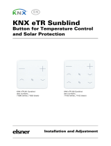
PRG
Fig. 1
View from bottom
Temperature sensor

5 Display and operation at the device
Room Temperature Controller KNX eTR 101-BA2 • Version: 11.07.2023 • Technical changes and errors excepted.
Option B: Display of target temperature or basic setpoint shift
Depending on the setting, the current target value or the shift relative to the base
setpoint is displayed. The temperature can be changed by touching the +/- buttons.
Target value display (absolute value):
Display of the basic setpoint shift (change compared to the basic setpoint of the
control):
Tap +:
Increase room temperature
(target temperature is
increased)
Tap -:
Lower room temperature
(target temperature is lowered)
Tap +:
Increase room temperature
(Basic setpoint shift direction
PLUS)
Tap -:
Lower room temperature
(Basic setpoint shift direction
MINUS)

6 Display and operation at the device
Room Temperature Controller KNX eTR 101-BA2 • Version: 11.07.2023 • Technical changes and errors excepted.
Option C: Display of actual temperature and target temperature/basic
setpoint shift
During normal operation, the current room temperature is displayed. By touching the
buttons, the display jumps to the target temperature or to the basic setpoint shift,
depending on the presetting. Changes with + or - are visible. The display returns to the
room temperature if no button is touched for 7 seconds.
Touch the + or - button briefly: The current target temperature (or the basic setpoint
shift) is displayed.
Tap +: Increase room temperature
(target temperature/basic setpoint shift is increased).
Tap -: Lower room temperature
(target temperature/basic setpoint shift is lowered).
General:
The step size for the change and the possible setting range are defined in the device
application (ETS). There you can also define whether the manually changed values are
retained after a mode change (e.g. Eco mode overnight) or reset to the stored values.
The button functions can be locked due to operating mode with priority 1.
or

7 Transfer protocol
Room Temperature Controller KNX eTR 101-BA2 • Version: 11.07.2023 • Technical changes and errors excepted.
6. Transfer protocol
Units:
Temperatures in degrees Celsius
6.1. List of all communication objects
Abbreviation flags:
C Communication
R Read
WWrite
T Transfer
UUpdate
No Text Function Flags DPT type Size
0 Software version Output R-CT [217.1] DPT_Ver-
sion
2 Bytes
5 LED brightness in % Input -WC- [5.1] DPT_Scal-
ing
1 Byte
6 Switch LED Input -WC- [1.1] DPT_Switch 1 Bit
7 Temperature sensor: malfunction Output R-CT [1.1] DPT_Switch 1 Bit
8 Temperature sensor: measured
value external
Input -WCT [9.1] DPT_Val-
ue_Temp
2 Bytes
9 Temperature sensor: measured
value
Output R-CT [9.1] DPT_Val-
ue_Temp
2 Bytes
10 Temperature sensor: measured
value total
Output R-CT [9.1] DPT_Val-
ue_Temp
2 Bytes
11 Temperature sensor: measured
value min./max. query
Input -WC- [1.17] DPT_Trig-
ger
1 Bit
12 Temperature sensor: measured
value minimum
Output R-CT [9.1] DPT_Val-
ue_Temp
2 Bytes
13 Temperature sensor: measured
value maximum
Output R-CT [9.1] DPT_Val-
ue_Temp
2 Bytes
14 Temperature sensor: measured
value min./max. reset
Input -WC- [1.17] DPT_Trig-
ger
1 Bit
15 Temp.control: HVAC mode (prior-
ity 1)
Input -WC- [20.102] DPT_H-
VACMode
1 Byte
16 Temp.control: HVAC mode (prior-
ity 2)
Input RWCT [20.102] DPT_H-
VACMode
1 Byte
17 Temp.control: Mode frost/heat
protection activt.
Input RWCT [1.1] DPT_Switch 1 Bit
18 Temp.control: Block (1 = Blocking) Input -WC- [1.1] DPT_Switch 1 Bit
19 Temp.control: Current setpoint Output R-CT [9.1] DPT_Val-
ue_Temp
2 Bytes

8 Transfer protocol
Room Temperature Controller KNX eTR 101-BA2 • Version: 11.07.2023 • Technical changes and errors excepted.
20 Temp.control: Switch. (0: Heating |
1: Cooling)
Input -WC- [1.1] DPT_Switch 1 Bit
21 Temp.control: Setpoint Comfort
heating
Input /
Output
RWCT [9.1] DPT_Val-
ue_Temp
2 Bytes
22 Temp.control: Setpoint Comfort
heat.(1:+ | 0:-)
Input -WC- [1.1] DPT_Switch 1 Bit
23 Temp.control: Setpoint Comfort
cooling
Input /
Output
RWCT [9.1] DPT_Val-
ue_Temp
2 Bytes
24 Temp.control: Setpoint Comfort
cool.(1:+ | 0:-)
Input -WC- [1.1] DPT_Switch 1 Bit
25 Temp.control: Basic 16-bit setpoint
shift
Input /
Output
RWCT [9.1] DPT_Val-
ue_Temp
2 Bytes
26 Temp.control: Setpoint Standby
heating
Input /
Output
RWCT [9.1] DPT_Val-
ue_Temp
2 Bytes
27 Temp.control: Setpoint Standby
heat.(1:+ | 0:-)
Input -WC- [1.1] DPT_Switch 1 Bit
28 Temp.control: Setpoint Standby
cooling
Input /
Output
RWCT [9.1] DPT_Val-
ue_Temp
2 Bytes
29 Temp.control: Setpoint Standby
cool. (1:+ | 0:-)
Input -WC- [1.1] DPT_Switch 1 Bit
30 Temp.control: Setpoint Eco heat-
ing
Input /
Output
RWCT [9.1] DPT_Val-
ue_Temp
2 Bytes
31 Temp.control: Setpoint Eco heat-
ing (1:+ | 0:-)
Input -WC- [1.1] DPT_Switch 1 Bit
32 Temp.control: Setpoint Eco cool-
ing
Input /
Output
RWCT [9.1] DPT_Val-
ue_Temp
2 Bytes
33 Temp.control: Setpoint Eco cool-
ing (1:+ | 0:-)
Input -WC- [1.1] DPT_Switch 1 Bit
34 Temp.control: Control variable
heating (level 1)
Output R-CT [5.1] DPT_Scal-
ing
1 Byte
35 Temp.control: Control variable
heating (level 2)
Output R-CT [5.1] DPT_Scal-
ing
1 Byte
36 Temp.control: Control variable
cooling (level 1)
Output R-CT [5.1] DPT_Scal-
ing
1 Byte
37 Temp.control: Control variable
cooling (level 2)
Output R-CT [5.1] DPT_Scal-
ing
1 Byte
38 Temperature control: Variable for
4/6-way valve
Output R-CT [5.1] DPT_Scal-
ing
1 Byte
39 Temp.control: Status Heat. level 1
(1=ON|0=OFF)
Output R-CT [1.1] DPT_Switch 1 Bit
40 Temp.control: Status Heat. level 2
(1=ON|0=OFF)
Output R-CT [1.1] DPT_Switch 1 Bit
41 Temp.control: Status Cool. level 1
(1=ON|0=OFF)
Output R-CT [1.1] DPT_Switch 1 Bit
No Text Function Flags DPT type Size

9 Transfer protocol
Room Temperature Controller KNX eTR 101-BA2 • Version: 11.07.2023 • Technical changes and errors excepted.
42 Temp.control: Status Cool. level 2
(1=ON|0=OFF)
Output R-CT [1.1] DPT_Switch 1 Bit
43 Temp.control: Comfort extension
status
Input /
Output
RWCT [1.1] DPT_Switch 1 Bit
44 Temp.control: Comfort Extension
time
Input RWCT [7.5] DPT_Time-
PeriodSec
2 Bytes
45 Temp. threshold value 1: Meas-
ured value
Input -WC- [9.1] DPT_Val-
ue_Temp
2 Bytes
46 Temp. thresholdV 1: Absolute
value
Input /
Output
RWCT [9.1] DPT_Val-
ue_Temp
2 Bytes
47 Temp. thresholdV 1: (1:+ | 0:-) Input -WC- [1.1] DPT_Switch 1 Bit
48 Temp. thresholdV 1: Switching
delay from 0 to 1
Input -WC- [7.5] DPT_Time-
PeriodSec
2 Bytes
49 Temp. thresholdV 1: Switching
delay from 1 to 0
Input -WC- [7.5] DPT_Time-
PeriodSec
2 Bytes
50 Temp. thresholdV 1: Switching
output
Output R-CT [1.1] DPT_Switch 1 Bit
51 Temp. thresholdV 1: Switching
output block
Input -WC- [1.1] DPT_Switch 1 Bit
52 Temp. threshold value 2: Meas-
ured value
Input -WC- [9.1] DPT_Val-
ue_Temp
2 Bytes
53 Temp. thresholdV 2: Absolute
value
Input /
Output
RWCT [9.1] DPT_Val-
ue_Temp
2 Bytes
54 Temp. thresholdV 2: (1:+ | 0:-) Input -WC- [1.1] DPT_Switch 1 Bit
55 Temp. thresholdV 2: Switching
delay from 0 to 1
Input -WC- [7.5] DPT_Time-
PeriodSec
2 Bytes
56 Temp. thresholdV 2: Switching
delay from 1 to 0
Input -WC- [7.5] DPT_Time-
PeriodSec
2 Bytes
57 Temp. thresholdV 2: Switching
output
Output R-CT [1.1] DPT_Switch 1 Bit
58 Temp. thresholdV 2: Switching
output block
Input -WC- [1.1] DPT_Switch 1 Bit
59 Push button 1 long-term Output R-CT [1.8] DPT_Up-
Down
1 Bit
60 Push button 1 short-term Output R-CT [1.10] DPT_Start 1 Bit
61 Push button 1 switching Output R-CT [1.1] DPT_Switch 1 Bit
62 Push button 1 dimming Input /
Output
RWCT [3.7] DPT_Con-
trol_Dimming
4 Bit
63 Push button 1 encoder 8 bit Output R-CT [5.10] DPT_Val-
ue_1_Ucount
1 Byte
64 Push button 1 encoder 16 bit Output R-CT [9.7] DPT_Val-
ue_Humidity
2 Bytes
No Text Function Flags DPT type Size

10 Setting the parameters
Room Temperature Controller KNX eTR 101-BA2 • Version: 11.07.2023 • Technical changes and errors excepted.
7. Setting the parameters
7.1. Behaviour on power failure/ restoration of
power
Behaviour following a failure of the bus power supply:
The device sends nothing.
65 Push button 1 Scene (recall and
save)
Output R-CT [17.1] DPT_
SceneNumber
[18.1] DPT_
SceneControl
1 Byte
66 Push button 1 NTC measured
value
Output R-CT [9.1] DPT_Val-
ue_Temp
2 Bytes
67 Push button 1 NTC external meas-
ured value
Input -WC- [9.1] DPT_Val-
ue_Temp
2 Bytes
68 Push button 1 NTC total measured
value
Output R-CT [9.1] DPT_Val-
ue_Temp
2 Bytes
69 Push button 1 NTC fault Output R-CT [1.1] DPT_Switch 1 Bit
70 Push button 2 long-term Output R-CT [1.8] DPT_Up-
Down
1 Bit
71 Push button 2 short-term Output R-CT [1.10] DPT_Start 1 Bit
72 Push button 2 switching Output R-CT [1.1] DPT_Switch 1 Bit
73 Push button 2 dimming Input /
Output
RWCT [3.7] DPT_Con-
trol_Dimming
4 Bit
74 Push button 2 encoder 8 bit Output R-CT [5.10] DPT_Val-
ue_1_Ucount
1 Byte
75 Push button 2 encoder 16 bit Output R-CT [9.7] DPT_Val-
ue_Humidity
2 Bytes
76 Push button 2 Scene (recall and
save)
Output R-CT [17.1] DPT_
SceneNumber
[18.1] DPT_
SceneControl
1 Byte
77 Push button 2 NTC measured
value
Output R-CT [9.1] DPT_Val-
ue_Temp
2 Bytes
78 Push button 2 NTC external meas-
ured value
Input -WC- [9.1] DPT_Val-
ue_Temp
2 Bytes
79 Push button 2 NTC total measured
value
Output R-CT [9.1] DPT_Val-
ue_Temp
2 Bytes
80 Push button 2 NTC fault Output R-CT [1.1] DPT_Switch 1 Bit
No Text Function Flags DPT type Size

11 Setting the parameters
Room Temperature Controller KNX eTR 101-BA2 • Version: 11.07.2023 • Technical changes and errors excepted.
Behaviour on bus restoration of power and following programming or reset:
The device sends all outputs according to their send behaviour set in the parameters
with the delays established in the "General settings" parameter block.
7.2. General settings
Set basic characteristics for the data transfer.
Set the initial value for LED brightness. Determine if the LED display should be con-
trolled via objects. This activates input objects 5 and 6 for LED brightness. And set
whether the LEDs switch off automatically after pressing a push button.
7.3. Temperature measured value
Determine is a malfunction object should be used. This activates output object 7 for
error messages.
When measuring temperature, the self-heating of the device is considered by the
electronics. The heating is compensated for in the device.
Use Offsets to adjust the readings to be sent.
Measurement variations from permanent sources of interference can be corrected in
this way.
The unit can calculate a mixed value from its own reading and an external value. Set
the mixed value calculation if desired.
If an external portion is used, all of the following settings are related to the overall read-
ing. The display of KNX eTR 101-BA2 also shows the total measured value.
Send delay in seconds after reset and bus
voltage recovery
5...7200
Maximum message rate • 1 message per second
• ...
• 10 messages per second
• ...
• 50 messages per second
Initial LED brightness in % until first com-
munication
0...100; 10
Control LEDs with objects No • Yes
Use automatic switching off of the LEDs
after using the push button
No • Yes
Switching off after (if automatic switch off
is used)
1 ... 255; 2 Sec. after operation
Use malfunction object No • Yes
Offset in 0.1°C -50…50; 0
Use external reading No • Yes

12 Setting the parameters
Room Temperature Controller KNX eTR 101-BA2 • Version: 11.07.2023 • Technical changes and errors excepted.
The minimum and maximum readings can be saved and sent to the bus. Use the
‘Reset temperature min/max. value’ object to reset the values to the current readings.
The values are not retained after a reset.
7.4. Temperature PI controller
Activate the control if you would like to use it.
General rules
Decide in which cases nominal values and delay times received per object are to be
kept. The parameter is only taken into consideration if the setting by object is activated
further down. Please note that the setting "After power restoration and programming"
should not be used for the initial start-up, as the factory settings are always used until
the first call (setting via objects is ignored).
Comfort, standby, eco and building protection modes may be used as necessary to
control room temperature.
Comfort when present,
Standby when absent,
Eco as a night-time mode and
Frost / heat protection (building protection) e.g. when the window is open.
The settings for the temperature control include the set point temperatures for the in-
dividual modes. Objects are used to determine which mode is to be selected. A change
of modes may be triggered manually or automatically (e.g. through a timer, window
contact).
Ext. Measured value portion of the total
reading
5% • 10% • ... • 50% • ... • 95% • 100%
All following settings refer to the total measured value
Transmission pattern for and total meas-
urements
• never
• periodically
• on change
• on change and periodically
on change of
(if sent on change)
0.1°C • 0.2°C • 0.5°C • 1.0°C • 2.0°C • 5.0°C
Send cycle
(if sent periodically)
5 s • 10 s • ... • 1.5 h • 2 h
Use minimum and maximum value No • Yes
Use controller No • Yes
The set points and delay times received via
the communication object should remain:
• never
• after power restoration
• after restoration of power and program-
ming

13 Setting the parameters
Room Temperature Controller KNX eTR 101-BA2 • Version: 11.07.2023 • Technical changes and errors excepted.
The mode may be switched with two 8 bit objects of different priority. Objects
'... HVAC mode (Prio 2)’ for switching in everyday operation and
'... HVAC mode (Prio 1)’ for central switching with higher priority.
The objects are coded as follows:
0 = Auto (only on Prio 1)
1 = Comfort
2 = Standby
3 = Eco
4 = Building protection
Alternatively, you can use three objects, with one object switching between eco and
standby mode and the two others are used to activate comfort mode or frost/heat pro-
tection mode. The comfort object then blocks the eco/standby object, and frost/heat
protection objects have the highest priority. Objects
'... Mode (1: Eco, 0: Standby)’,
'... comfort mode activation: and
'... frost/heat protection mode activation’
Select the mode to be activated after reset (e.g. power failure, reset of the line via
the bus). (Default).
Then configure a temperature control block using the blocking object.
Specify when the current control variables are to be sent to the bus. Periodic trans-
mission is safer if a message does not reach the recipient. You may also set up period-
ical monitoring by the actuator with this setting.
Switch mode via • two 8-bit objects (HVAC modes)
• three 1-bit objects
Mode after reset • Comfort
• Standby
• Eco
• Building protection
Behaviour of the blocking object with value • 1 = Block | 0 = Release
• 0 = Block | 1 = Release
Value of the blocking object after reset 0 • 1
Send control variable • on change
• on change and periodically
from change of (in absolute %) 1...10; 2
Cycle
(if sent periodically)
5 s • ... • 5 min • … • 2 h

14 Setting the parameters
Room Temperature Controller KNX eTR 101-BA2 • Version: 11.07.2023 • Technical changes and errors excepted.
The status object reports the current status of the output (0% = OFF, >0% = ON) and
may for example be used for visualisation, or to switch off the heating pump as soon
as the heating is switched off.
Then define the type of control. Heating and/or cooling may be controlled in two stag-
es.
General set point values
You may enter separate set point values for each mode or use the comfort set point as
a basic value.
If you are using the controls for both heating and cooling, you may also select the set-
ting "separately with switching object". Systems used for cooling in the summer and
for heating in the winter can thus be switched from one to the other.
If you are using the basic value, only the deviation from the comfort set point value is
listed for the other modes (e. g., 2°C less for standby mode).
Determine, which value must be shown on the display.
Actual value only means that the currently measured temperature value (or the mixed
value defined) is displayed. A set point change using buttons is then not possible.
Set point/base shift only means that the currently valid set point (e.g. 21.5 °C) or the
base set point shift (e.g. +2 °C) is displayed, depending on the set point settings. Use
the buttons to change the set point or the base set point shift.
Send status objects • on change
• on change to 1
• on change to 0
• on change and periodically
• on change to 1 and periodically
• on change to 0 and periodically
Cycle
(if sent periodically)
5 s • ... • 5 min • … • 2 h
Type of control • Single-stage heating
• Dual-stage heating
• Single-stage cooling
• Single-stage heating + single-stage cooling
• Dual-stage heating + single-stage cooling
• Dual-stage heating + dual-stage cooling
Keep modified set points after mode
change
No • Yes
Setting the set points • with separate set points
with switching object
• with separate set points
without switching object
• with comfort set point as a basis
with switching object
• with comfort set point as a basis
without switching object

15 Setting the parameters
Room Temperature Controller KNX eTR 101-BA2 • Version: 11.07.2023 • Technical changes and errors excepted.
Actual value and set point/base shift displays the actual value in normal functioning
conditions. If the + or - buttons are touched, the set point or the base set point shift are
displayed. The set point/base shift view closes after 7 seconds of inactivity, after which
the display switches back to the actual value.
If a switching object is used, define the behaviour and the value after reset.
The grades for the set point changes are predefined.
The control can be switched to comfort mode from eco mode, also night-time opera-
tion, via the comfort extension. This allows the user to maintain the nominal comfort
set point for a longer time, e.g. when having guests. The duration of this comfort ex-
tension period is set here. After the comfort extension period is terminated, the system
returns to eco mode.
Set point for comfort
Comfort mode is usually used for day-time operation when people are present. A start-
ing value is defined for the comfort set point as well as a temperature range in which
the nominal value may be modified.
If set point values are entered separately:
If the comfort set point value is used as a basis:
If the comfort set point value is used as a basis, an increase/decrease relative to this
value is set.
Display mode • Actual value only
• Set point/base shift only
• Actual and set point/Base shift
Behaviour of the switching object at
(with switching object)
• 0 = Heating | 1 = Cooling
• 1 = Heating | 0 = Cooling
Value of the switching object after reset
(with switching object)
0 • 1
Grading for set point changes
(in 0.1 °C)
1… 50; 10
Comfort extension time in seconds
(can only be activated in eco mode)
1…36000; 3600
Initial heating/cooling set point (in 0.1 °C)
valid until first communication
-300…800; 210
Min. object value heating/cooling (in 0.1 °C) -300…800; 160
Max. object value heating/cooling (in 0.1 °C) -300…800; 280
Heating initial set point (in 0.1 °C)
valid until first communication
-300…800; 210
Minimum base set point (in 0.1°C) -300…800; 160
Maximum base set point (in 0.1°C) -300…800; 280

16 Setting the parameters
Room Temperature Controller KNX eTR 101-BA2 • Version: 11.07.2023 • Technical changes and errors excepted.
If the comfort set point is used as the basis, but no switching object is used, a dead
zone is determined for the control mode ‘heating and cooling’ to avoid direct switching
from heating to cooling.
Set point for standby
Standby mode is usually used for daytime mode when people are absent.
If set point values are entered separately:
A starting set point value is defined as well as a temperature range in which the set
point value may be changed.
If the comfort set point value is used as a basis:
If the comfort set point value is used as a basis, an increase/decrease relative to this
value is set.
Eco set point
Eco mode is usually used for night-time operation.
If set point values are entered separately:
A starting set point value is defined as well as a temperature range in which the set
point value may be changed.
Reduction by up to (in 0.1°C) 1…100; 50
Increase by up to (in 0.1°C) 1…100; 50
Dead zone between heating and cooling
(in 0.1°C)
(only if both heating and cooling are used,
without switching object)
1…100; 50
Heating initial set point (in 0.1 °C)
valid until first communication
-300…800; 180
Cooling initial set point (in 0.1 °C)
valid until first communication
-300…800; 240
Min. object value heating/cooling (in 0.1 °C) -300…800; 160
Max. object value heating/cooling (in 0.1 °C) -300…800; 280
Reduce heating set point (in 0.1°C)
(for heating)
0…200; 30
Increase cooling set point (in 0.1°C)
(for cooling)
0…200; 30
Heating initial set point (in 0.1 °C)
valid until first communication
-300…800; 160
Cooling initial set point (in 0.1 °C)
valid until first communication
-300…800; 280
Min. object value heating/cooling (in 0.1 °C) -300…800; 160
Max. object value heating/cooling (in 0.1 °C) -300…800; 280

17 Setting the parameters
Room Temperature Controller KNX eTR 101-BA2 • Version: 11.07.2023 • Technical changes and errors excepted.
If the comfort set point value is used as a basis:
If the comfort set point value is used as a basis, an increase/decrease relative to this
value is set.
Set point values for frost/heat protection (building protection)
The building protection mode is used, for example, when windows are opened for ven-
tilation. Set points for frost protection (heating) and heat protection (cooling) are de-
termined which may not be modified from outside (no access via operating devices
etc.). The building protection mode may be activated with delay, which allows you to
leave the building before the controls switch to frost/heat protection mode.
General actuating variables
This setting only appears for the ‘heating and cooling’ control types. This is where you
can decide whether to use a shared variable for heating and cooling. If the 2nd stage
has a common variable, this is also where you determine the control mode of the 2nd
stage.
When using the actuating variable for a 4/6-way valve the following applies:
0%...100% heating = 66%...100% actuating variable
OFF = 50% actuating variable
0%...100% cooling = 33%...0% actuating variable
Reduce heating set point (in 0.1°C)
(for heating)
0…200; 50
Increase cooling set point (in 0.1°C)
(for cooling)
0…200; 60
Nominal value frost protection\r\n(in 0,1°C) -300…800; 70
Activation delay none • 5 s • ... • 5 min • … • 2 h
Nominal value heat protection (in 0,1°C) -300…800; 350
Activation delay none • 5 s • ... • 5 min • … • 2 h
For heating and cooling • separate actuating variables are used
• common variables are used for
Stage 1
• common variables are used for
Stage 2
• common variables are used for
Stage 1+2
Use actuating variable for 4/6-way valve
(only for shared actuating variable on stage 1)
No • Yes
Control type
(for stage 2 only)
• 2-point control
• PI control
Regulating variable of the 2nd stage is on
(for stage 2 with 2-point control only)
• 1-bit object
• 8-bit object

18 Setting the parameters
Room Temperature Controller KNX eTR 101-BA2 • Version: 11.07.2023 • Technical changes and errors excepted.
7.4.1. Heating control stage 1/2
If a heating control mode is configured, one or two setting sections for the heating
stages are displayed.
In the first stage, heating is controlled by a PI controller which allows to either enter
control parameters or select predetermined applications. For explanations of the pa-
rameters, see sections PI control with controller parameters and the application spec-
ified.
In the second stage (thus only in the case of 2-stage heating), heating is controlled via
a PI or a 2-point-control. For explanations of the parameters, see the corresponding
sections.
On stage 2, the set point deviation between the two stages must also be specified, i.e.
beyond which set point undershoot the second stage is added.
PI control with controller parameters
This setting allows individual input of the parameters for PI control.
Specify the deviation from the set point value at which the maximum control variable
value is reached, i.e. the point at which maximum heating power is activated.
Reset time shows how quickly the controller responds to deviations from the set point.
In the case of a short reset time, the control responds with a fast increase of the control
variable. In the case of a long reset time, the control responds slower and needs longer
until the necessary control variable for the set point deviation is reached.
You should set the time appropriate for the heating system at this point (observe the
manufacturer's instructions).
Setting of the controller by • Controller parameter
• Specified applications
Set point difference between 1st and 2nd
stages (in 0.1°C)
(for stage 2)
0...100; 40
Control type
(for stage 2, no shared actuating variables)
• 2-point control
• PI control
Control variable is on
(for stage 2 with 2-point control, no shared
actuating variables)
• 1-bit object
• 8-bit object
Control type • PI control
Setting of the controller by • Controller parameter
• Specified applications
Maximum control variable is reached
at set point/actual difference of (in °C)
1...5
Reset time (in min) 1...255; 30
/