Page is loading ...

EN
Installation and Adjustment
KNX eTR Light
Button for Temperature Control
and Light
KNX eTR 205 Light
Item numbers
71160 (white), 71162 (black)
KNX eTR 206 Light
Item numbers
71170 (white), 71172 (black)


1 Contents
Elsner Elektronik GmbH • Sohlengrund 16 • 75395 Ostelsheim • Germany
KNX eTR 205/206 Light push button • from application 1.0
Version: 11.07.2023 • Technical changes and errors excepted.
1. Safety and operating instructions ....................................................... 3
2. Description ........................................................................................... 3
2.0.1. Area function ................................................................................................. 4
3. Commissioning .................................................................................... 5
3.1. Addressing of the device at the bus ....................................................................... 5
4. Display and operation at the device .................................................... 6
4.1. Adjust room temperature (using the example KNX eTR 205 Light) .................... 6
5. Transmission protocol ......................................................................... 9
5.1. List of all communication objects ........................................................................... 9
6. Setting the parameters ...................................................................... 13
6.1. Behaviour on power failure/ restoration of power .............................................. 13
6.2. General settings ..................................................................................................... 13
6.3. Temperature measured value ............................................................................... 13
6.4. Temperature threshold values .............................................................................. 14
6.4.1. Threshold value 1, 2 ................................................................................... 14
6.5. Temperature PI controller ...................................................................................... 16
6.5.1. Heating control stage 1/2 ........................................................................... 22
6.5.2. Cooling control stage 1/2 ........................................................................... 24
6.5.3. Fan Coil Control .......................................................................................... 26
6.6. LEDs ......................................................................................................................... 27
6.7. Buttons .................................................................................................................... 28
6.7.1. Light 1 / 2 ..................................................................................................... 28
6.8. Logic ........................................................................................................................ 29
6.8.1. AND logic outputs 1/2 and OR logic outputs 1/2 ...................................... 29
6.8.2. OR LOGIC connection inputs ..................................................................... 31

2 Clarification of signs
This manual is amended periodically and will be brought into line with new software
releases. The change status (software version and date) can be found in the contents footer.
If you have a device with a later software version, please check
www.elsner-elektronik.de in the menu area "Service" to find out whether a more up-to-
date version of the manual is available.
Clarification of signs used in this manual
Safety advice.
Safety advice for working on electrical connections, components,
etc.
DANGER! ... indicates an immediately hazardous situation which will lead to
death or severe injuries if it is not avoided.
WARNING! ... indicates a potentially hazardous situation which may lead to
death or severe injuries if it is not avoided.
CAUTION! ... indicates a potentially hazardous situation which may lead to
trivial or minor injuries if it is not avoided.
ATTENTION! ... indicates a situation which may lead to damage to property if it is
not avoided.
ETS In the ETS tables, the parameter default settings are marked by
underlining.

3 Safety and operating instructions
KNX eTR 205/206 Light push button • Version: 11.07.2023 • Technical changes and errors excepted.
1. Safety and operating instructions
Installation, testing, operational start-up and troubleshooting should
only be performed by an authorised electrician.
CAUTION!
Live voltage!
• Inspect the device for damage before installation. Only put undamaged
devices into operation.
• Comply with the locally applicable directives, regulations and provisions for
electrical installation.
• Immediately take the device or system out of service and secure it against
unintentional switch-on if risk-free operation is no longer guaranteed.
Use the device exclusively for building automation and observe the operating
instructions. Improper use, modifications to the device or failure to observe the
operating instructions will invalidate any warranty or guarantee claims.
Operate the device only as a fixed-site installation, i.e. only in assembled condition and
after conclusion of all installation and operational start-up tasks, and only in the
surroundings designated for it.
Elsner Elektronik is not liable for any changes in norms and standards which may occur
after publication of these operating instructions.
For information on installation, maintenance, disposal, scope of deliv-
ery and technical data, please refer to the installation instructions.
2. Description
The KNX eTR 205/206 Light push button has touch-sensitive buttons with which
functions can be called up in the KNX building bus system. The glass surface is printed
with areas for setting the temperature and light. LEDs are integrated in these areas and
their behaviour can be adjusted.
A temperature sensor is integrated into KNX eTR 205/206 Light. An external tem-
perature reading can be received via the bus and processed with its own data to create
a total temperature (mixed value).
The KNX eTR 205/206 Light has a PI controller for heating and cooling. The setpoint
temperature can be changed using the "+" and "-" touch buttons.
Communication objects can be linked via AND and OR logic gates.
Functions:
•Operating zone for temperature control with 2 areas (warmer, cooler)

4 Description
KNX eTR 205/206 Light push button • Version: 11.07.2023 • Technical changes and errors excepted.
•LEDs can be set. All LEDs Off, all LEDs as ambient lighting, all LEDs
individually controllable
•Area function when touching two or more push buttons. Can be configured
as switch, selector switch, as 8 or 16 bit encoder or for scenario recall
•Temperature measurements. Mixed value from own measured value and
external values (proportion can be set by percentage), output of minimum and
maximum values
•PI-controller for heating (one or two-level) and cooling (one or two-level)
according to temperature. Regulation according to separate setpoints or basic
setpoint temperature
•2 AND and 2 OR logic gates each with 4 inputs. 8 logic inputs (in the form
of communications objects) can be used as inputs for the logic gates. The
output from each gate can be configured optionally as 1-bit or 2 x 8-bit
Additional functions KNX eTR 205 Light:
•1 operating zone for light with 2 areas (switching/dimming with short/long
distinction)
Additional functions KNX eTR 206 Light:
•2 operating zones for light with 2 areas (switching/dimming with short/long
distinction)
2.0.1. Area function
If the area function in ETS has been activated, another function is available alongside
the regular key functions. This is triggered by touching multiple keys, e.g. if you touch
the sensor with the palm of your hand.
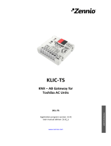
Using the area function
If a key is pressed and another (different) key is touched within 0.2 seconds, the action
set in the ETS is performed for the area operation (See Fig. 1 a) and b)). The keys are
then blocked for 0.5 seconds.
Using the normal key function
If a key is pressed and no other key is touched within 0.2 seconds, the normal key
function is enabled/provided for 5 seconds (See Fig. 1 c) and d)). This is extended for 5
seconds with each push of the button.

5 Commissioning
KNX eTR 205/206 Light push button • Version: 11.07.2023 • Technical changes and errors excepted.
If the area function in the ETS is disabled, the keys can be used normally at any time.
3. Commissioning
Configuration is made using the KNX software as of ETS 5. The product file can be
downloaded from the ETS online catalogue and the Elsner Elektronik website on
www.elsner-elektronik.de.
After the bus voltage has been applied, the device will enter an initialisation phase last-
ing approx. 5 seconds. During this phase no information can be received or sent via the
bus.
3.1. Addressing of the device at the bus
The equipment is delivered with the bus address 15.15.255. Another address can be
programmed using the ETS.
The programming button is located at the bottom outer side of the front panel of the
device and is recessed. Use a thin object to reach the button, e. g. a 1.5 mm² wire.
Key function readiness
Key function readiness
Fig. 1
0s 0.2s 5.2s
Key Y
Key X
Key X
Design
Function Y
Key function readiness
Area function
Examples of normal key functions
0.5 s block
Key X
Design
Area function
Key Y
Design
Function X
a)
b)
c)
d)
Key X
Key Y 0.5 s block
Design
Area function
Area function examples
readiness

6 Display and operation at the device
KNX eTR 205/206 Light push button • Version: 11.07.2023 • Technical changes and errors excepted.
When programming mode is active, the programming LED lights up and all other LEDs
also flash.
4. Display and operation at the device
4.1. Adjust room temperature (using the example
KNX eTR 205 Light)
Depending on the setting of the "Display mode" parameter in the device application,
the KNX eTR 205/206 Light push button displays the current room temperature
value (or mixed value), the target value or the shift in relation to the basic setpoint. The
display can be dimmed and switched off via the bus so that no value is displayed.
Option A: Display of actual temperature (room temperature)
The current room temperature is displayed. It is not possible to change the room
temperature manually using the +/- buttons.
Option B: Display of target temperature or basic setpoint shift
Depending on the setting, the current target value or the shift relative to the base
setpoint is displayed. The temperature can be changed by touching the +/- buttons.
Target value display (absolute value):
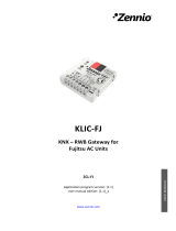
PRG
Fig. 2
View from bottom
Temperature sensor
Tap +:
Increase room temperature
(target temperature is
increased)
Tap -:
Lower room temperature
(target temperature is lowered)

7 Display and operation at the device
KNX eTR 205/206 Light push button • Version: 11.07.2023 • Technical changes and errors excepted.
Display of the basic setpoint shift (change compared to the basic setpoint of the
control):
Option C: Display of actual temperature and target temperature/basic
setpoint shift
During normal operation, the current room temperature is displayed. By touching the
buttons, the display jumps to the target temperature or to the basic setpoint shift,
depending on the presetting. Changes with + or - are visible. The display returns to the
room temperature if no button is touched for 7 seconds.
Touch the + or - button briefly: The current target temperature (or the basic setpoint
shift) is displayed.
Tap +: Increase room temperature
(target temperature/basic setpoint shift is increased).
Tap -: Lower room temperature
(target temperature/basic setpoint shift is lowered).
Tap +:
Increase room temperature
(Basic setpoint shift direction
PLUS)
Tap -:
Lower room temperature
(Basic setpoint shift direction
MINUS)
or

8 Display and operation at the device
KNX eTR 205/206 Light push button • Version: 11.07.2023 • Technical changes and errors excepted.
General:
The step size for the change and the possible setting range are defined in the device
application (ETS). There you can also define whether the manually changed values are
retained after a mode change (e.g. Eco mode overnight) or reset to the stored values.
The button functions can be disabled in the ETS or locked due to operating mode with
priority 1.

9 Transmission protocol
KNX eTR 205/206 Light push button • Version: 11.07.2023 • Technical changes and errors excepted
5. Transmission protocol
Units:
Temperatures in degrees Celsius
5.1. List of all communication objects
Abbreviations Flags:
C Communication
R Read
WWrite
T Transmit
UUpdate
No Text Function Flags DPT type Size
0 Software version Output R-CT [217.1] DPT_Ver-
sion
2 Bytes
20 Temperature sensor: malfunction Output R-CT [1.1] DPT_Switch 1 Bit
21 Temperature sensor: measured
value external
Input -WCT [9.1] DPT_Val-
ue_Temp
2 Bytes
22 Temperature sensor: measured
value
Output R-CT [9.1] DPT_Val-
ue_Temp
2 Bytes
23 Temperature sensor: measured
value total
Output R-CT [9.1] DPT_Val-
ue_Temp
2 Bytes
24 Temperature sensor: measured
value min./max. query
Input -WC- [1.17] DPT_Trig-
ger
1 Bit
25 Temperature sensor: measured
value minimum
Output R-CT [9.1] DPT_Val-
ue_Temp
2 Bytes
26 Temperature sensor: measured
value maximum
Output R-CT [9.1] DPT_Val-
ue_Temp
2 Bytes
27 Temperature sensor: measured
value min./max. reset
Input -WC- [1.17] DPT_Trig-
ger
1 Bit
30 Temp. thresholdV 1: Absolute
value
Input /
Output
RWCT [9.1] DPT_Val-
ue_Temp
2 Bytes
31 Temp. thresholdV 1: (1:+ | 0:-) Input -WC- [1.1] DPT_Switch 1 Bit
32 Temp. thresholdV 1: Switching
delay from 0 to 1
Input -WC- [7.5] DPT_Time-
PeriodSec
2 Bytes
33 Temp. thresholdV 1: Switching
delay from 1 to 0
Input -WC- [7.5] DPT_Time-
PeriodSec
2 Bytes
34 Temp. thresholdV 1: Switching
output
Output R-CT [1.1] DPT_Switch 1 Bit
35 Temp. thresholdV 1: Switching
output block
Input -WC- [1.1] DPT_Switch 1 Bit
36 Temp. thresholdV 2: Absolute
value
Input /
Output
RWCT [9.1] DPT_Val-
ue_Temp
2 Bytes

10 Transmission protocol
KNX eTR 205/206 Light push button • Version: 11.07.2023 • Technical changes and errors excepted
37 Temp. thresholdV 2: (1:+ | 0:-) Input -WC- [1.1] DPT_Switch 1 Bit
38 Temp. thresholdV 2: Switching
delay from 0 to 1
Input -WC- [7.5] DPT_Time-
PeriodSec
2 Bytes
39 Temp. thresholdV 2: Switching
delay from 1 to 0
Input -WC- [7.5] DPT_Time-
PeriodSec
2 Bytes
40 Temp. thresholdV 2: Switching
output
Output R-CT [1.1] DPT_Switch 1 Bit
41 Temp. thresholdV 2: Switching
output block
Input -WC- [1.1] DPT_Switch 1 Bit
50 Temp.control: HVAC mode (prior-
ity 1)
Input /
Output
RWCT depending on
setting
1 Byte
51 Temp.control: HVAC mode (prior-
ity 2)
Input /
Output
RWCT depending on
setting
1 Byte
52 Temp.control: Mode frost/heat
protection activt.
Input RWCT [1.1] DPT_Switch 1 Bit
53 Temp.control: Block (1 = Blocking) Input -WC- [1.1] DPT_Switch 1 Bit
54 Temp.control: Current setpoint Output R-CT [9.1] DPT_Val-
ue_Temp
2 Bytes
55 Temp.control: Switch. (0: Heating |
1: Cooling)
Input -WC- [1.1] DPT_Switch 1 Bit
56 Temp.control: Setpoint Comfort
heating
Input /
Output
RWCT [9.1] DPT_Val-
ue_Temp
2 Bytes
57 Temp.control: Setpoint Comfort
heat.(1:+ | 0:-)
Input -WC- [1.1] DPT_Switch 1 Bit
58 Temp.control: Setpoint Comfort
cooling
Input /
Output
RWCT [9.1] DPT_Val-
ue_Temp
2 Bytes
59 Temp.control: Setpoint Comfort
cool.(1:+ | 0:-)
Input -WC- [1.1] DPT_Switch 1 Bit
60 Temp.control: Basic 16-bit setpoint
shift
Input -WC- [9.1] DPT_Val-
ue_Temp
2 Bytes
61 Temp.control: Setpoint Standby
heating
Input /
Output
RWCT [9.1] DPT_Val-
ue_Temp
2 Bytes
62 Temp.control: Setpoint Standby
heat.(1:+ | 0:-)
Input -WC- [1.1] DPT_Switch 1 Bit
63 Temp.control: Setpoint Standby
cooling
Input /
Output
RWCT [9.1] DPT_Val-
ue_Temp
2 Bytes
64 Temp.control: Setpoint Standby
cool. (1:+ | 0:-)
Input -WC- [1.1] DPT_Switch 1 Bit
65 Temp.control: Setpoint Eco heat-
ing
Input /
Output
RWCT [9.1] DPT_Val-
ue_Temp
2 Bytes
66 Temp.control: Setpoint Eco heat-
ing (1:+ | 0:-)
Input -WC- [1.1] DPT_Switch 1 Bit
67 Temp.control: Setpoint Eco cool-
ing
Input /
Output
RWCT [9.1] DPT_Val-
ue_Temp
2 Bytes
No Text Function Flags DPT type Size

11 Transmission protocol
KNX eTR 205/206 Light push button • Version: 11.07.2023 • Technical changes and errors excepted
68 Temp.control: Setpoint Eco cool-
ing (1:+ | 0:-)
Input -WC- [1.1] DPT_Switch 1 Bit
69 Temp.control: Control variable
heating (level 1)
Output R-CT [5.1] DPT_Scal-
ing
1 Byte
70 Temp.control: Control variable
heating (level 2)
Output R-CT [5.1] DPT_Scal-
ing
1 Byte
71 Temp.control: Control variable
cooling (level 1)
Output R-CT [5.1] DPT_Scal-
ing
1 Byte
72 Temp.control: Control variable
cooling (level 2)
Output R-CT [5.1] DPT_Scal-
ing
1 Byte
73 Temperature control: Variable for
4/6-way valve
Output R-CT [5.1] DPT_Scal-
ing
1 Byte
74 Temp.control: Status Heat. level 1
(1=ON|0=OFF)
Output R-CT [1.1] DPT_Switch 1 Bit
75 Temp.control: Status Heat. level 2
(1=ON|0=OFF)
Output R-CT [1.1] DPT_Switch 1 Bit
76 Temp.control: Status Cool. level 1
(1=ON|0=OFF)
Output R-CT [1.1] DPT_Switch 1 Bit
77 Temp.control: Status Cool. level 2
(1=ON|0=OFF)
Output R-CT [1.1] DPT_Switch 1 Bit
78 Temp.control: Comfort extension
status
Input /
Output
RWCT [1.1] DPT_Switch 1 Bit
79 Temp.control: Comfort Extension
time
Input RWCT [7.5] DPT_Time-
PeriodSec
2 Bytes
80 Temp. Controller: Fan coil levels 0
to 3
Output R-CT [5.1] DPT_Scal-
ing
1 Byte
81 Temp. Controller: Fan coil level 1 Output R-CT [1.1] DPT_Switch 1 Bit
82 Temp. Controller: Fan coil level 2 Output R-CT [1.1] DPT_Switch 1 Bit
83 Temp. Controller: Fan coil level 3 Output R-CT [1.1] DPT_Switch 1 Bit
84 Temp. Controller: Fan coil auto=1
manual=0
Input /
Output
RWCT [1.1] DPT_Switch 1 Bit
86 All LEDs On/Off Input -WC- [1.1] DPT_Switch 1 Bit
87 All LEDs Brightness Input -WC- [5.1] DPT_Scal-
ing
1 Byte
88 LEDs Temperature display On/Off Input -WC- [1.1] DPT_Switch 1 Bit
89 LEDs Temperature display Block Input -WC- [1.1] DPT_Switch 1 Bit
90 LED 1 on/off Input -WC- [1.1] DPT_Switch 1 Bit
91 LED 1 Block Input -WC- [1.1] DPT_Switch 1 Bit
92 LED 2 on/off Input -WC- [1.1] DPT_Switch 1 Bit
93 LED 2 Block Input -WC- [1.1] DPT_Switch 1 Bit
Only for KNX eTR 206 Light
94 LED 3 on/off Input -WC- [1.1] DPT_Switch 1 Bit
95 LED 3 Block Input -WC- [1.1] DPT_Switch 1 Bit
No Text Function Flags DPT type Size

12 Transmission protocol
KNX eTR 205/206 Light push button • Version: 11.07.2023 • Technical changes and errors excepted
96 LED 4 on/off Input -WC- [1.1] DPT_Switch 1 Bit
97 LED 4 Block Input -WC- [1.1] DPT_Switch 1 Bit
For all models
99 Area operation on/off Input -WC- [1.1] DPT_Switch 1 Bit
100 Area operation Output: Switch Output R-CT depending on
setting
2 Bytes
101 Light (1) switching Output R-CT [1.1] DPT_Switch 1 Bit
102 Light (1) dimming Output R-CT [3.7] DPT_Con-
trol_Dimming
4 Bit
Only for KNX eTR 206 Light
103 Light 2 switching Output R-CT [1.1] DPT_Switch 1 Bit
104 Light 2 dimming Output R-CT [3.7] DPT_Con-
trol_Dimming
4 Bit
For all models
107 Logic input 1 Input -WC- [1.2] DPT_Bool 1 Bit
108 Logic input 2 Input -WC- [1.2] DPT_Bool 1 Bit
109 Logic input 3 Input -WC- [1.2] DPT_Bool 1 Bit
110 Logic input 4 Input -WC- [1.2] DPT_Bool 1 Bit
111 Logic input 5 Input -WC- [1.2] DPT_Bool 1 Bit
112 Logic input 6 Input -WC- [1.2] DPT_Bool 1 Bit
113 Logic input 7 Input -WC- [1.2] DPT_Bool 1 Bit
114 Logic input 8 Input -WC- [1.2] DPT_Bool 1 Bit
117 AND logic 1: 1 bit switching output Output R-CT [1.2] DPT_Bool 1 Bit
118 AND logic 1: 8 bit output A Output R-CT depending on
setting
1 Byte
119 AND logic 1: 8 bit output B Output R-CT depending on
setting
1 Byte
120 AND logic 1: Block Input -WC- [1.1] DPT_Switch 1 Bit
121 AND logic 2: 1 bit switching output Output R-CT [1.2] DPT_Bool 1 Bit
122 AND logic 2: 8 bit output A Output R-CT depending on
setting
1 Byte
123 AND logic 2: 8 bit output B Output R-CT depending on
setting
1 Byte
124 AND logic 2: Block Input -WC- [1.1] DPT_Switch 1 Bit
125 OR logic 1: 1 bit switching output Output R-CT [1.2] DPT_Bool 1 Bit
126 OR logic 1: 8 bit output A Output R-CT depending on
setting
1 Byte
127 OR logic 1: 8 bit output B Output R-CT depending on
setting
1 Byte
128 OR logic 1: Block Input -WC- [1.1] DPT_Switch 1 Bit
129 OR logic 2: 1 bit switching output Output R-CT [1.2] DPT_Bool 1 Bit
No Text Function Flags DPT type Size

13 Setting the parameters
KNX eTR 205/206 Light push button • Version: 11.07.2023 • Technical changes and errors excepted
6. Setting the parameters
6.1. Behaviour on power failure/ restoration of
power
Behaviour following a failure of the bus power supply:
The device sends nothing.
Behaviour on bus restoration of power and following programming or reset:
The device sends all outputs according to their send behaviour set in the parameters
with the delays established in the "General settings" parameter block.
6.2. General settings
Set the basic properties of the data transmission.
6.3. Temperature measured value
Select, whether a malfunction object is to be sent if the sensor is faulty.
When measuring temperature, the self-heating of the device is considered by the
electronics. The heating is compensated for in the device.
Use Offsets to adjust the readings to be sent.
Permanent measurement variations can be corrected in this way.
130 OR logic 2: 8 bit output A Output R-CT depending on
setting
1 Byte
131 OR logic 2: 8 bit output B Output R-CT depending on
setting
1 Byte
132 OR logic 2: Block Input -WC- [1.1] DPT_Switch 1 Bit
Transmission delay after reset/bus restora-
tion
5 s • ... • 300 s
Maximum message rate • 1 message per second
• ...
• 10 messages per second
• ...
• 50 messages per second
Use malfunction object No • Yes
Offset in 0.1°C -50…50; 0
No Text Function Flags DPT type Size

14 Setting the parameters
KNX eTR 205/206 Light push button • Version: 11.07.2023 • Technical changes and errors excepted
The unit can calculate a mixed value from its own reading and an external value. Set
the mixed value calculation if desired. If an external portion is used, all of the following
settings (threshold values, etc.) are related to the overall reading.
The minimum and maximum readings can be saved and sent to the bus. Use the
"Reset temperature min/max. value" objects to reset the values to the current readings.
The values are not retained after a reset.
6.4. Temperature threshold values
Activate the required temperature threshold values. The menus for the further setting
of the threshold values are then displayed.
6.4.1. Threshold value 1, 2
Threshold value
Decide in which cases threshold values and delay times received are to be kept per
object. The parameter is only taken into consideration if the setting by object is activat-
ed further down. Please note that the setting "After power restoration and program-
ming" should not be used for the initial start-up, as the factory settings are always used
until the first call (setting via objects is ignored).
Set the threshold values directly in the application program using parameters, or de-
fine them via the bus using a communication object.
Threshold value setpoint using parameter:
Set the threshold values and hysteresis directly.
Threshold value setpoint using a communication object:
Beforehand, enter how the threshold value will be received from the bus. Basically, a
new value can be received, or simply a command to increase or decrease.
Use external measured value No • Yes
Ext. Reading proportion of the total reading 5% • 10% • ... • 50% • ... • 100%
Sending pattern for internal and total
measured value
• never
• periodically
• on change
• on change and periodically
At and above change of
(if sent on change)
0.1°C • 0.2°C • 0.5°C • ... • 5.0°C
Send cycle
(if sent periodically)
5 s • 10 s • ... • 2 h
Use minimum and maximum value No • Yes
Use threshold value 1 / 2 Yes • No
Threshold value setpoint using Parameter • Communication objects
Threshold in 0.1°C -300… 800; 200

15 Setting the parameters
KNX eTR 205/206 Light push button • Version: 11.07.2023 • Technical changes and errors excepted
During initial commissioning, a threshold value must be defined which will be valid un-
til the first call with a new threshold value. For units which have already been taken into
service, the last communicated threshold value can be used. Basically, a temperature
range is given in which the threshold value can be changed (object value limit).
A set threshold value will be retained until a new value or a change is transferred. The
current value is saved in so that it is retained in the event of a power supply failure and
will be available again once the power supply is restored.
Set the hysteresis independently of the type of threshold value setting.
Switching output
Set the behaviour of the switching output when a threshold value is exceeded/under-
cut. The output switching delay can be set using objects or directly as a parameter.
Threshold value setpoint using Parameter • Communication objects
The last communicated value should • never
• after restoration of power
• after power restoration and
Programming
Start threshold value in 0.1°C
valid until first Communication
-300 … 800; 200
Object value limit (min) in 0.1°C -300…800
Object value limit (max) in 0.1°C -300…800
Type of threshold value change Absolute value • Increase/decrease
Interval
(upon increase/decrease change)
0.1 °C • ... • 5°C
Hysteresis in % of the threshold value 0 … 50; 20
Hysteresis in 0.1°C 0 … 1100; 50
When the following conditions apply, the
output is
(TV = Threshold value)
• TV above = 1 | TV - Hyst. below = 0
• LV above = 0 |LV - hysteresis below = 1
• TV below = 1 |TV + hysteresis above = 0
• TV below = 0 |TV + hysteresis above = 1
Delays can be set via objects
(in seconds)
No • Yes
Switching delay from 0 to 1
(if delay is adjustable via objects: valid until
1st communication)
None • 1 s • 2 s • 5 s • 10 s • … • 2 h
Switching delay from 1 to 0
(if delay is adjustable via objects: valid until
1st communication)
None • 1 s • 2 s • 5 s • 10 s • … • 2 h

16 Setting the parameters
KNX eTR 205/206 Light push button • Version: 11.07.2023 • Technical changes and errors excepted
Block
The switching output can be blocked using an object.
Set the cases in which threshold vlaues and delay times received per object are to be
retained.
The behaviour of the switching output on release is dependent on the value of the pa-
rameter "Switching output sends" (see "Switching output")
6.5. Temperature PI controller
Activate the controller if you want to use it.
Switching output sends • on change
• on change to 1
• on change to 0
• on change and periodically
• on change to 1 and periodically
• on change to 0 and periodically
Cycle
(is sent only if "periodically" is selected)
5 s • 10 s • 30 s… • 2 h
Use switching output block No • Yes
Assessment of the block object • At value 1: block | At value 0: release
• At value 0: block | At value 1: release
Blocking object value before first Commu-
nication
0 • 1
Switching output behaviour
On blocking • Do not send message
• 0 Send
• 1 Send
On release
(with 2 second release delay)
[Dependent on the "Switching output
sends" setting]
Switching output sends on change • Do not send message
• Send switching output status
Switching output sends on change to 1 • Do not send message
• if switching output = 1 send 1
Switching output sends on change to 0 • Do not send message
• if switching output = 0 send 0
Switching output sends on change and
periodically
Send switching output status
Switching output sends on change to 1 and
periodically
if switching output = 1 send 1
Switching output sends on change to 0 and
periodically
if switching output = 0 send 0
Use controller No • Yes

17 Setting the parameters
KNX eTR 205/206 Light push button • Version: 11.07.2023 • Technical changes and errors excepted
General rules
Decide in which cases nominal values and delay times received per object are to be
kept. The parameter is only taken into consideration if the setting by object is activated
further down. Please note that the setting "After power restoration and programming"
should not be used for the initial start-up, as the factory settings are always used until
the first call (setting via objects is ignored).
For an adequate regulation of the indoor temperature, comfort, standby, eco and build-
ing protection modes may be used.
Comfort when present,
Standby when absent,
Eco as a night-time mode and
Frost / heat protection (building protection) e.g. when the window is open.
The settings for the temperature control include the setpoint temperatures for the in-
dividual modes. Objects are used to determine which mode is to be selected. A change
of mode may be triggered manually or automatically (e.g. by a timer, window contact).
The mode may be switched with two 8 bit objects of different priority. Objects
„... HVAC mode (Prio 2)“ for switching in everyday operation and
„... HVAC mode (Prio 1)“ for central switching with higher priority.
The objects are coded as follows:
0 = Auto
1 = Comfort
2 = Standby
3 = Eco
4 = Building protection
Alternatively, you can use three objects, with one object switching between eco and
standby mode and the two others are used to activate comfort mode or frost/heat pro-
tection mode. The comfort object then blocks the eco/standby object, and frost/heat
protection objects have the highest priority. Objects
„... Mode (1: Eco, 0: Standby)“,
„... comfort activation mode" and
„... frost/heat protection activation mode"
Select the mode to be activated after reset (e.g. power failure, reset of the line via
the bus). (Default).
Then configure a temperature control block using the blocking object.
Switch mode via • two 8-bit objects (HVAC modes)
• three 1-bit objects
Mode after reset • Comfort
• Standby
• Eco
• Building protection
Behaviour of the blocking object with value • 1 = Block | 0 = release
• 0 = block | 1 = release
Value of the blocking object after reset 0 • 1

18 Setting the parameters
KNX eTR 205/206 Light push button • Version: 11.07.2023 • Technical changes and errors excepted
Specify when the current control variables are to be sent to the bus. Periodic trans-
mission is safer if a message does not reach a recipient. You may also set up periodical
monitoring by the actuator with this setting.
The status object reports the current status of the output (0 = OFF, 0 = ON) and may
for example be used for visualisation, or to switch off the heating pump as soon as the
heating is switched off.
Then define the type of setting. Heating and/or cooling may be controlled in two
stages.
General setpoint values
You may enter separate setpoint values for each mode or use the comfort setpoint as
a basic value.
If you are using the controls for both heating and cooling, you may also select the set-
ting "separately with switching object". Systems used for cooling in the summer and
for heating in the winter can thus be switched from one to the other.
If you are using the basic value, only the deviation from the comfort setpoint value is
listed for the other modes (e. g., 2°C less for standby mode).
Send control variable • on change
• on change and periodically
from change of (in % absolute) 1...10; 2
Cycle
(if sent periodically)
5 s • ... • 5 min • … • 2 h
Send status objects • on change
• on change to 1
• on change to 0
• on change and periodically
• on change to 1 and periodically
• on change to 0 and periodically
Cycle
(if sent periodically)
5 s • ... • 5 min • … • 2 h
Type of control • Single stage heating
• Dual-stage heating
• Single-stage cooling
• Single-stage heating + single-stage cool-
ing
• Dual-stage heating + single-stage cooling
• Dual-stage heating + dual-stage cooling
Keep modified setpoints after mode
change
No • Yes
Setting the nominal values • separate with switching object
• separate without switching object
• with comfort setpoint as a basis with
switching object
• with comfort setpoint as a basis without
switching object
/