
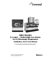
Installation, Use & Care Manual
This manual is updated as new information and models are released.
Visit our website for the latest manual. www.manitowocfsg.com
Leader in Ice & Beverage Dispensers
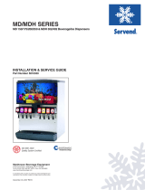
MDH-302/402
& icepic™ / Selectable Ice Series
Ice & Beverage Dispensers
Part Number 020003999 8/15

We reserve the right to make product improvements at any time.
Specifications and design are subject to change without notice.
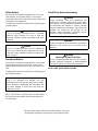
Safety Notices
As you work on Manitowoc equipment, be sure to pay
close attention to the safety notices in this manual.
Disregarding the notices may lead to serious injury and/
or damage to the equipment.
Throughout this manual, you will see the following types
of safety notices:
Procedural Notices
As you work on Manitowoc equipment, be sure to read
the procedural notices in this manual. These notices
supply helpful information which may assist you as you
work.
Throughout this manual, you will see the following types
of procedural notices:
NOTE: Text set off as a Note provides you with simple,
but useful, extra information about the procedure you
are performing.
Read These Before Proceeding:
NOTE: SAVE THESE INSTRUCTIONS.
! Warning
Text in a Warning box alerts you to a potential
personal injury situation. Be sure to read the
Warning statement before proceeding, and work
carefully.
!
Caution
Text in a Caution box alerts you to a situation in
which you could damage the equipment. Be sure to
read the Caution statement before proceeding, and
work carefully.
Important
Text in an Important box provides you with
information that may help you perform a procedure
more efficiently. Disregarding this information will
not cause damage or injury, but it may slow you
down as you work.
!
Caution
Proper installation, care and maintenance are
essential for maximum performance and trouble-
free operation of your Manitowoc equipment. Read
and understand this manual. It contains valuable
care and maintenance information. If you encounter
problems not covered by this manual, do not
proceed, contact Manitowoc Foodservice Group.
We will be happy to provide assistance.
Important
Routine adjustments and maintenance procedures
outlined in this manual are not covered by the
warranty.
! Warning
PERSONAL INJURY POTENTIAL
Do not operate equipment that has been misused,
abused, neglected, damaged, or altered/modified
from that of original manufactured specifications.

Part Number 020003999 8/15 1
Table of Contents
Section 1
General Information
Read This Manual. . . . . . . . . . . . . . . . . . . . . . . . . . . . . . . . . . . . . . . . . . . . . . . . . 1-1
Unit Inspection . . . . . . . . . . . . . . . . . . . . . . . . . . . . . . . . . . . . . . . . . . . . . . . . . . . 1-1
Model Numbers. . . . . . . . . . . . . . . . . . . . . . . . . . . . . . . . . . . . . . . . . . . . . . . . . . . 1-1
How to Read a Model Number . . . . . . . . . . . . . . . . . . . . . . . . . . . . . . . . . . 1-1
Accessories. . . . . . . . . . . . . . . . . . . . . . . . . . . . . . . . . . . . . . . . . . . . . . . . . . . . . . 1-1
Baffle for Manitowoc
®
Ice Machine . . . . . . . . . . . . . . . . . . . . . . . . . . . . . . . 1-1
Manual Fill Lid for Dispensers with an Ice Machine . . . . . . . . . . . . . . . . . . 1-1
Legs . . . . . . . . . . . . . . . . . . . . . . . . . . . . . . . . . . . . . . . . . . . . . . . . . . . . . . 1-2
Serial Number Location . . . . . . . . . . . . . . . . . . . . . . . . . . . . . . . . . . . . . . . . . . . . 1-2
Warranty Information . . . . . . . . . . . . . . . . . . . . . . . . . . . . . . . . . . . . . . . . . . . . . . 1-2
Section 2
Installation Instructions
General . . . . . . . . . . . . . . . . . . . . . . . . . . . . . . . . . . . . . . . . . . . . . . . . . . . . . . . . . 2-1
Dimensions . . . . . . . . . . . . . . . . . . . . . . . . . . . . . . . . . . . . . . . . . . . . . . . . . . . . . . 2-1
MDH-302 & 402 Footprint. . . . . . . . . . . . . . . . . . . . . . . . . . . . . . . . . . . . . . . . . . . 2-2
Location. . . . . . . . . . . . . . . . . . . . . . . . . . . . . . . . . . . . . . . . . . . . . . . . . . . . . . . . . 2-3
Location Requirements for Top Mounted Ice Machine Installations . . . . . . 2-3
Pre-installation Checklist. . . . . . . . . . . . . . . . . . . . . . . . . . . . . . . . . . . . . . . . . . . 2-4
Double Check . . . . . . . . . . . . . . . . . . . . . . . . . . . . . . . . . . . . . . . . . . . . . . . 2-5
Also Consider The Location Of The Following Items Before Installation . . 2-5
Additional Checks for Top Mounted Ice Machine Installations . . . . . . . . . . 2-5
Assembly. . . . . . . . . . . . . . . . . . . . . . . . . . . . . . . . . . . . . . . . . . . . . . . . . . . . . . . . 2-6
Installing Baffle for Ice Machine Installations . . . . . . . . . . . . . . . . . . . . . . . 2-6
Electrical . . . . . . . . . . . . . . . . . . . . . . . . . . . . . . . . . . . . . . . . . . . . . . . . . . . . . . . . 2-7
General . . . . . . . . . . . . . . . . . . . . . . . . . . . . . . . . . . . . . . . . . . . . . . . . . . . . 2-7
Minimum Circuit Ampacity . . . . . . . . . . . . . . . . . . . . . . . . . . . . . . . . . . . . . 2-7
Electrical Requirements . . . . . . . . . . . . . . . . . . . . . . . . . . . . . . . . . . . . . . . 2-7
Voltage . . . . . . . . . . . . . . . . . . . . . . . . . . . . . . . . . . . . . . . . . . . . . . . . . . . . 2-7
Minimum Circuit Amperage Chart . . . . . . . . . . . . . . . . . . . . . . . . . . . . . . . . 2-7
Grounding Instructions . . . . . . . . . . . . . . . . . . . . . . . . . . . . . . . . . . . . . . . . . . . . 2-7
Pump Deck Wiring . . . . . . . . . . . . . . . . . . . . . . . . . . . . . . . . . . . . . . . . . . . 2-8
Water Supply. . . . . . . . . . . . . . . . . . . . . . . . . . . . . . . . . . . . . . . . . . . . . . . . . . . . . 2-9
Recommended Plumbing . . . . . . . . . . . . . . . . . . . . . . . . . . . . . . . . . . . . . . 2-9
Diagram Location . . . . . . . . . . . . . . . . . . . . . . . . . . . . . . . . . . . . . . . . . . . . 2-9
MDH-302 12 Valve Plumbing Diagram . . . . . . . . . . . . . . . . . . . . . . . . . . . . 2-10
MDH-302 12 Valve Flex Manifold (1 per side) . . . . . . . . . . . . . . . . . . . . . . 2-10

Table of Contents (continued)
2 Part Number 020003999 8/15
MDH-402 16 Valve Plumbing Diagrams . . . . . . . . . . . . . . . . . . . . . . . . . . . 2-11
MDH-402 16 Valve Flex Manifold (1 per side) . . . . . . . . . . . . . . . . . . . . . . . 2-11
MDH-402 20 Valve Plumbing Diagram . . . . . . . . . . . . . . . . . . . . . . . . . . . . 2-12
MDH-402 20 Valve Flex Manifold (1 per side) . . . . . . . . . . . . . . . . . . . . . . . 2-12
CO2 System. . . . . . . . . . . . . . . . . . . . . . . . . . . . . . . . . . . . . . . . . . . . . . . . . . . . . . 2-13
Routing Internal Carb Tank Purge Tube . . . . . . . . . . . . . . . . . . . . . . . . . . . 2-13
Drains . . . . . . . . . . . . . . . . . . . . . . . . . . . . . . . . . . . . . . . . . . . . . . . . . . . . . 2-13
Step by Step Installation. . . . . . . . . . . . . . . . . . . . . . . . . . . . . . . . . . . . . . . . . . . . 2-14
General . . . . . . . . . . . . . . . . . . . . . . . . . . . . . . . . . . . . . . . . . . . . . . . . . . . . 2-14
Capacities . . . . . . . . . . . . . . . . . . . . . . . . . . . . . . . . . . . . . . . . . . . . . . . . . . 2-14
Specifications Chart . . . . . . . . . . . . . . . . . . . . . . . . . . . . . . . . . . . . . . . . . . . 2-14
Unit Installation . . . . . . . . . . . . . . . . . . . . . . . . . . . . . . . . . . . . . . . . . . . . . . 2-14
System Pressures . . . . . . . . . . . . . . . . . . . . . . . . . . . . . . . . . . . . . . . . . . . . 2-14
ADA Key Pads . . . . . . . . . . . . . . . . . . . . . . . . . . . . . . . . . . . . . . . . . . . . . . . 2-15
Starting Your Beverage System & Dispenser . . . . . . . . . . . . . . . . . . . . . . . 2-16
Section 3
Operation
General System Overview . . . . . . . . . . . . . . . . . . . . . . . . . . . . . . . . . . . . . . . . . . 3-1
MDH-302 Cold Carbonation System . . . . . . . . . . . . . . . . . . . . . . . . . . . . . . . . . . 3-2
MDH-402 Cold Carbonation System . . . . . . . . . . . . . . . . . . . . . . . . . . . . . . . . . . 3-3
Component Identification. . . . . . . . . . . . . . . . . . . . . . . . . . . . . . . . . . . . . . . . . . . 3-4
Sequence of Operation. . . . . . . . . . . . . . . . . . . . . . . . . . . . . . . . . . . . . . . . . . . . . 3-4
Ice Recommended for Dispensing . . . . . . . . . . . . . . . . . . . . . . . . . . . . . . . 3-4
Non-adjustable Agitation Timer . . . . . . . . . . . . . . . . . . . . . . . . . . . . . . . . . . 3-4
Ice Storage and Dispensing . . . . . . . . . . . . . . . . . . . . . . . . . . . . . . . . . . . . 3-5
Carbonation . . . . . . . . . . . . . . . . . . . . . . . . . . . . . . . . . . . . . . . . . . . . . . . . . 3-5
Syrup Delivery System . . . . . . . . . . . . . . . . . . . . . . . . . . . . . . . . . . . . . . . . . . . . . 3-6
B-I-B . . . . . . . . . . . . . . . . . . . . . . . . . . . . . . . . . . . . . . . . . . . . . . . . . . . . . . 3-7
Figal System . . . . . . . . . . . . . . . . . . . . . . . . . . . . . . . . . . . . . . . . . . . . . . . . 3-7
Operation Checks & Adjustments . . . . . . . . . . . . . . . . . . . . . . . . . . . . . . . . . . . . 3-8
Ice Delivery Switch Adjustment . . . . . . . . . . . . . . . . . . . . . . . . . . . . . . . . . . 3-8
Crushed or Cubed Default . . . . . . . . . . . . . . . . . . . . . . . . . . . . . . . . . . . . . . 3-8
Agitation Timer Operational Check . . . . . . . . . . . . . . . . . . . . . . . . . . . . . . . 3-8
Section 4
Maintenance
Cleaning. . . . . . . . . . . . . . . . . . . . . . . . . . . . . . . . . . . . . . . . . . . . . . . . . . . . . . . . . 4-1
Daily Cleaning . . . . . . . . . . . . . . . . . . . . . . . . . . . . . . . . . . . . . . . . . . . . . . . 4-1
Monthly Cleaning . . . . . . . . . . . . . . . . . . . . . . . . . . . . . . . . . . . . . . . . . . . . . 4-2
Cleaning Checklist . . . . . . . . . . . . . . . . . . . . . . . . . . . . . . . . . . . . . . . . . . . . 4-2

Table of Contents (continued)
Part Number 020003999 8/15
3
Preventive Maintenance. . . . . . . . . . . . . . . . . . . . . . . . . . . . . . . . . . . . . . . . . . . . 4-3
Disassembly . . . . . . . . . . . . . . . . . . . . . . . . . . . . . . . . . . . . . . . . . . . . . . . . . . . . . 4-3
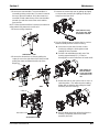
Disassembly for Cleaning and Maintenance . . . . . . . . . . . . . . . . . . . . . . . . 4-3
Disassemble the Rocking Chute . . . . . . . . . . . . . . . . . . . . . . . . . . . . . . . . . 4-4
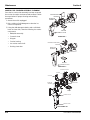
Disassemble the Ice Crusher Assembly . . . . . . . . . . . . . . . . . . . . . . . . . . . 4-4
Monthly Ice Crusher Assembly Cleaning . . . . . . . . . . . . . . . . . . . . . . . . . . 4-6
Reassemble the Ice Crusher Assembly . . . . . . . . . . . . . . . . . . . . . . . . . . . 4-7
Gear Motor Removal . . . . . . . . . . . . . . . . . . . . . . . . . . . . . . . . . . . . . . . . . . 4-8
Sanitizing. . . . . . . . . . . . . . . . . . . . . . . . . . . . . . . . . . . . . . . . . . . . . . . . . . . . . . . . 4-10
Beverage System Cleaning . . . . . . . . . . . . . . . . . . . . . . . . . . . . . . . . . . . . 4-10
Bag-In-Box System Sanitation . . . . . . . . . . . . . . . . . . . . . . . . . . . . . . . . . . 4-10
Figal Beverage System . . . . . . . . . . . . . . . . . . . . . . . . . . . . . . . . . . . . . . . . 4-11
Shipping, Storage and Relocation . . . . . . . . . . . . . . . . . . . . . . . . . . . . . . . . . . . 4-11
MDH Series Graphic Medallion Removal & Installation . . . . . . . . . . . . . . . . . . 4-12
Medallion Removal . . . . . . . . . . . . . . . . . . . . . . . . . . . . . . . . . . . . . . . . . . . 4-12
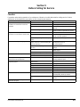
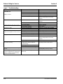
Section 5
Before Calling for Service
Checklist . . . . . . . . . . . . . . . . . . . . . . . . . . . . . . . . . . . . . . . . . . . . . . . . . . . . . . . . 5-1
icepic™ Troubleshooting. . . . . . . . . . . . . . . . . . . . . . . . . . . . . . . . . . . . . . . . . . . 5-2
Pump Troubleshooting. . . . . . . . . . . . . . . . . . . . . . . . . . . . . . . . . . . . . . . . . . . . . 5-3
Selectable Ice Troubleshooting. . . . . . . . . . . . . . . . . . . . . . . . . . . . . . . . . . . . . . 5-3
Drink Troubleshooting . . . . . . . . . . . . . . . . . . . . . . . . . . . . . . . . . . . . . . . . . . . . . 5-4
Liquid Level Control Troubleshooting . . . . . . . . . . . . . . . . . . . . . . . . . . . . . . . . 5-5


Part Number 020003999 8/15 1-1
Section 1
General Information
Read This Manual
Manitowoc Beverage Equipment (MBE) developed this
manual as a reference guide for the owner/operator and
installer of this equipment. Please read this manual
before installation or operation of the machine. A
qualified service technician must perform installation and
start-up of this equipment. Consult Section 5 within this
manual for service assistance.
If you cannot correct the service problem, call your MBE
Service Agent or Distributor. Always have your model
and serial number available when you call.
Your Service Agent ____________________________
Service Agent Telephone Number_________________
Your Local MBE Distributor ______________________
Distributor Telephone Number____________________
Model Number _______________________________
Serial Number ________________________________
Installation Date ______________________________
Unit Inspection
Thoroughly inspect the unit upon delivery. Immediately
report any damage that occurred during transportation to
the delivery carrier. Request a written inspection report
from a claims inspector to document any necessary
claim.
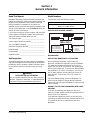
Model Numbers
This manual covers the following models:
HOW TO READ A MODEL NUMBER
Accessories
BAFFLE FOR MANITOWOC
®
ICE MACHINE
When installing a Manitowoc Ice Machine on a
dispenser, a baffle kit is required for proper installation.
The baffle kit is designed to prevent ice from lying
against the front of the ice machine, and melting down
the front of the dispenser. There are two different baffle
kits available for “S” series ice machines, one kit is for
the 30" wide machine, and the other kit is for the 22"
wide machine. There is also a kit for “Q” series ice
machines.
Kits are available through your local distributor. List
prices may be subject to change without notification.
Please call your local parts distributor for current pricing
before ordering.
MANUAL FILL LID FOR DISPENSERS WITH AN ICE
MACHINE
If you are top mounting your dispenser with an ice
machine, you will require a lid for the manual fill area at
the top, front of the dispenser.
If you ordered a dispenser and an ice machine at the
same time, the manual fill lid was included with the unit.
The manual fill lid can be ordered from your local
distributor.
! Warning
PERSONAL INJURY POTENTIAL
Do not operate equipment that has been misused,
abused, neglected, damaged, or altered/modified
from that of original manufactured specifications.
Beverage/Ice Dispensers
MDH-302, MDH-402, MDH-302 CI,
MDH-402 CI, MDH-402 SCI
S = Ice Only
SV = Ice/Beverage
NGF = Ice/Beverage
FRP = Ice/Beverage &
Integrated Flavor Shots
i = Intellicarb
CI = Ice Crusher
(icepic™)
SCI = Selectable
Crushed Ice
Ice Capacity
Model Prefix
Model Suffix
Model Base
MDH–302–i

General Information Section 1
1-2 Part Number 020003999 8/15
LEGS
Legs are optional equipment with most MBE dispensers.
Standard legs are 4" (10.2 cm) tall stainless steel legs. If
an ice machine is installed on top of the dispenser, legs
must not be installed. We do not recommend using legs
when an ice machine is mounted on the dispenser. The
combined weight of the dispenser, ice and ice machine
is more evenly distributed when the base area of the
dispenser is in contact with the countertop.
Serial Number Location
This number is required when requesting information
from your local distributor. The serial number is listed on
the SERIAL NUMBER DECAL affixed to the dispenser.
Serial Number Location
Warranty Information
Consult your local MBS Distributor for terms and
conditions of your warranty. Your warranty specifically
excludes all beverage valve brixing, general
adjustments, cleaning, accessories and related
servicing.
Your warranty card must be returned to MBS to activate
the warranty on this equipment. If a warranty card is not
returned, the warranty period can begin when the
equipment leaves the MBE factory.
No equipment may be returned to MBS without a written
Return Materials Authorization (RMA). Equipment
returned without an RMA will be refused at MBS’s dock
and returned to the sender at the sender’s expense.
Please contact your local MBS distributor for return
procedures.
Label

Part Number 020003999 8/15 2-1
Section 2
Installation Instructions
General
These instructions are provided to assist the qualified
installer. Contact your Manitowoc Beverage Equipment
Service Agent or call Manitowoc Beverage Equipment
for information regarding start-up services.
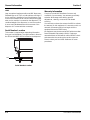
Dimensions
* Applies to icepic™ models also (MDH-302 CI & MDH-402 CI)
Important
Failure to follow these installation guidelines may
affect warranty coverage.
MODELABCDE
MDH-302* 42.75"
(108.59 cm)
30.50"
(77.47 cm)
22.50"
(57.15 cm)
38.75"
(98.43 cm)
20.50"
(52.07 cm)
MDH-402* 60.00"
(152.40 cm)
30.50"
(77.47 cm)
22.50"
(57.15 cm)
56.50"
(143.51 cm)
21.25"
(53.98 cm)
Coldplate Inlets
3/4" NPT
Fitting
Drain Pan
Front edge of drain pan
Coldplate Inlets
3/4" NPT
Fitting

Installation Instructions Section 2
2-2 Part Number 020003999 8/15
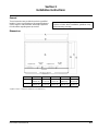
MDH-302 & 402 Footprint
Minimum Area
for Cutout
Maximum Area
for Cutout
D
C
B
A
* Applies to icepic™ models also (MDH-302 CI & MDH-402 CI)
Model
Maximum Minimum
ABCD
MDH-302* 38.75"
(98.43 cm)
20.50"
(52.07 cm)
3.00"
(7.62 cm)
32.00"
(81.28 cm)
MDH-402* 56.50"
(143.51 cm)
21.40"
(54.36 cm)
3.00"
(7.62 cm)
48.00"
(121.92 cm)
!
Caution
Cutting the countertop may decrease its strength.
Counter must be braced to support the dispenser
countertop weight plus ice storage capacity and
weight of ice machine, if applicable.

Section 2 Installation Instructions
Part Number 020003999 8/15 2-3
Location
The location selected for the beverage dispenser must
meet the following criteria. If any of these criteria are not
met, select another location.
• The air temperature must be at least 50°F (10°C), but
must not exceed 95°F (35°C).
• The location must not be near heat-generating
equipment or in direct sunlight and must be protected
from weather.
• The countertop must be level. Verify that the
countertop can support the weight of the dispenser,
or the dispenser/ice machine combination plus the
weight of the stored ice.
• Water lines, drains and power outlet must be within 6'
(1.8 m) of location.
LOCATION REQUIREMENTS FOR TOP MOUNTED
ICE MACHINE INSTALLATIONS
Location — Avoid placing the dispenser and/or ice
machine near heat sources such as radiators, ovens,
refrigeration equipment and direct sunlight.
Clearances — Refer to the ice machine installation
manual for clearances.
Front of ice machine to be flush with front of
dispenser — Some ice machines may overhang at the
back of the dispenser.
Drains — A separate drain line is required for the ice
machine, in addition to a drain line for the ice/beverage
dispenser.
Dispensers may require an adapter kit to install some
top-mounted ice machines. Contact your local distributor
for the correct adapter kit.
For full information about ice machine installation,
including clearances, plumbing lines, connections,
and electrical requirements, see the ice machine
installation manual.
!
Warning
Carbon Dioxide (CO
2
) displaces oxygen. Exposure
to a high concentration of CO
2
gas causes tremors,
which are followed rapidly by loss of consciousness
and suffocation. If a CO
2
gas leak is suspected,
particularly in a small area, immediately ventilate
the area before repairing the leak. CO
2
lines and
pumps must not be installed in an enclosed space.
An enclosed space can be a cooler or small room or
closet. This may include convenience stores with
glass door self serve coolers. If you suspect CO
2
may build up in an area, venting of the B-I-B pumps
and / or CO
2
monitors must be utilized.

Installation Instructions Section 2
2-4 Part Number 020003999 8/15
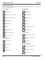
Pre-installation Checklist
When installing any system, first make sure the major components are available. Generally the major components
necessary for an installation are:
Pre-mix System:
B-I-B System also:
Post Mix System:
Figal System also:
Bulk Syrup System also:
CO
2
regulator set
Product connectors for Figal tank
Gas connectors for Figal tank
Beverage dispenser
Beverage tubing
CO
2
tank
Figal beverage tanks
Stepless (Oetiker) clamps
Chain for CO
2
tank
B-I-B connectors
B-I-B regulator set
B-I-B rack
B-I-B syrup boxes
CO
2
regulator set
Beverage dispenser
Beverage tubing
CO
2
tank
Carbonator
Stepless (Oetiker) clamps
Chain for CO
2
tank
Syrup connectors for Figal tank
Gas connectors for Figal tank
Figal syrup tanks
Syrup connectors for Bulk tank
Gas connectors for Bulk tank
Bulk syrup tanks

Section 2 Installation Instructions
Part Number 020003999 8/15 2-5
DOUBLE CHECK
ALSO CONSIDER THE LOCATION OF THE
FOLLOWING ITEMS BEFORE INSTALLATION
ADDITIONAL CHECKS FOR TOP MOUNTED ICE
MACHINE INSTALLATIONS
For full information about ice machine installation,
including plumbing line connections and electrical
requirements, see the ice machine installation
manual.
Do you have enough space to install the
dispenser or a dispenser and top mounted ice
machine?
Does top mounted ice machine (if utilized) have
a minimum of 6" (15.2 cm) clearance on all
sides?
Is the countertop level?
Can the countertop support the weight of the
dispenser, or the dispenser/ice machine
combination plus the weight of the stored ice?
Water line
Drain
Power outlet
Heating and air conditioning ducts
Location — Avoid placing the dispenser and/or
ice machine near heat sources such as
radiators, ovens, refrigeration equipment and
direct sunlight.
Clearances — 6" (15.2 cm) clearance on all
sides of the ice machine is needed.
Front of ice machine to be flush with front of
dispenser — The front of the ice machine must
be flush with the front of the dispenser. When
the ice machine is flush with the front of the
dispenser, some ice machines may overhang at
the back of the dispenser.
Drains — A separate drain line is required for
the ice machine, in addition to a drain line for
the ice/beverage dispenser.
Dispensers may require an adapter kit to install
some top-mounted ice machines. Contact your
local distributor for the correct adapter kit.
6" (15.2 cm)
clearance
for ice machine
ice machine
6"
(15.2 cm)
6"
(15.2 cm)
6" (15.2 cm)
6" (15.2 cm)

Installation Instructions Section 2
2-6 Part Number 020003999 8/15
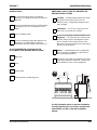
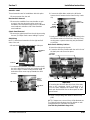
Assembly
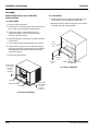
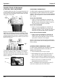
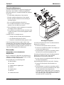
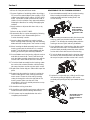
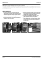
INSTALLING BAFFLE FOR ICE MACHINE
INSTALLATIONS
“S” Series Baffle
1. Remove both front panels.
2. Examine the ice machine to see if the machine has
four screws on the lower front plastic panels.
3. If there are screws, remove them from the
countersunk holes on the front surface of the
machine, save the screws.
4. Install the deflector, using the four screws removed
in step three.
5. Four screws and two backing plates are in the kit.
6. If there are no screws on the ice machine (step 2),
pierce the thin plastic countersunk holes, install the
backing plates and install the deflector using the
screws from the kit.
7. Replace the front panels.
“S” Series Ice Machine
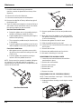
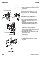
“Q” Series Baffle
1. Position baffle on top of water well with tab on the
front and the other tab inside the water well.
2. Mount the baffle on the left side of the ice machine
using the hole and screw provided.
“Q” Series Ice Machine
Backing Plate
to Be Inserted
into Side
Pocket of
Bulkhead
Screws
Screws
New Ice Baffle
Backing Plate
to Be Inserted
into Side
Pocket of
Bulkhead
Baffle, Manitowoc Ice Machine
Part #5007892
0.69"
(1.7 cm)
Ref.
6.32"
(16.0 cm)
Ref.
7.22"
(18.3 cm)
Ref.

Section 2 Installation Instructions
Part Number 020003999 8/15 2-7
Electrical
GENERAL
MINIMUM CIRCUIT AMPACITY
The minimum circuit ampacity is used to help select the wire
size of the electrical supply. (Minimum circuit ampacity is not
the beverage/ice machine’s running amp load.) The wire
size (or gauge) is also dependent upon location, materials
used, length of run, etc., so it must be determined by a
qualified electrician.
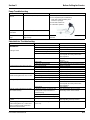
ELECTRICAL REQUIREMENTS
Refer to Ice Machine Model/Serial Plate for voltage/
amperage specifications.
VOLTAGE
The standard voltage for MDH Series dispensers is
120VAC - 60Hz. A power cord is provided with
120VAC - 60Hz models only. MDH Series dispensers
use a 1/7 hp gearmotor.
MINIMUM CIRCUIT AMPERAGE CHART
* Does not include carbonator motor.
Grounding Instructions
This appliance must be grounded. In the event of
malfunction or breakdown, grounding provides a path of
least resistance for electric current to reduce the risk of
electric shock. This appliance is equipped with a cord
having an equipment-grounding conductor and a
grounding plug. The plug must be plugged into an
appropriate outlet that is properly installed and grounded
in accordance with all local codes and ordinances.
! Warning
All wiring must conform to local, state and national
codes.
Important
Due to continuous improvements, this information is for
reference only. Please refer to the dispenser serial
number tag to verify electrical data. Serial tag
information overrides information listed on this page.
MDH-302/402
Dispensers
Voltage/Cycle
Minimum
Circuit Amps
With Standard or 24"
Extended Merchandiser
(Non-crusher)
120/60 4.50 *
220/60 2.25
34" Extended
Merchandiser
(Non-crusher)
120/60 5.00 *
220/60 2.50
With Standard or 24"
Extended Merchandiser
(with Crusher)
120/60 5.25 *
34" Extended
Merchandiser
(with Crusher)
120/60 5.75 *
!
Warning
Risk of electrical shock. Connect to a properly
grounded outlet only.
! Warning
Improper connection of the equipment-
grounding conductor can result in a risk of
electric shock. The conductor with insulation
having an outer surface that is green with or
without yellow stripes is the equipment
grounding conductor. If repair or replacement of
the cord or plug is necessary, do not connect
the equipment-grounding conductor to a live
terminal. Check with a qualified electrician or
serviceman if the grounding instructions are not
completely understood, or if in doubt as to
whether the appliance is properly grounded. Do
not modify the plug provided with the appliance
— if it will not fit the outlet, have a proper outlet
installed by a qualified electrician.

Installation Instructions Section 2
2-8 Part Number 020003999 8/15
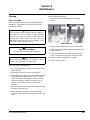
PUMP DECK WIRING
The supply cord is equipped with a three prong 5-15P.
When a Ground Fault Circuit Interrupter (GFCI) is
required by code, a breaker type protector must be
used. We do not recommend GFIC outlets as they are
known for more intermittent nuisance trips than panel
breakers. To ensure both the safety and proper
operation of this equipment, be certain that the electrical
receptacle is a proper design so as to accept this plug,
ensuring that the carbonator assembly is properly
grounded.
If the pump deck is to be installed in an area or
community whose local codes require permanent wiring,
the following procedure must be followed.
1. The three wires (white, black and green) must be fed
through the cable connector and brought into the
wiring compartment. The cable must be secured into
the connector.
2. The green wire from the cable must be connected to
the green screw that attaches to the inside panel of
the wiring compartment. Be sure to use a ring torque
terminal for connecting the wire to the screw.
3. The white wire from the cable must be joined to the
N terminal of the liquid level control board by a
suitable U.L. listed insulated cable connector.
4. The black wire from the cable must be joined to the
L1 terminal of the liquid level control board by a
suitable U.L. listed insulated cable connector.
!
Warning
When using electric appliances, basic precautions
should always be followed, including the following:
a. Read all the instructions before using the
appliance.
b. To reduce the risk of injury, close
supervision is necessary when an
appliance is used near children.
c. Do not contact moving parts.
d. Only use attachments recommended or
sold by the manufacturer.
e. Do not use outdoors.
f. For a cord-connected appliance, the
following shall be included:
• Do not unplug by pulling on cord. To
unplug, grasp the plug, not the cord.
• Unplug from outlet when not in use and
before servicing or cleaning.
• Do not operate any appliance with a
damaged cord or plug, or after the
appliance malfunctions or is dropped or
damaged in any manner. Contact the
nearest authorized service facility for
examination, repair, or electrical or
mechanical adjustment.
g. For a permanently connected appliance —
Turn the power switch to the off position
when the appliance is not in use and before
servicing or cleaning.
h. For an appliance with a replaceable lamp
— Always unplug before replacing the
lamp. Replace the bulb with the same type.
i. For a grounded appliance — Connect to a
properly grounded outlet only. See
Grounding Instructions.

Section 2 Installation Instructions
Part Number 020003999 8/15 2-9
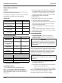
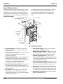
Water Supply
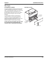
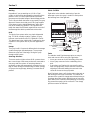
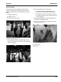
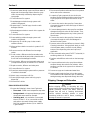
RECOMMENDED PLUMBING
The plumbing diagram is printed on a white vinyl label,
normally located above the inlet tubes for syrup and
water. The plumbing diagram label can be accessed by
removing the splash panel of the dispenser. The
plumbing diagram label explains which inlet coldplate
fittings supply which dispenser valves and water
manifolds.
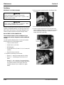
The water supply must first be connected to the
carbonator pump (not shown) before plumbing to
connection “A” shown on plumbing diagram. The
carbonator pump deck must be within 6' (1.8 m) of the
dispenser for optimum performance. See B-I-B
installation diagram for system pressure settings.
A check valve must be installed in the water supply
line 3' (0.9 m) from the noncarbonated water
connection “PW”. Contact factory if not installed.
DIAGRAM LOCATION
PLUMBING
DIAGRAM
PLUMBING
DIAGRAM
Splash Panel
Plumbing
Diagram
Plumbing
Diagram

Installation Instructions Section 2
2-10 Part Number 020003999 8/15
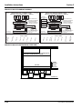
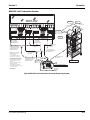
MDH-302 12 VALVE PLUMBING DIAGRAM
MDH-302 12 VALVE FLEX MANIFOLD (1 PER SIDE)
MDH-302 LEFT-HAND SIDE
SERVEND RECOMMENDED PLUMBING
2-1-1-2 FLEX
LEFT TO RIGHT
POST-CHILL
FLEX-MANIFOLD
PRE-CHILL
INLET LINES
* EXTERNALLY CARBONATED UNITS:
CARBONATOR IS REPLACED BY
A BY-PASS TUBE
NOTE: SYRUP LINES NOT SHOWN
NOTE: INTERNALLY CARBONATED UNITS - FROM CARBONATOR PUMP TO CARBONATOR LOCATED ON UNIT
EXTERNALLY CARBONATED UNITS - FROM EXTERNAL CARBONATOR TO MANIFOLD
PART
#5011802-0
C
ARB
WATER
(A)
SEE NOTE
PLAIN
WATER (C)
SYRU
P
#
8
SYRUP #9
SYRUP
#
10
SYRUP #11
S
YRUP #12
SYRUP #7
INTERNALLY CARBONATED UNITS:
A. PLAIN WATER TO THE CARBONATOR
B. CARB WATER FROM INTERNAL
CARBONATOR TO FLEX-MANIFOLD
C. PLAIN WATER TO FLEX-MANIFOLD
FOR ASSISTANCE
CALL (812) 246-7000
IN
OUT
INTERNAL
CARBONATOR
TANK
MDH-302 RIGHT-HAND SIDE
SERVEND RECOMMENDED PLUMBING
2-1-1-2 FLEX
LEFT TO RIGHT
POST-CHILL
FLEX-MANIFOLD
PRE-CHILL
INLET LINES
* EXTERNALLY CARBONATED UNITS:
CARBONATOR IS REPLACED BY
A BY-PASS TUBE
NOTE: SYRUP LINES NOT SHOWN
NOTE: INTERNALLY CARBONATED UNITS - FROM CARBONATOR PUMP TO CARBONATOR LOCATED ON UNIT
EXTERNALLY CARBONATED UNITS - FROM EXTERNAL CARBONATOR TO MANIFOLD
PART
#5011803-1
SYRUP #1
SYRUP #2
SYRUP #4
SYRUP #5
SYRUP #6
PLAIN WATER
(C)
CARB WATER (A)
SEE NOTE
SYRUP #3 -
VARIETY VLV
*OPTIONAL*
VARIETY VALVE ON #3
1-WATER
(THRU COLD PLATE)
4-SYRUP
(THRU COLD PLATE)
2-SYRUP
(AMBIENT)
3 -SYRUP
(AMBIENT)
INTERNALLY CARBONATED UNITS:
A. PLAIN WATER TO THE CARBONATOR
B. CARB WATER FROM INTERNAL
CARBONATOR TO FLEX-MANIFOLD
C. PLAIN WATER TO FLEX-MANIFOLD
FOR ASSISTANCE
CALL (812) 246-7000
IN
OUT
INTERNAL
CARBONATOR
TANK
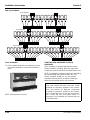
MANIFOLD TO CHANGE TO CARBONATED
OR NON-CARBONATED WATER
VALVES
CARB
WATER
5010331-2
5,6 4 3 1,2
PLAIN
WATER

Section 2 Installation Instructions
Part Number 020003999 8/15 2-11
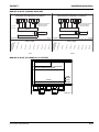
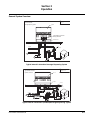
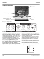
MDH-402 16 VALVE PLUMBING DIAGRAMS
MDH-402 16 VALVE FLEX MANIFOLD (1 PER SIDE)
COLD CARB MDH-402 16 VALVE
SERVEND RECOMMENDED PLUMBING
2-1-1-1-3 FLEX
LEFT TO RIGHT
MANIFOLD
CARBONATOR
COLDPLATE
MANIFOLD
CARBONATOR
COLDPLATE
INLET LINES
NOTE: SYRUP LINES NOT SHOWN
5010860-0
NOTE: SYRUP LINES NOT SHOWN
5010859-0
PLAIN WATER A
(TO CARBONATOR
FROM CARB PUMP)
PLAIN WATER A
(TO CARBONATOR
FROM CARB PUMP)
SYRUP #9
SYRUP #11
SYRUP #12
SYRUP #13
SYRUP #14
SYRUP #15
SYRUP #16
PLAIN WATER (B)
SYRUP #10
A. PLAIN WATER TO THE CARBONATOR
B. PLAIN WATER TO MANIFOLD
C. CARB WATER TO MANIFOLD
A. PLAIN WATER TO THE CARBONATOR
B. PLAIN WATER TO MANIFOLD
C. CARB WATER TO MANIFOLD
FOR ASSISTANCE
CALL (812) 246-7000
COLD CARB MDH-402 16 VALVE
SERVEND RECOMMENDED PLUMBING
INLET LINES
PLAIN WATER (B)
SYRUP #2
SYRUP #3
SYRUP #4
SYRUP #5
SYRUP #6
SYRUP #7
SYRUP #8
SYRUP #1
FOR ASSISTANCE
CALL (812) 246-7000
LEFT RIGHT
MANIFOLD TO CHANGE TO CARBONATED
OR NON-CARBONATED WATER
VALVES
CARB
WATER
5010131-2
67,8 5 4 1,2,3
PLAIN
WATER

Installation Instructions Section 2
2-12 Part Number 020003999 8/15
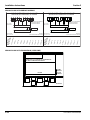
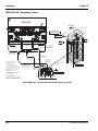
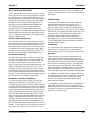
MDH-402 20 VALVE PLUMBING DIAGRAM
MDH-402 20 VALVE FLEX MANIFOLD (1 PER SIDE)
COLD CARB MDH-402 20 VALVE
SERVEND RECOMMENDED PLUMBING
3-1-2-1-3 FLEX
LEFT TO RIGHT
3-1-2-1-3 FLEX
LEFT TO RIGHT
MANIFOLD
CARBONATOR
COLDPLATE
MANIFOLD
CARBONATOR
COLDPLATE
INLET LINES
NOTE: SYRUP LINES NOT SHOWN
5010862-0
NOTE: SYRUP LINES NOT SHOWN
5010859-0
PLAIN WATER A
(TO CARBONATOR
FROM CARB PUMP)
PLAIN WATER A
(TO CARBONATOR
FROM CARB PUMP)
SYRUP #11
SYRUP #13
SYRUP #14
SYRUP #15
SYRUP #16
SYRUP #17
SYRUP #18
SYRUP #19
SYRUP #20
PLAIN WATER (B)
SYRUP #12
A. PLAIN WATER TO THE CARBONATOR
B. PLAIN WATER TO MANIFOLD
C. CARB WATER TO MANIFOLD
A. PLAIN WATER TO THE CARBONATOR
B. PLAIN WATER TO MANIFOLD
C. CARB WATER TO MANIFOLD
FOR ASSISTANCE
CALL (812) 246-7000
COLD CARB MDH-402 20 VALVE
SERVEND RECOMMENDED PLUMBING
INLET LINES
PLAIN WATER (B)
SYRUP #2
SYRUP #3
SYRUP #4
SYRUP #5
SYRUP #6
SYRUP #7
SYRUP #8
SYRUP #9
SYRUP #10
SYRUP #1
FOR ASSISTANCE
CALL (812) 246-7000
LEFT RIGHT
MANIFOLD TO CHANGE TO CARBONATED
OR NON-CARBONATED WATER
VALVES
CARB
WATER
5010676-0
78,9,10 5,6 4 1,2,3
PLAIN
WATER
Page is loading ...
Page is loading ...
Page is loading ...
Page is loading ...
Page is loading ...
Page is loading ...
Page is loading ...
Page is loading ...
Page is loading ...
Page is loading ...
Page is loading ...
Page is loading ...
Page is loading ...
Page is loading ...
Page is loading ...
Page is loading ...
Page is loading ...
Page is loading ...
Page is loading ...
Page is loading ...
Page is loading ...
Page is loading ...
Page is loading ...
Page is loading ...
Page is loading ...
Page is loading ...
Page is loading ...
Page is loading ...
Page is loading ...
Page is loading ...
Page is loading ...
Page is loading ...
-
 1
1
-
 2
2
-
 3
3
-
 4
4
-
 5
5
-
 6
6
-
 7
7
-
 8
8
-
 9
9
-
 10
10
-
 11
11
-
 12
12
-
 13
13
-
 14
14
-
 15
15
-
 16
16
-
 17
17
-
 18
18
-
 19
19
-
 20
20
-
 21
21
-
 22
22
-
 23
23
-
 24
24
-
 25
25
-
 26
26
-
 27
27
-
 28
28
-
 29
29
-
 30
30
-
 31
31
-
 32
32
-
 33
33
-
 34
34
-
 35
35
-
 36
36
-
 37
37
-
 38
38
-
 39
39
-
 40
40
-
 41
41
-
 42
42
-
 43
43
-
 44
44
-
 45
45
-
 46
46
-
 47
47
-
 48
48
-
 49
49
-
 50
50
-
 51
51
-
 52
52


MULTIPLEX MDH-302 & MDH-402 Icepic Selectable Ice Series 020003999020003999 Owner Instruction Manual
- Type
- Owner Instruction Manual
- This manual is also suitable for
Ask a question and I''ll find the answer in the document
Finding information in a document is now easier with AI
Related papers
-
MULTIPLEX M Series Owner Instruction Manual
-
-
-
-
-
-
-
-
-
Other documents
-
 Servend MDH-402 Series Troubleshooting guide
-
 IMI Cornelius, Inc. Vantage User manual
-
HQ W7-60561-BLN Datasheet
-
 Cornelius R-134A User manual
-
 Cornelius VANTAGE POST-MIX DISPENSER User manual
-
Manitowoc Ice Q Model Marine Dispenser Installation guide
-
 IMI Cornelius, Inc. VA13 Installation guide
-
GE GAF140SSNWW Dimensions Guide
-
 Cornelius Venture Installation guide
-
Manitowoc SU1024YC Troubleshooting guide


