Page is loading ...

Installation, Use & Care Manual
This manual is updated as new information and models are released.
Visit our website for the latest manual. www.manitowocfsg.com
Leader in Ice & Beverage Dispensers
VARIETY VALVES
for Servend Beverage Dispensers
Part Number 020004001 4/12

We reserve the right to make product improvements at any time.
Specifications and design are subject to change without notice.
Safety Notices
As you work on Manitowoc equipment, be sure to pay
close attention to the safety notices in this manual.
Disregarding the notices may lead to serious injury and/
or damage to the equipment.
Throughout this manual, you will see the following types
of safety notices:
Procedural Notices
As you work on Manitowoc equipment, be sure to read
the procedural notices in this manual. These notices
supply helpful information which may assist you as you
work.
Throughout this manual, you will see the following types
of procedural notices:
NOTE: Text set off as a Note provides you with simple,
but useful, extra information about the procedure you
are performing.
Read These Before Proceeding:
NOTE: SAVE THESE INSTRUCTIONS.
! Warning
Text in a Warning box alerts you to a potential
personal injury situation. Be sure to read the
Warning statement before proceeding, and work
carefully.
!
Caution
Text in a Caution box alerts you to a situation in
which you could damage the equipment. Be sure to
read the Caution statement before proceeding, and
work carefully.
Important
Text in an Important box provides you with
information that may help you perform a procedure
more efficiently. Disregarding this information will
not cause damage or injury, but it may slow you
down as you work.
!
Caution
Proper installation, care and maintenance are
essential for maximum performance and trouble-
free operation of your Manitowoc equipment. Read
and understand this manual. It contains valuable
care and maintenance information. If you encounter
problems not covered by this manual, do not
proceed, contact Manitowoc Foodservice Group.
We will be happy to provide assistance.
Important
Routine adjustments and maintenance procedures
outlined in this manual are not covered by the
warranty.
! Warning
PERSONAL INJURY POTENTIAL
Do not operate equipment that has been misused,
abused, neglected, damaged, or altered/modified
from that of original manufactured specifications.

Section 1
General Information
Read This Manual. . . . . . . . . . . . . . . . . . . . . . . . . . . . . . . . . . . . . . . . . . . . . . . . . 1-1
Unit Inspection . . . . . . . . . . . . . . . . . . . . . . . . . . . . . . . . . . . . . . . . . . . . . . . . . . . 1-1
Model Numbers. . . . . . . . . . . . . . . . . . . . . . . . . . . . . . . . . . . . . . . . . . . . . . . . . . . 1-1
How To Read A Model Number . . . . . . . . . . . . . . . . . . . . . . . . . . . . . . . . . 1-1
Serial Number Location . . . . . . . . . . . . . . . . . . . . . . . . . . . . . . . . . . . . . . . . . . . . 1-1
Warranty Information . . . . . . . . . . . . . . . . . . . . . . . . . . . . . . . . . . . . . . . . . . . . . . 1-2
Section 2
Installation Instructions
General . . . . . . . . . . . . . . . . . . . . . . . . . . . . . . . . . . . . . . . . . . . . . . . . . . . . . . . . . 2-1
Specifications . . . . . . . . . . . . . . . . . . . . . . . . . . . . . . . . . . . . . . . . . . . . . . . 2-1
Electrical . . . . . . . . . . . . . . . . . . . . . . . . . . . . . . . . . . . . . . . . . . . . . . . . . . . 2-2
Plumbing . . . . . . . . . . . . . . . . . . . . . . . . . . . . . . . . . . . . . . . . . . . . . . . . . . . 2-3
Retrofit Installation . . . . . . . . . . . . . . . . . . . . . . . . . . . . . . . . . . . . . . . . . . . 2-10
System Pressures . . . . . . . . . . . . . . . . . . . . . . . . . . . . . . . . . . . . . . . . . . . . 2-13
ADA Key Pads . . . . . . . . . . . . . . . . . . . . . . . . . . . . . . . . . . . . . . . . . . . . . . 2-14
Starting Your Beverage System & Dispenser . . . . . . . . . . . . . . . . . . . . . . . . . . 2-16
Section 3
Operation
General . . . . . . . . . . . . . . . . . . . . . . . . . . . . . . . . . . . . . . . . . . . . . . . . . . . . . . . . . 3-1
Sequence of Operation . . . . . . . . . . . . . . . . . . . . . . . . . . . . . . . . . . . . . . . . . . . . 3-2
Autofill . . . . . . . . . . . . . . . . . . . . . . . . . . . . . . . . . . . . . . . . . . . . . . . . . . . . . 3-2
Sanitary Lever . . . . . . . . . . . . . . . . . . . . . . . . . . . . . . . . . . . . . . . . . . . . . . . 3-2
Self-Serve . . . . . . . . . . . . . . . . . . . . . . . . . . . . . . . . . . . . . . . . . . . . . . . . . . 3-2
Portion Control . . . . . . . . . . . . . . . . . . . . . . . . . . . . . . . . . . . . . . . . . . . . . . 3-2
Programming the Portion Control Buttons . . . . . . . . . . . . . . . . . . . . . . . . . . . . 3-3
Restoring Factory Default Settings . . . . . . . . . . . . . . . . . . . . . . . . . . . . . . . 3-3
Section 4
Maintenance
Cleaning. . . . . . . . . . . . . . . . . . . . . . . . . . . . . . . . . . . . . . . . . . . . . . . . . . . . . . . . . 4-1
How To Replace The Front Cover . . . . . . . . . . . . . . . . . . . . . . . . . . . . . . . . . . . . 4-1
Mounting Block. . . . . . . . . . . . . . . . . . . . . . . . . . . . . . . . . . . . . . . . . . . . . . . . . . . 4-2
Removing A Valve . . . . . . . . . . . . . . . . . . . . . . . . . . . . . . . . . . . . . . . . . . . 4-2
Installing A Valve . . . . . . . . . . . . . . . . . . . . . . . . . . . . . . . . . . . . . . . . . . . . 4-2

Table of Contents (continued)
2 Part Number 020004001 4/12
Flow Controls . . . . . . . . . . . . . . . . . . . . . . . . . . . . . . . . . . . . . . . . . . . . . . . . . . . . 4-3
Change The Solenoid Or The Flow Control . . . . . . . . . . . . . . . . . . . . . . . . 4-3
Brixing . . . . . . . . . . . . . . . . . . . . . . . . . . . . . . . . . . . . . . . . . . . . . . . . . . . . . . . . . . 4-4
Brix Check . . . . . . . . . . . . . . . . . . . . . . . . . . . . . . . . . . . . . . . . . . . . . . . . . . 4-4
Brix Adjustment . . . . . . . . . . . . . . . . . . . . . . . . . . . . . . . . . . . . . . . . . . . . . . 4-5
Section 5
Before Calling for Service
Checklist . . . . . . . . . . . . . . . . . . . . . . . . . . . . . . . . . . . . . . . . . . . . . . . . . . . . . . . . 5-1

Section 1 General Information
Part Number 020004001 4/12 1-1
Section 1
General Information
Read This Manual
Manitowoc Beverage Equipment (MBE) developed this
manual as a reference guide for the owner/operator and
installer of this equipment. Please read this manual
before installation or operation of the machine. A
qualified service technician must perform installation and
start-up of this equipment, consult Section 5 within this
manual for service assistance.
If you cannot correct the service problem, call your MBE
Service Agent or Distributor. Always have your model
and serial number available when you call.
Your Service Agent ____________________________
Service Agent Telephone Number _________________
Your Local MBE Distributor ______________________
Distributor Telephone Number ____________________
Model Number _______________________________
Serial Number ________________________________
Installation Date ______________________________
Unit Inspection
Thoroughly inspect the unit upon delivery. Immediately
report any damage that occurred during transportation to
the delivery carrier. Request a written inspection report
from a claims inspector to document any necessary
claim.
Model Numbers
This manual covers the following models:
HOW TO READ A MODEL NUMBER
Serial Number Location
This number is required when requesting information
from your local distributor. The serial number is listed on
the SERIAL NUMBER DECAL affixed to the dispenser.
Serial Number Location
!
Warning
PERSONAL INJURY POTENTIAL
Do not operate equipment that has been misused,
abused, neglected, damaged, or altered/modified
from that of original manufactured specifications.
Beverage/Ice Dispensers
IC-2323, SV-150, SV-175, SV-200, SV-250, MDH-302, CEV-
30, CEV-40, CT-6, DI/DIL-2323
Variety Valves
AUTOFILL VALVE - 27-3102, SANITARY LEVER VALVE -
27-3105, PUSH BUTTON VALVE - 27-3104, PORTION
CONTROL VALVE - 27-3103
S = Ice Only
SV = Ice/Beverage
NGF = Ice/Beverage
FRP = Ice/Beverage &
Integrated Flavor Shots
i = Intellicarb
CI = Ice Crusher (IcePic)
SCI = Selectable
Crushed Ice
Ice Capacity
Model Prefix
Model Suffix
Model Base
MDH–302–i
Label

General Information Section 1
1-2
Part Number 020004001 4/12
Warranty Information
Consult your local MBE Distributor for terms and
conditions of your warranty. Your warranty specifically
excludes all beverage valve brixing, general
adjustments, cleaning, accessories and related
servicing.
Your warranty card must be returned to MBE to activate
the warranty on this equipment. If a warranty card is not
returned, the warranty period can begin when the
equipment leaves the MBE factory.
No equipment may be returned to MBE without a written
Return Materials Authorization (RMA). Equipment
returned without an RMA will be refused at MBE’s dock
and returned to the sender at the sender’s expense.
Please contact your local MBE distributor for return
procedures.

Part Number 020004001 4/12 2-1
Section 2
Installation Instructions
General
These instructions are provided to assist the qualified installer. Contact your Manitowoc Beverage Equipment Service
Agent or call Manitowoc Beverage Equipment for information regarding start-up services.
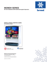
SPECIFICATIONS
Important
READ THIS BEFORE INSTALLATION
Failure to follow these installation guidelines may
affect warranty coverage.
Valve height 5.45 in (13.8 cm)
Valve width 2.50 in (6.4 cm)
Valve depth 5.72 in (14.5 cm)
Operating temperature range 32–140 °F (0–60 °C)
Operational relative humidity range 20–100%
Electrical rating 24 VAC
Static water pressure 40–60 psig
Static syrup pressure 60 psig
CO
2 pressure 70-75 psig
10.84 in
(27.5 cm)
5.45 in
(13.8 cm)
2.50 in
(6.4 cm)
5.72 in
(14.5 cm)

Installation Instructions Section 2
2-2
Part Number 020004001 4/12
ELECTRICAL
Grounding
• All fountain equipment with a Variety valve installed
must be properly grounded.
• The 24 VAC valve power supply must be properly
grounded.
Grounding The Dispenser For Autofill Variety Valves
For proper operation of the Autofill Variety valve, follow the steps below to determine if the existing Optifill valves need
to be grounded.
NOTE: These steps are usually only need to be followed on retrofit applications.
1. Turn on the power to the dispenser.
2. Disconnect the 24V power supply from an Optifill valve
adjacent to the Variety valve.
3. Check the voltage across the white wire of the
connector to the dispenser chassis. Check the voltage
across the black wire of the connector to the dispenser
chassis.
4. If the voltage across the white wire to the chassis is 24-
27 volts, the transformer is properly grounded. Proceed
with the Variety valve installation. If the voltage across
the black wire to the dispenser chassis is 24-27 volts,
reverse the load wires connected to the valve wire
harness as shown below and proceed with Variety valve
installation.
5. If the voltage across either the white or black wires to the
chassis is less than 24 volts, a grounding wire must be
installed on the transformer. Unplug the dispenser and
install the grounding wire on the transformer as shown
below.
6. After the grounding wire is installed, plug the dispenser
in and turn on the power. Recheck the voltage across
the white wire of the connector to the dispenser chassis
and across the black wire of the connector to the
dispenser chassis.
7. If the voltage across the white wire to the dispenser
chassis is 24-27 volts, proceed with the Variety valve
installation.
8. If the voltage across the black wire to the chassis is 24-
27 volts, reverse the load wires connected to the valve
wire harness and then proceed with Variety valve
installation.
9. After installing the Variety valve, check all valves to
make sure they all function properly.
!
Warning
Always unplug the power to the dispenser before making
changes to the electrical wiring in the dispenser.
Disconnect the hot load wire
(located below the black line wire).
Connect the hot load wire to
the piggyback connector on
the grounding wire.
Connect the grounding
wire 4 to the transformer.
Screw the grounding wire
to the chassis. (The
position or side of the
transformer may vary from
that shown here.)
NOTE: The appearance of
the transformer may vary
from that shown here.
GROUNDING
WIRE
TRANSFORMER
BRACKET
EXISITING
CHASIS SCREW
LOAD WIRE,
HOT
PIGGYBACK
CONNECTOR
LINE WIRE,
BLACK
LINE WIRE,
WHITE
LOAD WIRE,
NEUTRAL
TRANSFORMER
LOAD
REVERSE
CONNECTION
VALVE WIRE HARNESS

Section 2 Installation Instructions
Part Number 020004001 4/12 2-3
PLUMBING
Variety Valve Front View
90° Dole
FItting Long
1/4”Tubing
1/4” Tubing
Additional Non-
Chilled Syrup
90° Bend
1/4” x 1/4”
1/4” Tubing with
Insulation Plain Water,
From Cold Plate
90° Dole FItting
Short
Additional
Non-Chilled
Syrup
Plain Water,
From Cold
Plate
Chilled
Syrup, From
Cold Plate
Additional
Non-Chilled
Syrup
1/4” Tubing Additional
Non-Chilled Syrup
1/4” Tubing with
Insulation Chilled
Syrup, From
Cold Plate
90° Dole
FItting Long
1/4”Tubing
90° Bend
1/4” x 1/4”
90° Dole FItting
Short
Mounting Block
Front View Top View Key Pad
Syrup 1
Flow Control
Syrup 3
Water Syrup 2
Water
Flow Control
Water Solenoid
Red Wires
Syrup 1 Solenoid
Brown Wires
Syrup 3
Flow Control
Syrup 2
Flow Control
Syrup 2 Solenoid
Yello w Wires
Syrup 3 Solenoid
Blue Wires
Syrup 1
Syrup 3
Syrup 2
Syrup 1

Installation Instructions Section 2
2-4
Part Number 020004001 4/12
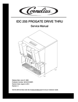
When Installing the Servend dispenser please follow the installation instructions supplied in the Installation and Service Guide.
Also follow the instructions below for finding and connecting the two ambient syrup lines for the Variety Valve.
Ambient Syrup Lines
1. Locate the two ¼” ambient syrup lines for Variety
Valve flavors #2 & #3. (See Figure 1)
2. Access the two ¼” ambient syrup lines by removing
the tie strap used to secure the lines to the unit.
3. Connect the syrup line that will be flavor #2 on the
Variety Valve to the ¼” ambient line marked #2.
Secure the connection with an Oetiker Clamp.
4. Connect the syrup line that will be flavor #3 on the
Variety Valve to the ¼” ambient line marked #3.
Secure the connection with an Oetiker Clamp.
NOTE: Please refer to the McCann’s Variety Valve
manual or contact McCann’s at 1-800-423-2429 for
more information about the following:
- Setting valve brix
- Programing the Portion Control Buttons
- Maintenance
- Service
Figure 1 (Flavor #2 & #3 Ambient Syrup Lines)

Section 2 Installation Instructions
Part Number 020004001 4/12 2-5
IC-2323 8 VALVE DIAGRAM
SV-150 6 VALVE DIAGRAM
RECOMMENDED PLUMBING IC2323
(WITH #6 VARIETY VALVE)
NOTES:
A. VALVES 1, 2, 7, 8 PERMANENTLY CARBONATED.
CONNECTED TO CARB WATER CIRCUIT.
B. PLAIN WATER TO FLEX MANIFOLD.
C. PLAIN WATER TO THE CARBONATOR.
D. CARB WATER TO COLDPLATE POST-CHILL.
VALVES 3, 4, 5, 6
PLUMBED TO THE FLEX MANIFOLD.
MANIFOLD : CHANGE TO CARBONATED OR
NON-CARBONATED WATER
1. ROTATE PLUNGER 180
O
USING A 5/32” ALLEN WRENCH
2. PULL PLUNGER UP TO GET NON-CARBONATED WATER
3. PUSH PLUNGER DOWN TO GET CARB WATER
4. TURN PLUNGER BACK 180
O
TO LOCK
SYRUP LINES 2 & 3 WILL CONNECT
TO BIB ON THE BACK OF THE UNIT
FLEX
MANIFOLD
NOT IN USE
FOR ASSISTANCE
CALL (812) 246-7000
5031148-0
1-SYRUP
(THRU COLD PLATE)
4-WATER
(THRU COLD PLATE)
FROM PUMP
POST-CHILL OUT
POST-CHILL
OUT
PLAIN WATER OUT
PLAIN WATER OUT
POST-CHILL IN
PRE-CHILL OUT
2-SYRUP
(AMBIENT)
3-SYRUP
(AMBIENT)
2-1-1-1-1-2 FLEX
RIGHT TO LEFT
PLUMBING: 2-1-1-2 MANIFOLDING
MANIFOLD : CHANGE TO CARBONATED OR
NON-CARBONATED WATER
1. ROTATE PLUNGER 180
O
USING A 5/32” ALLEN WRENCH
2. PULL PLUNGER UP TO GET NON-CARBONATED WATER
3. PUSH PLUNGER DOWN TO GET CARB WATER
4. TURN PLUNGER BACK 180
O
TO LOCK
5. PORT 5 IS NOT USED
*OPTIONAL*
VARIETY VALVE ON #3
INTERNAL CARBONATOR TANK
VALVES “SYRUP LINES NOT SHOWN”
* EXTERNALLY CARBONATED UNITS: CARBONATOR IS REPLACED BY A BY-PASS TUBE
FOR ASSISTANCE CALL (812) 246-7000
020000254-1
COLD PLATE
1-WATER
(THRU COLD PLATE)
4-SYRUP
(THRU COLD PLATE)
SYRUP #1
SYRUP #2
SYRUP #4
SYRUP #5
SYRUP #6
PLAIN WATER - FROM WATER SUPPLY
PLAIN WATER - FROM PUMP
TO CARBONATOR
SYRUP #3 - VARIETY VLV POSITION - 4
VALVES
CO
2
CIRCUITS
PRE-CHILL OUT TO CARBONATOR
CARBONATOR OUT TO POST-CHILL
2-SYRUP
(AMBIENT)
3 -SYRUP
(AMBIENT)

Installation Instructions Section 2
2-6
Part Number 020004001 4/12
SV 8 VALVE DIAGRAM
MDH-302 12 VALVE DIAGRAM
PLUMBING: 3-1-1-1-2 MANIFOLDING
*OPTIONAL*
VARIETY VALVE ON #4
INTERNAL CARBONATOR TANK (OPTIONAL)
VALVES “SYRUP LINES NOT SHOWN”
* EXTERNALLY CARBONATED UNITS: CARBONATOR IS REPLACED BY A BY-PASS TUBE
FOR ASSISTANCE CALL (812) 246-7000
5029871-2
COLD PLATE
1-WATER
(THRU COLD PLATE)
4-SYRUP
(THRU COLD PLATE)
SYRUP #1
SYRUP #2
SYRUP #4 - 4
SYRUP #3
SYRUP #5
SYRUP #6
SYRUP #7
SYRUP #8
PLAIN WATER - FROM WATER SUPPLY
PLAIN WATER - FROM PUMP
TO CARBONATOR
VALVES
CO
2
CIRCUITS
PRE-CHILL OUT TO CARBONATOR
CARBONATOR OUT TO POST-CHILL
2-SYRUP
(AMBIENT)
3 -SYRUP
(AMBIENT)
MDH-302 RIGHT HAND SIDE
SERVEND RECOMMENDED PLUMBING
2-1-1-2 FLEX
LEFT TO RIGHT
POST-CHILL
FLEX-MANIFOLD
PRE-CHILL
INLET LINES
* EXTERNALLY CARBONATED UNITS:
CARBONATOR IS REPLACED BY
A BY-PASS TUBE
NOTE: SYRUP LINES NOT SHOWN
NOTE: INTERNALLY CARBONATED UNITS - FROM CARBONATOR PUMP TO CARBONATOR LOCATED ON UNIT
EXTERNALLY CARBONATED UNITS - FROM EXTERNAL CARBONATOR TO MANIFOLD
PART
#5011803-1
SYRUP #1
SYRUP #2
SYRUP #4
SYRUP #5
SYRUP #6
PLAIN WATER
(C)
CARB WATER (A)
SEE NOTE
SYRUP #3 -
VARIETY VLV
*OPTIONAL*
VARIETY VALVE ON #3
1-WATER
(THRU COLD PLATE)
4-SYRUP
(THRU COLD PLATE)
2-SYRUP
(AMBIENT)
3 -SYRUP
(AMBIENT)
INTERNALLY CARBONATED UNITS:
A. PLAIN WATER TO THE CARBONATOR
B. CARB WATER FROM INTERNAL
CARBONATOR TO FLEX-MANIFOLD
C. PLAIN WATER TO FLEX-MANIFOLD
FOR ASSISTANCE
CALL (812) 246-7000
IN
OUT
INTERNAL
CARBONATOR
TANK

Section 2 Installation Instructions
Part Number 020004001 4/12 2-7
CEV-30 6 VALVE DIAGRAM
CEV-40 8 VALVE DIAGRAM
SERVEND RECOMMENDED PLUMBING
ALL INLETS ARE 3/8” BARBED FITTINGS EXCEPT CO
2
INLET
CEV-30i & CEV-30e
020001226-0
*OPTIONAL*
VARIETY VALVE ON #3
CHECK VALVE
(FLOW ARROW
POINTS INTO WATER LINE)
CARB
WATER
INLET
#3 AMBIENT
SYRUP ON
VARIETY VALVE
OPTION
CARB
WATER
INLET
#3 AMBIENT
SYRUP ON
VARIETY VALVE
OPTION
#2 AMBIENT
SYRUP ON
VARIETY VALVE
OPTION
#2 AMBIENT
SYRUP ON
VARIETY VALVE
OPTION
PLAIN WATER INLETPLAIN WATER INLET
VALVE #3
EXTERNAL CARBONATIONINTERNAL CARBONATION
VALVE #3
1-WATER
(SEE VALVE 3)
4-SYRUP
(THRU ICE BATH SEE VALVE 3)
2-SYRUP
(AMBIENT SEE VALVE 3)
3 -SYRUP
(AMBIENT SEE VALVE 3)
NOTES:
1. ALL VALVES ARE CARBONATED WATER AS SHIPPED FROM FACTORY
2. CHECK VALVE SUPPLIED WITH UNIT IS INSTALLED IN THE NON-CARBONATED WATER LINE INLET. THE FLOW DIRECTION ARROW SHOULD POINT INTO THE STAINLESS STEEL LINE
3. NUMBER 6 VALVE AWAYS CARBONATED
SYRUP 1
SYRUP 2
SYRUP 3
SYRUP 1
SYRUP 2
SYRUP 3
SYRUP 4
SYRUP 6
SYRUP 5
SYRUP 4
SYRUP 6
SYRUP 5
CO
2
INLET
SERVEND RECOMMENDED PLUMBING
ALL INLETS ARE 3/8” BARBED FITTINGS EXCEPT CO
2
INLET
CEV-40i & CEV-40e
020002740-0
VARIETY VALVE
BLOCK
CHECK VALVE
(FLOW ARROW
POINTS INTO WATER LINE)
#2-1
AMBIENT
SYRUP
#2-2
AMBIENT
SYRUP
#2-1
AMBIENT
SYRUP
#2-2
AMBIENT
SYRUP
#3-1
AMBIENT
SYRUP
#3-2
AMBIENT
SYRUP
#3-1
AMBIENT
SYRUP
#3-2
AMBIENT
SYRUP
NON-CARB WATER INLETNON-CARB WATER INLET
EXTERNAL CARBONATIONINTERNAL CARBONATION
VALVE #3VALVE #2
1-WATER
1-SYRUP
(#2-1 AMBIENT)
3-SYRUP
(THRU ICE BATH )
2 -SYRUP
(#2-2 AMBIENT)
1-WATER
1-SYRUP
(#3-1 AMBIENT)
3-SYRUP
(THRU ICE BATH )
2 -SYRUP
(#3-2 AMBIENT)
NOTES:
1. ALL VALVES ARE CARBONATED WATER AS SHIPPED FROM FACTORY
2. VALVE NUMBER 6 ,7, & 8 AWAYS CARBONATED
3. CHECK VALVE SUPPLIED WITH UNIT IS INSTALLED IN THE NON-CARBONATED WATER LINE INLET. THE FLOW DIRECTION ARROW SHOULD POINT INTO THE STAINLESS STEEL LINE
SYRUP 1
SYRUP 2
SYRUP 4
SYRUP 3
SYRUP 5
SYRUP 6
SYRUP 1
SYRUP 2
SYRUP 4
SYRUP 3
SYRUP 5
SYRUP 6
SYRUP 7
SYRUP 7
SYRUP 8
SYRUP 8
PLAIN WATER INLET
CARB WATER INLET
CO
2
INLET

Installation Instructions Section 2
2-8
Part Number 020004001 4/12
CT-6, 6 VALVE DIAGRAM
CT-6 RECOMMENDED PLUMBING
2-1-1-2 PLUMBING CONFIGUREATION
CT-6 WIRING DIAGRAM
COUNTER
TOP
VARIETY VALVE
BLOCK
W-WATER
(THRU COLD PLATE)
3-SYRUP
(#4-3 AMBIENT)
2-SYRUP
(#4-2 THRU COLD PLATE)
1-SYRUP
(#4-2 AMBIENT)
*OPTIONAL*
VARIETY VALVE
ON VALVE 4
020003552-0
SYRUP 1
SYRUP 2
SYRUP 3
SYRUP 4-1
SYRUP 4-2
SYRUP 4-3
SYRUP 5
SYRUP 6
UNIT DRAIN
CARB. OR PLAIN WATER 1 & 2
CARB. OR PLAIN WATER 3
CARB. OR PLAIN WATER 4
CARB. OR PLAIN WATER 5 & 6
LIGHTER MERCH.
POWER CORD
POWER CORD
ELECTRICAL BOX
VALVE JUMPER
HARNESS
CAUTION
ELECTRICAL SHOCK HAZARD
DISCONNECT POWER BEFORE SERVICING

Section 2 Installation Instructions
Part Number 020004001 4/12 2-9
DI/DIL-2323 8 VALVE POST-MIX PLUMBING & VARIETY VALVE
Install the beverage tubing to the appropriate fittings. Refer to the cold plate drawing on the front of the chest for your
individual set up.
MERCHANDISER
MERCHANDISER
POWER CORD
LEFT SIDE
CONDUIT
RIGHT SIDE
CONDUIT
CARB PUMP
MOTOR CORD
VARIETY VALVE
ABMIENT LINES
LINES
5-1 & 5-3
LINES
6-1 & 6-3
SERVEND RECOMMENDED PLUMBING DI/DIL-2323
OPTIONAL VARIETY VALVE
*OPTIONAL DUAL FLAVOR VALVE*
8A AMBIENT
8B THRU COLD PLATE
RELIEF VALVE
CARBONATOR
CO
2
TO
CARBONATOR
AMBIENT CARBONATION:
A. CARBONATED WATER
B. PLAIN WATER
INTERNALLY
CARBONATED
UNITS ONLY
INTERNAL CARBONATION:
A. PLAIN WATER TO CARBONATOR
FROM PUMP
B. PLAIN WATER (40-55 PSI) TO MANIFOLD
C. CARBONATED WATER FROM
CARBONATOR TO MANIFOLD
FOR ASSISTANCE
CALL (812) 246-7000
020001191-1
BOTTOM VIEW
3/4” NPT
DRAIN PAN
DRAIN
3/4” NPT
COLD PLATE
DRAIN
SYRUP 6
SYRUP 7
SYRUP 8 (B)
PLAIN WATER CIRCUIT (B)
CARBONATED WATER CIRCUIT (A)
SYRUP 5
SYRUP 4
SYRUP 3
SYRUP 2
WATER 7, 8
WATER 8
SYRUP 8 (B)
WATER 7
SYRUP 7
WATER 6
SYRUP 6
WATER 5
SYRUP 5
WATER 4
SYRUP 4
WATER 3
SYRUP 3
WATER 2
SYRUP 2
WATER 1
SYRUP 1
WATER 6
WATER 5
WATER 4
WATER 1, 2, 3
CO
2
IN
SYRUP 1
SYRUP 8 (A)
1-WATER
(THRU COLD PLATE)
2-SYRUP
(AMBIENT)
3-SYRUP
(AMBIENT)
4-SYRUP
(THRU COLD PLATE)
*OPTIONAL*
VARIETY VALVE
ON VALVE 6
Important
Before routing Variety Valve ambient lines through conduit you
must first route merchandiser power cord through conduit.
MERCHANDISER
MERCHANDISER
POWER CORD
VARIETY VALVE
ABMIENT LINES
CONDUIT
Single Variety Valve Dual Variety Valve

Installation Instructions Section 2
2-10
Part Number 020004001 4/12
RETROFIT INSTALLATION
The Variety valve may be retrofitted to nearly any soft-
plumbed fountain dispenser.
1. Inspect the Variety Valve
Thoroughly inspect the Variety valve upon delivery.
Immediately report any damage that occurred during
transportation to the delivery carrier. Request a written
inspection report from a claims inspector to document any
necessary claim. Make sure the following components are
available to install the valve:
*Size depends on tubing brand. Always use the
manufacturer’s recommended hose clamp size.
NOTE: A knockout tool is required for installation and is
not provided with the Variety valve.
2. Prepare the Site
A. Make sure the following equipment/supplies are
available before starting the installation:
B. Verify the plain water pressure is not too high or
too low.
• Too high—If the plain water pressure is ≥60 psig,
install a pressure regulator in the back room
where the plain water line branches out.
• Too low—Use one of the following methods to
check for low water pressure:
- Open the plain water valve and a carbonated
water valve at the same time. When the
carbonator pump turns on, read the pressure
gauge. If the pressure is <35 psig, a dedicated
plain water line is necessary.
- If a pressure gauge is not available, open the
existing plain water valve and note the amount
of water flowing. Open a carbonated water
valve until the carbonator pump turns on.
Check the plain water flow again. If the water
flow is greatly reduced, plan for a dedicated
plain water line from the back room to the
Variety valve.
C. Run new syrup lines from the back room to the
dispenser.
• If the existing syrup lines are underground and 2
extra lines are not available in the current tube
bundle, run a new tube bundle.
• If the existing syrup lines are in the ceiling, run 2
new lines beside the existing lines.
D. D. For carbonated water drink set up, check
access to carbonated water line or carbonator.
3. Remove the Existing Valve
A. Unplug the power supply to the unit.
B. Depressurize the water and syrup BIB. Flush all
lines of all syrup and water.
C. Gain access to the back of the mounting plate.
For drop-in dispensers, remove the splash plate.
For ice-drink units, remove the splash plate and
if needed, remove the ice chute.
Component Quantity
Variety valve 1
Mounting block 1
Retrofit plate kit 1
90° short dole fitting 2
90° long dole fitting 2
90° bends 2
Installation and service manual 1
3/8 in × 1/4 in splicer 2
Oetiker clamps (13.3 mm or 11.3 mm)* 8
Sheet metal screws 4
Component Quantity
BIB pumps (Shurflo pumps are
recommended)
2
BIB connectors 2
Space for 2 extra BIB bags or an additional
BIB rack
NOTE: Make sure that high
movers are placed on the lower
section of the rack.
3/8 in BIB tubing As needed
3/8 in standard beverage line for non-chilled
syrup (Bev-Ultra Seal)
As needed
1/4 in flexible tubing As needed
Socket wrench 1
1 1/8 in socket 1
Phillips screwdriver 1
Safety glasses 1
Alcohol wipes or rubbing alcohol As needed
Oetiker pliers 1
Tube cutter 1
UF-1 syrup separator 1
Pepsi brix cup 1
Food grade lubricant As needed
Knockout tool kit 1
!
Caution
Use safety glasses during the installation.

Section 2 Installation Instructions
Part Number 020004001 4/12 2-11
D. Remove the existing plain water valve and
mounting block from the dispenser. Remove 3
adjacent valves to provide more working space.
E. Remove the inlet water and syrup fittings from
the mounting plate. If the fittings are foamed in
place, remove the foam to access the fittings.
Push the 24 volt connector and wires to the
back of the mounting plate.
4. Install the Retrofit Mounting Plate
A. Apply the grease that is included in the tool kit to
the tip and the threads of the bolt and to the
sides and back of the punch before each use.
B. Load the knockout punch (cutting part) into the front
barrel die. Make sure the bolt is backed out enough
to allow the points of the knockout punch to be fully
enclosed in the front barrel die so that the front
barrel die will lay flush against the mounting plate.
C. Hold the rear support die behind the mounting plate
so that the 4 holes on the die are aligned with the
mounting plate holes. Make sure the label on each
piece of the knockout tool is facing up.
D. Place the front barrel die against the mounting
plate aligning the cap screws with the mounting
plate holes. Tighten each of the 4 cap screws
with the included hex key.
To ensure the cap screws are properly
tightened, tighten each cap screw until its head
bottoms out on the face of the front punch
barrel, and tighten an additional 1/2 turn.
Recheck the tightness of each cap screw, and
retighten if necessary.
E. Use a socket wrench to turn the bolt clockwise
until the knockout punch completely breaks
through the mounting plate.
F. Remove the entire knockout tool and dispose of
the piece punched out of the mounting plate.
NOTE: The actual position of the Variety valve on the unit may vary from that
shown in the illustration.
NOTE: Included but not shown: additional cap screws (4), hex key, grease
Knockout Tool Kit
Cap Screws
Bolt
Front
Barrel Die
Knockout
Punch
Rear
Support Die
A
B
Important
Make sure each of the 4 cap screws are securely
tightened prior to proceeding. If all 4 screws are not
tightened properly, the tool may not operate
correctly and damage to the tool may occur.
NOTE: Make sure the 24 volt
connector and wires are routed
through the wire chase on the front
barrel die.
SIDE VIEW
C
D
E

Installation Instructions Section 2
2-12
Part Number 020004001 4/12
5. Create New Lines
A. Use a 90° short fitting, 1/4 inch tubing, and
insulation from the existing PLAIN water line or
CARBONATED water line.
B. Create a new SYRUP LINE (Syrup #2) using a
90° short fitting and 1/4 inch tubing.
C. Create the CHILLED SYRUP LINE (Syrup #3)
using a 90° long fitting, 1/4 inch tubing, and the
insulation from existing chilled syrup line.
D. Create another new SYRUP LINE (Syrup #1)
using a 90° long fitting and 1/4 inch tubing.
6. Install the Mounting Block
A. Remove the front and rear covers from the
Variety valve. Remove the 4 screws from the
retrofit mounting plate.
B. Align all 4 inlet fittings with the mounting block
inlet holes. Use any food-grade lubricant on the
O-rings as needed.
C. Use the existing screws to tighten the mounting
block to the mounting plate. If the screws are not
long enough, use the screws provided in the
retrofit kit.
NOTE: Do not use the screws in the retrofit kit
on drop-in units.
7. Splice the Lines
A. Trim the length of the additional non-chilled
syrup lines as necessary to route the tubing
under the dispenser.
B. Use a 90° bend to route the tubing under the
dispenser.
C. Use 1/4 inch tubing to run the additional non-
chilled syrup lines to the respective 3/8 inch BIB
tubing. Trim the length of the 1/4 inch tubing as
necessary.
D. Use the 1/4 inch × 3/8 inch splicer to connect
the non-chilled syrup line to the BIB tubing.
E. Connect the water and chilled syrup lines to the
cold plate and trim the length as necessary.
!
Caution
Use safety glasses during the installation.
E
A
B
C
D
90° Long Fitting
90° Long Fitting
Oetiker Clamp
(13.3 mm)
REAR VIEW
SYRUP #3SYRUP #1
SYRUP #2
PLAIN OR
CARBONATED
WATER
A
B
C
D
Non-chilled Syrup Line From
Mounting Plate
Oetiker Clamp
1/4 inch Tubing

Section 2 Installation Instructions
Part Number 020004001 4/12 2-13
8. Install the Variety Valve
A. Align the Variety valve with the four mounting
block inlet holes and gently push the valve in
(toward the mounting block) until the back of the
valve is flush with the mounting block.
B. Hold the front of the valve and push up on the
bottom plate of the mounting block. You will hear
the locking sound on the mounting block. (This
is the same mounting method used with
standard UF-1 valves.)
C. Remount the remaining valves (those that were
removed to make working room). When all the
valves are in place, slowly pressurize the water
and syrup lines one at a time and make sure no
leaks occur.
D. Attach the 24 volt connector to the power supply.
Make sure the wires are placed inside the channel.
If the wires do not fit in the channel, trim the tab
enough to make the wires fit.
E. Brix the valve (see Valve Brix). Place the rear cover
on the valve. Make sure the ribbon cable is placed
behind the support on the rear valve cover.
F. Connect the ribbon cable on the front cover to the
ribbon cable on the valve and place the front cover
on the valve.
SYSTEM PRESSURES
Incoming tap water - must be at a minimum dynamic
pressure of 40 psi and maximum static pressure of 60 psi.
A
Mounting Block
Inlet Holes
D
Wire Channel
Tab
Ribbon
Cable
Important
The operating water pressure for the Variety Valve is 40-60
psig. If the incoming water pressure is not 40-60 psig,
adjust the water regulator. If a water regulator is not
installed, it is strongly recommended to install a water
regulator and, if necessary, a water booster system. The
operating syrup pressure for the Variety Valve is 60 psig
Important
Water boosters are preset to turn on at 65 psi and off
at 85 psi.
Operating
Pressure
Range

Installation Instructions Section 2
2-14
Part Number 020004001 4/12
ADA KEY PADS
These instructions are for installations with this option.
1. Remove power from the unit.
Merchandiser Removal
NOTE: Not necessary on CEV units, ADA connections
are made below the valve mount cap on these models.
2. Gain access to the merchandiser area of the dispenser
by one of the following methods;
A. MDH Series units, remove the medallion from
merchandiser to gain access to the area above
the valve mount cap. Medallions are removed
through the top of standard merchandisers and
either side of the extended merchandisers.
B. SV & SVi Series units, loosen the two knurled
fasteners located in the top of the merchandiser that
hold the merchandiser in place. Then remove the
merchandiser by lifting up and tilting forward.
Splash Panel Removal
3. Remove the splash panel from the unit by removing the
two (2) phillips head screws holding it in place. On CEV
units remove the drain pan to gain access to the two (2)
splash panel screws.
ADA Wiring
4. Route the ADA ribbon cable under the drain pan.
5. Continue routing the ADA cable up to the ADA harness;
A. CEV units, ADA harness is clipped to the wall of
the CEV below the valve mount cap.
B. SV & SVi units, continue routing the ADA cable
behind the valve mount cap on the left hand side of
the unit and connect to the ADA harness clipped
to the foam front.
C. MDH units locate the ADA harness, on units with a
crusher it will be on the left of the ice chute, non-
crusher units will be on the right. Connect to the
ADA harness that is clipped to the foam front.
6. Neatly tuck in and take up any slack remaining in the
ADA ribbon cable so it will not be in the way of any
moving parts or panels when they are placed back on
the unit.
NOTE: Units that also have ADA for beverage valves will
have 2 harness connections, one for the beverage ADA
Key Pad Box and one for the Variety Valve ADA Box.
The Variety Valve uses the smaller connector.
Drain Pan
ADA Ribbon
Cable
ADA Box
Internal ADA
Harness
ADA
Harness
ADA Box
Ribbon Cable
ADA Box
Ribbon
Connector
ADA
Harness
ADA Box
Ribbon
Connector
Valve
Mount Cap
Beverage
Valve ADA
Connector
Variety
Valve ADA
Connector
Harness
Clip
/