Page is loading ...

© 2021
Order #XXXXX
Locked layer contains
placeholder marks.
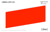
Top View
Perspective View
10’
10’
VK-1972 - 10’ x 10’ Inline
REV 12/2021
If you would like to tell us about your experience with your setup instructions please email us at [email protected]
SETUP INSTRUCTIONS

© 2021
Order #XXXXX
Locked layer contains
placeholder marks.
= 1 sq foot
Grid View

© 2021
Order #XXXXX
DO NOT USE POWER TOOLS
ALL CONNECTIONS MUST
BE TIGHTLY SECURED
Part Identification - Numbering
Spline Connection Base Plate & Extrusion Connection
General Setup Instructions
- Read entire setup instruction manual prior to
unpacking parts and pieces.
- The setup instructions are created specifically
for this configuration.
- Setup instructions are laid out sequentially in
steps, including exploded views with detailed
explanation for assembly.
WARNING
Cleaning & Packing
- For Cleaning Metal, Plex, & Laminate Parts:
Use a MILD NON-ABRASIVE cleanser and
soft cloth/paper towel to clean all surfaces.
- Keep exhibit components away from heat
and prolonged sun exposure.
Heat and UV exposure will warp and
fade components.
- Retain all provided Packing Materials.
All provided packing materials are for
ease of repacking & component protection.
Disassembly
- For loss prevention, tighten all set screws
and locks during disassembly.
7A
Hex Tool - Essential for Assembly
Extrusion & Lock Connection Engaged Lock
LADDERS OR LIFTS
MAY BE REQUIRED
General Information

© 2021
Order #XXXXX
Straight Connection
Adjust connectors if necessary to
prevent gaps in connection.
Upper Horizontal Extrusion
Lower Horizontal Extrusion
COMPLETED ASSEMBLY
3) Tighten all knobs to secure connection.
Slide verticals over
lower connectors.
Then slide upper
connectors into
groove of verticals.
Tighten all knobs.
When assembling frame, first attach all straight
connectors, then attach corner connectors.
1) Place extrusions end-to-end.
CEI152 Profile
Slide both connectors across seam of extrusions.
Tighten all knobs.
All knobs must be tightened securely to ensure a proper connection.
All knobs must be tightened securely to ensure a proper connection.
Corner
Connectors Corner
Connectors
Corner
Connectors Corner
Connectors
Straight Connector
Straight Connector
2) Loosen all knobs, then slide straight
connectors across the seam of extrusions.
Disassembly
1) Loosen all knobs.
2) Slide connectors off of one extrusion.
3) Tighten knobs to prevent loss during
packing & shipping.
Corner Connection
3) Tighten all knobs to secure connection.
Disassembly
1) Loosen knobs on vertical extrusions.
2) Slide the vertical extrusions off of
corner connectors on lower and upper
horizontal extrusions.
1) Loosen knobs, then slide vertical extrusions onto
corner connectors of lower horizontal extrusion.
2) Slide corner connectors of upper horizontal
extrusion into grooves of vertical extrusions.
Keep straight connectors in groove of
extrusion. Do not remove connectors
during disassembly.
CEI152 Frame Assembly

© 2021
Order #XXXXX
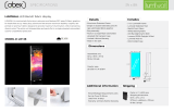
Graphic Removal
To remove the graphic
the frame, locate the fabric
pull tab. Gently pull up on the
tab to remove the fabric.
Step 1
Insert corner A. Turn edge of
graphic so silicon welt is
perpendicular to face of
graphic. Insert narrow side
of welt with fabric to outside
into the channel. Repeat for
other side of this corner.
Step 2
Repeat Step 1 for opposite
corner C, then insert corner
B, followed by corner D, to
complete the installation of
the corners.
Step 3
Once all corners are inserted,
press one silicon edge into
channel from corners and
work toward the center.
Make sure welt is fully inserted
into channel. Continue until
all sides are done. Smooth
out edges of graphic.
It is important to first insert
graphic into each alternate
corner then to the sides of
the frame. If this is not done,
graphic will not fit into the
frame correctly.
Corner A
Corner D
Corner B
Corner C
from
SEG Installation

© 2021
Case 1 of 2
Order #XXXXX
Locked layer contains
placeholder marks.
Top View of Each Level
Graphics
Setup Hardware
Level 1
(Bottom level)
Level 2 Level 3
6,6
1
1A 3A 2A2 3
6A,6A
Case Packing

© 2021
Case 2 of 2
Order #XXXXX
Locked layer contains
placeholder marks.
Top View of Each Level
Level 1
(Bottom level)
Level 2 Level 3
Monitor
Mount
7 7 4A 5A 4 5
Case Packing

© 2021
Step 1 of 1
Order #XXXXX
Locked layer contains
placeholder marks.
Completed Assembly
Item
1,1A
2,2A
3,3A
4,4A
5,5A
6,6A
7
Qty.
1,1
1,1
1,1
1,1
1,1
2,2
2
Description
38” CEI152 Horizontal Extrusion
38” CEI152 Horizontal Extrusion
38” CEI152 Horizontal Extrusion
47.5” CEI152 Vertical Extrusion
47.5” CEI152 Vertical Extrusion
45.677” Z45 Vertical Extrusion
Base Plate
Steps:
1) Assemble CEI152 extrusions together, flat on floor. See CEI152 Frame Assembly
sheet, for instruction.
2) Connect extrusions [6] and [6A] together. See Z45 Straight Connection detail.
3) Attach [6/6A] assemblies into assembled CEI152 frame. See Z45 Attachment detail.
4) Attach base plates to [1/4] and [3/4A]. See Base Plate Attachment detail.
5) Install SEG graphic to front and blocker fabric to back of assembled frame.
See SEG Graphic Installation sheet for instruction.
6) Attach monitor mount to extrusions [6A]. See Monitor Mount Attachment detail.
*
**
*
*
123
1A
5
4
5A
4A
6A
6
7
7
6A
6
2A 3A
*
Base
Plate
Bolt
Fixed Bolt
Bolt
Vertical
Extrusion
Horizontal
Extrusion
Base Plate Attachment
Place key hole over fixed bolt on
assembled frame, then slide down.
Secure with bolts, washer, and wing nut.
Washer
Wing Nut
Key Hole
Z45 Straight Connection
*
PR53
Connector
Z45 Z45
Insert connector into extrusions.
Secure with set screws.
Set Screw
To prevent product loss, keep all
screws attached to connector
after disassembling.
Keep connectors attached to [6], when packing.
CEI-152
Z45
Z45 Attachment
Attach Z45 vertical to middle
groove of CEI-152 horizontal.
*
F
r
o
n
t
o
f
F
r
a
me
**
**
Vertical Extrusion
Monitor
Mount
Standoff
Screw standoffs into vertical extrusions. Attach
monitor mount to standoffs, using caps
Standoffs attach through SEG graphic.
*Monitor Mount Attachment
Cap
SEG Graphic
Backwall Assembly
/