Page is loading ...

SPECIFICATIONS / ASSEMBLY
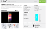
ELITE GRAPHIC WALL fabric display
ELITE GRAPHIC WALL is constructed of aluminum extrusion
and features SEG press fit fabric graphics for hassle free set up.
Heavy duty aluminum feet ensure maximum stability. Graphics
are printed on premium fabric for vibrant colors. The entire unit
disassembles and packs flat in a single rotomolded case for
unparalleled protection.
Details
Set-Up Time: 45-50min
Lead Time: 10 Days
Warranty: Limited Lifetime Warranty
Dimensions
Additional information
Shipping
Includes
• 10’ x 8’ Elite Frame
• Elite Stabilizer Feet
• SEG Front Fabric Graphic
• Elite Tool Kit
• Rotomolded Case
Assembled unit:
120”w x 95.25”h x 17.5”d
2413mm x 3048mm x 444mm
55 lbs / 25 kgS
Graphic area:
119.5”w x 94.5”h
3035mm x 2400mm
• 1.5” Low-profile aluminum extrusion
frame
• Single or double-sided SEG press fit
dye-sublimated fabric graphics
• Easy assembly
• Packs in a single rotomolded
flat transport case
• Limited Lifetime Warranty
• Made in the USA
Packs in ( 1 ) L-8R1851-02 case
Shipping dimensions:
51”h x 18”w x 4.5”d
1295mm x 457mm x 114mm
85 lbs / 38.6 kgS
3D VIEW
MODEL #: EGW-108
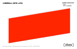
FRONT VIEW
RIGHT VIEW
PR INTE D FABRIC
119.5"W x 94.5"H
95"
120"
17 1/2"
95 1/4"

ASSEMBLY / INSTRUCTIONS
10ft.x 8ft
1.
Secure base plate
to bottom horizontal
extrusions with provided
bolt and wing nut
Insert the silicon
edge of the fabric
into the groove of
the extrusions.
Start on the corners,
then centers and work
your way to corners from
center on both directions.
To pull fabric graphic out
of extrusion groove, use
pull tab on corner
3. GRAPHIC
2.
5. WALL MOUNT
(Optional)
Attach wall bracket
to top extrusion
groove with provided
hammerhead screw.
Locate position of wall
bracket on extrusion
(preferably by wood stud) by sliding the
bracket on the extrusion and tighten it.
Secure the frame to the wall with provided
wood screw.
PACKING DIAGRAM
EGW-108 PACKAGE CONTENTS
Abex Exhibit Systems • 355 Parkside Drive, San Fernando, CA 91340 • (800) 537-0231
Extrusion fabric groove
fabric graphic
w/silicon edge
4. LIGHT ASSEMBLY
(Optional)
Slide light clip into the light.
Then place the light into the
groove and gently lower it down
Connect frame extrusions together, as shown, using
Torx tool (included). Do not overtighten.
NOTE: Remove corner connectors
from exrtrusions before packing.
NOTE: Remove connectors
from beams before packing
Connect frame spliced extrusions together, as shown,
using Torx tool (included). Do not overtighten.
Connect frame spliced extrusions together, as shown,
using Torx tool (included). Do not overtighten.
Place tension lock into groove. Insert Torx 30
wrench and turn 1/2 turn.
1. Slide straight connector (Z967) into inner
channel of extrusion.Turn screw enough to hold
connector in place.
2. Take another extrusion and slide onto straight
connector. Tigthen both screws to connect
extrusions together.
3. Repeat above steps to connect all spliced
extrusions together.
4. Slide corner connector (Z966) into both sides of
horizontal extrusions.Turn each screw enough to
hold connector in place.
6. Slide vertical extrusions onto corner connectors
of top horizontal extrusion. Turn each screw
enough to hold connector in place.
7. Finish frame assembly by sliding corner
connectors of bottom horizontal extrusion into
inner
channel of vertical extrusions and tighten the
screws to secure frame extrusions together.
M1307 40" (1016MM) EXTRUSION W/ (1) 45° CUT
Profile Label
001
Description
1/4" ALUMINIUM OVAL BASE PLATE 17.5" (444.5MM) x 3.15" (80MM)
#
3
002
003
M1307 40" (1016MM) EXTRUSION W/ (1) 45° CUT & (1) HOLE FOR BASE PLATE
1
1
2
M1307 47.5" (1206.5MM) EXTRUSION W/ (1) 45° CUT
004
1
2
M1307 40" (1016MM) EXTRUSION W/ (1) HOLE FOR BASE PLATE
005
006 M1307 47.5" (1206.5MM) EXTRUSION W/ (1) 45° CUT
1
2
4
1
008
007 1
M1307 40" (1016MM) EXTRUSION W/ (1) 45° CUT & (1) HOLE FOR BASE PLATE
4 Z966 90° CORNER INTERNAL CONNECTOR
5/16-18 FLAT HEAD SCREW 2.25" LONG W/ WASHER & WING NUT3
1 119.5"W (3035MM) x 94.5"H (2400MM) SINGLE SIDED DYESUB GRAPHIC W/ SEG WELT ALL 4 SIDES
8 Z967 STRAIGHT INTERNAL CONNECTOR
Z4400 45.9" (1165.9MM) EXTRUSION W/ (1) TENSION LOCK
M1307 40" (1016MM) EXTRUSION
009
010
011
M1307 40" (1016MM) EXTRUSION W/ (1) 45° CUT
Z4400 30.2" (767MM) EXTRUSION W/ (1) TENSION LOCK
001
001
002
003
004
005
006
Tension Lock
Torx Tool
008
007
001
009
006
005
010
010
010
010
011
011
NOTE: Remove connectors from
extrusions before packing

UNIT SIZES
3ft, 4ft, 6ft, 8ft & 10ft. Widths
10x8 8x8 6x8 6x6
4x8 4x6 4x4 3x8
3x6 3x4 3x3
/