Page is loading ...

SPECIFICATIONS 3ft x 8ft
Assembled unit:
36”w x 95”h x 17.5”d
55 lbs / 25 kgS
Graphic area:
35 13/16”w x 94 13/16”h
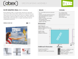
LUMIWALL LED Backlit fabric display
LUMIWALL is constructed of aluminum extrusion and features SEG press fit fabric graphics
for hassle free set up. Heavy duty aluminum feet ensure maximum stability. Graphics are
printed on premium fabric designed to provide maximum illumination while maintaining
vibrant colors. The entire unit disassembles and packs flat in a single wheeled rotomolded
case for unparalleled protection.
Details
Power/Wattage Requirements: 40w
Set-Up Time: 25-30min
Lead Time: 10 Days
Warranty: Limited Lifetime Warranty
Additional information
Shipping
Includes
• 3’ x 8’ Lumiwall Frame
• Lumiwall Stabilizer Feet
• Backlit Front Fabric
• White Backing Fabric
• LED Backlighting Kit (800
Lumens, 6500k Daylight White)
• Lumiwall Tool Kit
• Rotomolded Case
• Aluminum Extrusion Frame
• Single or double-sided SEG press fit
dye-sublimated fabric graphics
• Easy assembly
• Packs in a single 4825 rotomolded
wheeled, flat transport case
• Limited Lifetime Warranty
• Made in the USA
Packs in ( 1 ) 4825 case
Shipping dimensions:
50”h x 27”w x 7”d
1270mm x 685mm x 178mm
55 lbs / 25 kgS
3D VIEW
MODEL #: LW-38
Dimensions
FRONT VIEW
RIGHT VIEW
95 13/16"
36 13/16"
95”
17 1/2"
12 1/4"
BACKLIT FABRIC
35 13/16” x 94 13/16”

1.
Insert the silicon
edge of the fabric
into the groove of
the extrusions.
Start on the corners,
then centers and work
your way to corners from
center on both directions.
To pull fabric graphic out
of extrusion groove, use
pull tab on corner
2. GRAPHIC
4. WALL MOUNT
(Optional)
Attach wall bracket
to top extrusion
groove with provided
hammerhead screw.
Locate position of wall
bracket on extrusion
(preferably by wood stud) by sliding the
bracket on the extrusion and tighten it.
Secure the frame to the wall with provided
wood screw.
LW-38 PACKAGE CONTENTS
Extrusion fabric groove
fabric graphic
w/silicon edge
1. Slide straight connector (Z967) into inner
channel of extrusion.Turn screw enough to hold
connector in place.
2. Take another extrusion and slide onto straight
connector. Tigthen both screws to connect
extrusions together.
3. Repeat above steps to connect all spliced
extrusions together.
4. Slide corner connector (Z966) into both sides of
horizontal extrusions.Turn each screw enough to
hold connector in place.
6. Slide vertical extrusions onto corner connectors
of top horizontal extrusion. Turn each screw
enough to hold connector in place.
7. Finish frame assembly by sliding corner
connectors of bottom horizontal extrusion into
inner channel of vertical extrusions and tighten
the screws to secure frame extrusions together.
Connect frame extrusions together, as shown, using
Torx tool (included). Do not overtighten.
NOTE: Remove corner connectors
from exrtrusions before packing.
Connect frame spliced extrusions together, as shown,
using Torx tool (included). Do not overtighten.
NOTE: Remove connectors from
extrusions before packing
Tighten both screw firmly.
Loosen the screws on base plate but
do not remove them. Than swivel
base plates.
Bottom view
Bottom view
3. LIGHT ASSEMBLY
Lights come attached to extrusions. Ensure all lighting strips are connected. Once frame is assembled,
connect strip-to-power cords to the end of top and bottom lights chain.
- For bottom lights connect strip-to-power cord to power supply directly.
- For top lights connect extension cord to strip-to-power cord and run with wire managment extrusion then
connect to power supply.
Run AC power cord out through grommet hole on vertical upright and connect to power outlet.
To remove or re-attach light strips use provided thumbscrews with plate
Strip-To-Power Cord
EXtension Cord 12ft
PACKING DIAGRAM
INSTRUCTIONS / ASSEMBLY
ABEX EXHIBITS • ABEX.COM • 355 PARKSID E DR. SAN FERNANDO, CA 91340 • (800) 537 -0231
3ft x 8ft
001
001
002
003
005
004
Z965 - Corner Connector (2)
006
007
Power Supply
Wire Managment Hole
Z967 - Straight Connector (2)
008
Profile Label
001
Description
1/4" ALUMINIUM OVAL BASE PLATE 17.5" (444.5MM) x 4.72" (120MM)
#
2
002
003
M1901 36" (914.4MM) EXTRUSION W/ (2) 45° CUTS, (4) HOLES FOR BASE PLATE & LIGHTS
M1901 47.5" (1206.5MM) EXTRUSION W/ (1) 45° CUT
1
1
004
M1901 47.5" (1206.5MM) EXTRUSION W/ (1) 45° CUT, PLASTIC EXTR. & POWER SUPPLY
1
005
M1901 36" (914.4MM) EXTRUSION W/ (2) 45° CUTS & LIGHTS
1
8 Z966 90° CORNER INTERNAL CONNECTOR
5/16-18 FLAT HEAD SCREW 0.75" LONG FOR BASE PLATES
4
2 35.5"W (908MM) x 94.5"H (2400MM) SINGLE SIDED DYESUB GRAPHIC W/ SEG WELT ALL 4 SIDES
M1901 47.5" (1206.5MM) EXTRUSION W/ (1) 45° CUT
006
1 M1901 47.5" (1206.5MM) EXTRUSION W/ (1) 45° CUT & PLASTIC EXTR.
007
1
4 Z967 STRAIGHT INTERNAL CONNECTOR
Z4400 34.75" (882.7MM) EXTRUSION W/ (2) LOCKS
008
1

10x8 8x8 6x8 6x6
4x8 4x6 4x4 3x8
3x6 3x4 3x3
UNIT SIZES - 3FT, 4FT, 6FT, 8FT & 10FT WIDTHS
/