Page is loading ...

Connection to the electrical system
(To be carried out by an authorized electrician)
When making the connections on site, run the power
supply cable to the control box across an external high
voltage switch and through the cable gland fitted in the
casing. The control box is protected by an internal 2A
fuse.
The pump(s) supplied is/are always wired for 3 x 400
V. The pump motors have degree of protection S 33 (IP
44) and class B insulation.
Table 2.
Number of pumps
EUQA Size/
Humidification rate
20-42, 50, 51 60%-90% 1 –
44, 52, 53, 60 60%-90% – 1
62, 71, 80 60% 1 –
62, 71, 80 90% – 1
64, 73 60%-90% 2 –
82, 84 60% 2 –
82, 84 90% – 2
Connection to the water system
The water supply is controlled by a built-in solenoid
valve. Connect the supply pipe to the inlet branch. Fit a
shut-off valve, Item 2, in the water supply pipe.
Table 1. Connection sizes
To avoid clogging, fit a water filter, Item 3 (with a max.
mesh of 500 µm) between the shut-off valve and the
humidifier.
Connect the drain pipe, Item 5, to the humidifier drain
connection. The drain should be fitted with a cleanable
water trap, Item 4, and should run, without reduction
in diameter, to a floor gulley. On size 44 and 52 through
84 units, two water traps coupled in parallel should be
used.
The shut-off valve, water trap and water filter are not
included in the delivery.
EUQA Humidifier, for circulated water
Fläkt Woods 8273 GB 2007.06 1 We reserve the right to alter specifications.
EU Air handling unit INSTALLATION/MAINTENANCE
17
3
2
44
16
15
14
1
9
7
8
10
11 12
13
5
5
6
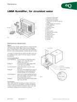
1. Control box, external
2. Shut-off valve (not included)
3. Water filter, with a max mesh
of 500 µm (not included)
4. EUAZ-08 Water trap (acces-
sory)
5. Drain pipe
6. Humidifier fill
7. Droplet eliminator
8. Spray pipes
9. Pump
10. Flow controller
11. Valve with motor actuator
12. Overflow hose
13. Level sensor
14. Solenoid valve
15. Flushing hose
16. End plug
17. Spacer plate
Size 20–42, 50, 51
Size 44, 52,
53–84
Fig. 1
Connection number/Diameter
Size Supply connection/ Drain connection
(male threads)
20-42, 50, 51 No. 15 R 1/2" No. 32, R 1 1/4"
female threads
44, 52-84 No. 20, R 3/4" 2 drains 32 dia.
Output:
0,12 kW
Voltage:
3 x 230 /400 V
Current:
0,71/0,41 A
Output:
0,18 kW
Voltage:
3 x 230 /400 V
Current:
0,86/0,50 A

Items to check when making adjustments
The water:
Determine the proportion of calcium, bicarbonate and
pH-value of the water. This information can be
obtained from a water analysis or from the local water-
works. Plot the values obtained in Chart 1 on page 4 to
determine in which zone the water can be classified. If
the water is of zone 4 type, it should be softened.
The humidifier function:
- Switch on the external switch. The water tray starts to
fill with water, if the TF1 input is closed.
Now check:
- that the pump has started and that it is pumping
water, (the RH1 input should be closed).
If there is no water flow, change the direction of rota-
tion of the pump. See Fig. 3
- preset the required supply water flow rate according
to Table 3. This is done by setting the adjustment
screw on the flow controller, Fig. 4.
- that water is being discharged from all the holes in the
spray pipe(s).
If any holes are clogged, use a needle to unclog them.
If the spray pipe(s) is/are extremely clogged, remove
the end plugs (Item 16, Fig. 1), brush inside them
using a round brush and then flush them clean.
- that the flow of supply water stops when the water
level in the tray reaches level A.
- that the water bleed-off rate is correct. Press and hold
down the –button on RC1 to force the drain valve
to open. See Fig. 2! When the water level has dropped
below Level B, the valve will open completely and
"Emptying" will appear on the display screen. When
the level drops below Level C the water inlet valve
should open and after a preset period the drain valve
should start to close.
If the water level continues to drop below level C, the
water inlet valve should open and after a preset peri-
od the drain valve should to close.
When the water level reaches Level C, the pump
should briefly stop; then continue operating.
Droplet eliminator
Mount the droplet eliminator in the correct direction of
airflow. See the arrow on the droplet eliminator.
EUQA Humidifier, for circulated water
Fläkt Woods 8273 GB 2007.06 2 We reserve the right to alter specifications.
EU Air handling unit INSTALLATION/MAINTENANCE
00
2
4
246
30
20
10
Fig. 3
Adjustment screw
Reading point
Fig. 5 Level sensor
Fig. 4
Fig. 2
Table 3. Supply water flow
Size Supply water flow, l/min
Aluminium
90% 60%
20 10,0 5,0
21 15,0 7,5
22 20,0 10,0
30 15,0 7,5
31 20,0 10,0
32 25,0 12,5
33 30,0 15,0
40 20,0 10,0
41 25,0 12,5
42 30,0 15,0
44 40,0 20,0
50 25,0 12,5
51 30,0 15,0
52 35,0 17,5
53 40,0 20,0
60 30 15
62 40 20
64 50 25
71 40 20
73 50 25
80 40 20
82 50 25
84 60 30
Closed
Open

Water bleed-off
The water consumption consists of useful evaporation
of water and a necessary water bleed-off flow. This
bleed-off flow is necessary to reduce the concentration
of salts in the circulating water. If the concentration of
salts is too high, salts may be deposited on the humidi-
fier fills, which will have a detrimental effect on the
performance and useful life of the humidifier.
Chart 1 can be used to determine the appropriate
bleed-off flow, by determining zone for the current
water quality. Then set the appropriate zone in the
display and read the correct bleed-off flow.
In order to ensure a good water quality in the water
tray, it is advisable to empty and flush the tray clean
once a day (factory-preset to occur from 12.00 to 12.15
hours).
If high demands are made on hygiene or if the humidi-
fication rate is to be high on the long term, .x > 8 gram
per kg air (90% humidifier) or. .x > 5 gram (60% humid-
ifier), we recommend planning an extra daily drainage
and flushing clean. If required, the dilution period can
be lengthened. See Table 4. The value (T) is set on the
display.
EUQA Humidifier, for circulated water
Fläkt Woods 8273 GB 2007.06 3 We reserve the right to alter specifications.
EU Air handling unit INSTALLATION/MAINTENANCE
Table 4. Presetting the dilution period
Time for dilution, seconds
Size Normal operation High humidification
Pre-set value over a long period
b = 1 b = 2 ∆x >8 gram ∆x >5 gram
90% 60% 90% 60%
20 0 0 0 0
21 10 0 20 0
22 20 0 30 10
30 10 0 20 0
31 10 0 20 0
32 20 0 40 10
33 30 0 60 20
40 30 0 90 20
41 30 0 80 20
42 50 0 100 30
44 60 0 120 40
50 40 0 80 30
51 70 0 120 50
52 55 0 55 20
53 60 0 60 20
60 30 0 30 0
62 60 0 90 0
64 60 30 240 120
71 60 30 180 90
73 90 60 240 120
80 90 60 180 120
82 90 60 240 120
84 120 60 300 120

Chart 1
Zone 1 is the safe zone, in which the water is soft or
demineralised.
Zone 2 is the lower part of the transition zone, in which
the water is normally of normal drinking water quality.
Zone 3 is the upper part of the transition zone, in which
the water is relatively hard.
Zone 4 is the precipitation zone, in which the water is
very hard.
The water must be partially demineralised so that the
result will be a water quality that corresponds to
zone 2-3.
However, the water must not be demineralised to
the point that water of zone 1 quality is obtained.
Besides the risk of lime precipitation, the concentration
of chloride (C1) and copper (Cu) must be considered.
The concentration in fresh water must not exceed
50 mg/l for chloride and 0.02 mg/l for copper.
EUQA Humidifier, for circulated water
Fläkt Woods 8273 GB 2007.06 4 We reserve the right to alter specifications.
EU Air handling unit INSTALLATION/MAINTENANCE
10 10 000
6000
2000
4000
1000
600
400
200
100
60
40
20
10
6
4
2
1
567898,5 9,5
42 6 20 4060100 1000 10 000
Calcium Ca2+ mg/l pH value Max. pH aluminium
Bicarbonate HCO3
–mg/l
Precipitation zone
Transition zone
Safe zone
To determine the water quality zone
The following information is needed to determine the
water quality zone:
• pH-value
• Bicarbonate concentration (HCO3 ), mg/l
• Calcium concentration (Ca2+), mg/l
Information on the water can be obtained from the
local waterworks or by water analysis.
Example
Data from the local waterworks:
pH = 7,6
Bicarbonate 70 mg/l
Calcium 30 mg/l
Chart 1 the water is in zone 1 (The safe zone)

EUQA Humidifier, for circulated water
Fläkt Woods 8273 GB 2007.06 5 We reserve the right to alter specifications.
EU Air handling unit INSTALLATION/MAINTENANCE
To shut down the humidifier
A. Isolate the power supply
B. Stop the fans, if they are operating.
Cleaning or replacement of the humidifier
fills and droplet eliminators
A. Shut down the humidifier.
B. Open the inspection door.
C. Withdraw the spacer plate as shown in Fig. 6.
D. Withdraw the droplet eliminators and humidifier
fills straight out of the humidifier. See Fig. 6.
Important!
The inner humidifier fills can be reached if you
carefully step on the edge of the water tray. Avoid
walking on the bottom of the water tray, guide
rails or electric cables.
E. The fills are relatively fragile and therefore should
be treated with great care. Clean by spraying with a
jet of clean water, possibly containing the ULCZ-01
cleaning agent. When replacing the humidifier
fills, see the appropriate instructions supplied
with the new fills.
F. Refit the components in the reverse order.
G. Check the position of the spacer plate and close
the door.
To clean the water tray
A. Shut down the humidifier.
B. Withdraw the humidifier fills and the droplet
eliminators.
C. Open the drain valve manually to drain the water
tray.
Important!
Do not walk on the bottom of the water tray, guide
rails or electric cables.
D. The water tray is now exposed and can easily be
cleaned with the flushing hose supplied.
E. Refit the components in the reverse order.
F. Check the position of the spacer plate and close
the door.
Interrupted operation
The control unit of the humidifier switches over to the
emptying mode as soon as the fan is shut down.
Drain and clean the water tray whenever the system is
shut down for an extended period, such as during the
annual holiday and long weekends.
If the humidifier is to be out of service for some time,
the humidifier fills should be removed from the
humidifier, cleaned and stored in a place where they
will not sustain damage.
Fig. 6
Service intervals
Component Service work Interval, months
Casing (water tray, Drain the water tray. Clean the interior by flushing, 3
ends, top, guide rails) wiping or brushing, if necessary.
Humidifier fills Clean by flushing with water, possibly with ULCZ-01 cleaning agent,
Droplet eliminator agent, particularly if the humidification performance 3
has deteriorated.
Water filter Clean or replace the filter cartridge, if necessary. 3
(The mesh must not exceed 500 µm.)
Level sensor Check the water sensor and adjust as necessary. 3
Water flow Clean the spray pipes as necessary. 3
Water trap Clean and refill. 6
Water quality See "Measures when making adjustments". 12

EUQA Humidifier, Control equipment
Fläkt Woods 8273 GB 2007.06 6 We reserve the right to alter specifications.
EU Air handling unit INSTALLATION/MAINTENANCE
Control equipment
The control box is located on the exterior of the func-
tional section.
The components inside the humidifier, such as the
ultrasound sensor, solenoid valve, actuator and circu-
lation pumps
1-2 are wired to the junction box.
Ultrasound sensor
The ultrasound sensor has a 0-10V analogue output
which enables water level readings in the display with
an accuracy of a few millimetres.
Monitor and keypads
The monitor
The monitor screen displays 4 lines with 12 characters
on each line.
The keypads
The arrow right key is used for navigat-
ing between the 7 images on the screen
showing running information and other
settings. See below.
If the arrow left key is held depressed,
this will force the drain valve to open.
(For performance testing)
All the arrow keys are used for moving
the flashing cursor between the various
fields on the screen.
The plus and minus keys are used for:
- increasing and decreasing a flashing
value
- selecting between On and Off.
The ESC key is used for :
- advancing one step upward in the menu
tree
- removing a flashing cursor
- resetting alarms/alarm outputs
The OK key is used for:
- confirming a selection
Information images
1. In-operation information in Swedish.
2. In-operation information in English.
3. In-operation information in German.
4. For setting the water quality zone and time delay T
for the dilution of fresh water.
5. For setting the cleaning period for cleaning the
humidifier fills and water tray. (1-2 x 15 min. / day)
6. For reading the factory preset values for each water
level A, B1, B2, B3 and C, and the sensor's scaling
factor F and pump function CP.
7. For setting the time.
Image 1. In-operation information in
Swedish
Line 1 shows: NOT RUNNING, RUNNING,
HUMIDIFYING
Line 2 shows: DRAINING, DILUTION, FILLING,
CLEANING
Line 3 shows: ALARM CP1-Q1, ALARM CP2-Q2,
ALARM SENSOR, ALARM LEVEL,
Line 4 shows: WATER 45 mm
Image 2. In-operation information in
English
Image 3. In-operation information in
German
ESC
+
–
OK
ESC
OK
–
+
- - - D R I F T - - - -
- Q 1
PÅFYLLNI NG
ALARM CP1
VATTEN 45mm
- - R N - - -
FI LLI NG UP
ALARM CP1
WA T E R 4 5 mm
UN
FI LLI NG
I N G
UP
ALARM CP1
WA T E R 4 5 mm
- Q 1
BETRI EB- AN
NACHFÜLLUNG
ALARM CP1
WASSER 45mm
- Q 1

EUQA Humidifier, Control equipment
Fläkt Woods 8273 GB 2007.06 7 We reserve the right to alter specifications.
EU Air handling unit INSTALLATION/MAINTENANCE
Press the arrow down key 2 times to the last line and
00:00 OFF appears there.
The first field is flashing. Enter 18 (h).
Select next field. Enter 30 (min).
Select next field. Enter the ON function.
The last line now reads: 18:30 ON.
CAUTION! Do not change lines 1-3.
Press OK to return to Image 5.
Example: To set the stop time, 18:45 Off.
Press the arrow down key 4 times so that the 00:00 field
flashes. Press OK.
Astop time program will now be shown.
Press the arrow down key 2 times to the last line and
there it reads 00:00 OFF.
The first field is flashing. Enter 18 (h).
Select the next field. Enter 45 (min).
Select the next field. Enter the OFF function
The last line now reads: 18:45 OFF.
CAUTION! Do not change lines 1-3.
Press OK to return to Image 5.
15mi n CLEAN.
REI NI GUNG
12: 00- 12: 15
18: 30- 18: 45
Image 4. To select the water quality zone
and time delay.
Do the following to change zone.
Press the arrow down key so that number 2 flashes.
Press the + or - key to change to the zone required: 1, 2
or 3. Then press OK.
If a value lower than 1 is selected, zone 1 will still apply.
If a value higher than 3 is selected, zone 3 will still
apply.
Do the following to change the time delay.
Press the arrow down key 2 times to make the value
flash. Press the + or - key to change to the value
required. Then press OK.
Image 5. To set the cleaning period
The humidifier should be drained and flushed for 15
min 1-2 times/day. The period: 12:00 -12:15 has been
preset (can of course be altered, if needed).
Asecond cleaning period is available. On delivery, it is
preset to 00:00 - 00:00.
If desired, you can set it to 18:30 -18:45; just remember
to set the start time as ON and the stop time as OFF on
the monitor screen.
CAUTION! The period selected must always be a 15
minute period.
Use the arrow keys to advance to the next flashing field
and change the appropriate value by pressing the + or -
key.
Example: To set the start time, 18:30 On.
Press the arrow down key 3 times so that the 00:00-
field flashes.
Press OK.
Now a time program for the start time will be shown.
ZON/ ZONE : 2
( 1 - 3 )
VERZÖGERUNG
DELAY T= 20
15mi n CLEAN.
REI NI GUNG
1 2 : 0 0 - 1 2 : 1 5
0 0 : 0 0 - 0 0 : 0 0

EUQA Humidifier, Control equipment
Fläkt Woods 8273 GB 2007.06 8 We reserve the right to alter specifications.
EU Air handling unit INSTALLATION/MAINTENANCE
Image 6. Preset levels and parameters
(Can be altered after entering a password)
S = Height of the ultrasound sensor above the
bottom of the water tray.
A = Max. water level when filling.
C = Min. water level. (Pump stopped).
F = Adjustment/scaling of the sensor's output
signal.
B3 = Level for zone 3
B2 = Level for zone 2
B 1 = Level for zone 1
CP = 1-4: How the pump(s) should operation when
the inputs for hygrostats RH1 and RH2 respec-
tively are closed.
1 pump, 1 step
CP = 1, RH1 starts CP1, RH2 is disconnected.
Alarm from CP2 is interlocked.
2 pumps in parallel
CP = 2, RH1 starts both CP1 and CP2, (factory
setting) Can also be used if only CP1 exists.
2 pumps in sequence
CP = 3, RH1 starts CP1, RH2 starts both CP1 and
CP2.
2 pumps, binary mode
CP = 4, RH1 starts CP1, RH2 starts CP2, RH1+RH2
starts both CP1 and CP2.
Caution! The pumps will be interlocked if the water
level is low, if the unit is idle and if an alarm
is initiated from the relevant overload
protection.
Image 7. To set the clock
The clock must always be set if the unit has been with-
out current for approx. 100h.
Summer/winter time changeover occurs automatical-
ly according to EU Standard.
Do the following to alter the time.
Press the arrow down key so that the clock time flashes.
Press OK.
The Date and Time Image now appears on the screen.
Only the time needs to be set.
Use the arrow keys to move the flashing field and
change each value with the + and - keys.
When you've set the time, press the OK key to return to
Image 7.
S=120 B3= 53
A= 73 B2= 33
C= 20 B1= 28
F=540 CP= 2
TID
ZEIT
TIME
08:55
(55)(08)
YYYY/MM/DD
08
: 55
2006 / 03 / 07
Ex.
OK
ClockSet
OK
TID
ZEIT
TIME
08:55

EUQA Humidifier, Control equipment
Fläkt Woods 8273 GB 2007.06 9 We reserve the right to alter specifications.
EU Air handling unit INSTALLATION/MAINTENANCE
To zero calibrate the ultrasound sensor
The sensor has been zero calibrated for an empty water
tray in the Fläkt Woods workshop. If the need for a zero
calibration should arise in the future, the lock nuts of
the sensor can be used for adjusting its height position.
The sensor should first warm up prior to calibrating,
i.e. operate for at least 15 minutes after switching on the
power. During the warm-up time, the display may
show a water level that is a few millimetres in error.
Alarms
There is a potential-free group alarm output in the
junction box.
The alarms that appear on the monitor screen are as
follows:
Alarm level
The water level continues to rise above the max. level
”A”. This is probably due to the solenoid valve MV1
not shutting. An alarm is initiated after 5 min.
The water level has not reached max. level ”A” while
filling. This is probably due to the following: the sole-
noid valve MV1 does not open, the water tap is shut off,
or the drain valve SV1 does not close. An alarm is initi-
ated after 30 min.
The sensor detects unreasonable values, outside its
detection range, is not properly directed towards the
surface of the water or has stopped operating. This is
also shown on the LEDs of the sensor: both shine red.
An alarm is initiated after 5 min.
Alarm CP1-Q1 or CP2-Q2
Has been initiated because the overload protection for
circulation pump CP1 or CP2 has tripped.
Alarm reset
Press the ESC keypad to reset the alarm.
Fig. 7 Components inside of the control box
T1
Q1
K1
Q2
K2
RC1
OK
ESC
F1
11-15
1-9
PE N
T1, Transformator 230VAC/24VDC
RC1, Reglercentral (PLC)
K1-K2, Kontaktor
Q1-Q2, ÷verlastskydd
F1, S‰kring 2A
F1, Fuse 2A
T1, 230VAC/24DVDC Transformer
RC1, Controller (PLC)
K1-K2, Contactor
Q1-Q2, Overload protection

EUQA Humidifier, Control equipment
Fläkt Woods 8273 GB 2007.06 10 We reserve the right to alter specifications.
EU Air handling unit INSTALLATION/MAINTENANCE
Wiring Diagram
+
LNPE
-
SV 1
3
+A
-
0-10V
B
Alarm
12
TF 1
643
Q 2
Q 1
78
RH 1
RH 2
MV 1
4
CP 2
CP 1
56
L1
L2
L3
N
PE
K1 K2
Q1 Q2
T1
TERMINAL
SV 1 L1
2
4
6
13
14
12
1
3
11
7
8
RC1
A2
A1
95 96
CP1 CP2
246
513
Brown
Blue
Shielded
White
Level sensor
PE
PEPE
M
3-phase 3-phase
M
Solenoid valve
GU1
5
Valve actuator
312
PE
N
L
N
MV1
SV1
Circulation pump(s)
Alarm output
(Hygrostat RH2)
Hygrostat RH1
Start signal from TF1
230VAC / 24VDC
Contactor Contactor
Overload protection Overload protection
Transformer
External high-voltage switch
3x400VAC+N+PE
50 Hz
9
15 Grey
2A
0.41/0.50A 0.41/0.50A
Max 250VAC 8A
Alarm
Normally-open
Normally-closed
F1
Black
Black
Black
Black
Black
Black
Black
Black
Black
Brown
Blue (Grey)
Brown
Black
Blue (Grey)
Light blue
Light blue
Light blue
Light blue
Dark blue
Grey
Green
Green
Brown
Brown Blue(grey)
Black
Brown
Blue
Brown
Red
Yellow
Violet
Orange
Orange
Orange
Grey
Dark blue
White
Ledarna skall ändmärkas
1
Controller (PLC)
264
135 A2
246 A1
2956496
N
/