Page is loading ...

FläktGroup DC_9150GB 20180418_R0
Specifications are subject to alteration without notice
INSTALLATION INSTRUCTION
LQQA HUMIDIFIER FOR CIRCULATED WATER
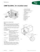
To avoid clogging, fit a water filter, item 4 (with a max. mesh of 500
μm), between the shut-off valve and the humidifier.
1. Control box, on the outside
2. Control box, on the inside
3. Shut-off valve (not included)
4. Water filter, max. 500 mm mesh (not included)
5. LQAZ-08 Water trap (accessory)
6. Water supply pipe
7. Humidifier fill
8. Droplet eliminator
9. Spray pipe
10. Pump
11. Flow controller
12. Valve with motor actuator
13. Overflow hose
14. Water level sensor
15. Solenoid valve
16. Flushing hose
17. End plug
18. Side wall
Nominal pipe size/Diameter
Water supply pipe Drain connection
No. 20, 3/4” BSP 2 No. 32 dia. conn. male thread
LQQA Size /
Degree of
humidification
Number of pumps
Pump: Output, 0,12 kW
Power supply: 3x230 /400 V
Current: 0,71/0,41 A
Pump: Output, 0,18 kW
Power supply: 3x230/400 V
Current: 0,86/0,50 A
60/60-90% – –
62,71,80/60% 1 1
62,71,80/90% – –
64, 73/60–90% 2 –
82, 84/60% 2 –
82, 84/90% – 2
PE
N
T1
HB
T2
T3
L1
L2
L3
PE
1
2
3
4
PE
Power supply 3 x 400 V + N + Pa 50 Hz 10 A
Interlock
from SF
Moisture
control
Fig. 1
17
18
3
2
4
16
15
14
1
9
7
8
10
11
12 13
5
6
Size 60-84
TO CONNECT THE HUMIDIFIER TO THE WATER
SYSTEM
The water supply to a humidifier is controlled by a builtin solenoid
valve. Connect the supply pipe to the inlet branch. Fit a shut-off valve,
item 3.
TABLE 1. CONNECTIONS – NOMINAL PIPE SIZES
WIRING DIAGRAM FOR THE CONTROL BOX ON OUTSIDE
Connect the drain pipe, item 6, to the humidifier drain connection. This
should be fitted with a cleanable water trap, item 5, and should be run,
without reduction in diameter, to a floor gulley. For size 44, 52–84 hu-
midifiers, two water traps should be used in parallel.
The shut-off valve, water trap and water filter are not included in the
supply.
CONNECTION TO THE POWER SUPPLY
(to be carried out by an authorized electrician)
When making the connections on site, run the power supply cable,
item 1, to the control box through the cable gland fitted to the casing.
External fuse: at least 4 A.
The electrical components inside the control box are protected by a
2A fuse.
The pump is delivered always connected for 3 x 400 V. The pump
motor has degree of protection S 33 (IP 44) and has class B insulation.

LQQA Humidifier for circulated water - Installation instruction
2
FläktGroup DC_9150GB 20180418_R0
Specifications are subject to alteration without notice
MAINTENANCE ADJUSTMENTS
WATER:
Determine the calcium and bicarbonate content and the pH value of
the water. These values can be obtained from a water analysis or from
the local water authority.
Plot the values of bicarbonate, calcium and pH in chart 1 on page 5 to
determine in which zone the water can be classified. If the water is of
zone 4 type, it should be softened.
LEVEL MONITORS FIG. 2
Level monitor A: Closes the water supply valve when the water
reaches max. level A.
Setting A: 65 mm from the upper edge of the water tray
(sizes 60–84).
Level monitor B: Opens the drain valve for water bleed-off.
Setting B: The zone value obtained (see page 5) determines at
which setting level monitor B (Fig. 2) is to be preset.
Set the marking on the monitor in relation to the zone
scale.
Level monitor C: Stops the circulation pump and opens the water
supply valve if the water level drops below level C.
Setting C: 25 mm from the bottom of the water tray (sizes 40–84)
Level relays:
NR 1, NR 2 and NR 3 are shown in Fig. 7. The level relays are preset at
a sensibility of 40 kΩ. If softened water is used and the level monitors
don’t work, the sensibility setting can be increased to 100 kΩ.
THE HUMIDIFER FUNCTION:
– switch on the power supply to the humidifier. The water tray will
start to fill with water.
CHECK:
– that the pump has started and that it is pumping water. If there is
no water flow, change the direction of rotationof the pump, see Fig. 5.
– preset the required supply water flow rate according to Table 2.
This is done by setting the adjustment screw on the flow controller,
shown in Fig. 4.
– that water is being discharged from all of the holes in the spray
pipe(s). If any holes are clogged, use a needle to unclog them. If the
spray pipe(s) is/are extremely clogged, remove the end plugs (17),
brush inside them using a round brush and then flush them clean.
– that the flow of supply water stops when the water level in the tray
reaches level monitor A.
– that water bleed-off can be done by manually opening the drain
valve approx. half way (45°), see Fig. 3. The valve can be reclosed by
pressing a reset button on the control unit. When the water level has
dropped below the lowest point of sensor B, the drain valve should
open fully. If the water level continues to drop below the lowest point
of sensor C, water inlet valve should begin to open and after a pre-
set period (see Table 2, Fig. 6) the drain valve should start to close.
When the water reaches level C, the pump should soon stop. (The
pump should not run when the water level is below level C.)
– The preset period on the time relay should be accoring to Table 3, 4
and Fig. 6.
DROPLET ELIMINATOR
Closes the water supply valve when The droplet eliminator fills must
be correctly fitted for the direction of air flow, see the arrow on the
droplet eliminator.
1
2
3
ZON
ABC
Zon
3
2
1
ZON-skala
Nivåvakt B: inställbar
Inställningsskruv
Nivåvakter
Level monitors
Zone Scale
Level monitor B: adjustable
Adjusting screw
EUQA 2;1
Fig. 3
Fig. 4
Fig. 2
00
2
4
246
30
20
10
EUQA Pump
Adjusting screw
Reading point
Fig. 5
Size
Supply water flow, l/min
Aluminium
90% 60%
60
62
64
30
40
50
15
20
25
71
73
40
50
20
25
80
82
84
40
50
60
20
25
30
TABLE 2. SUPPLY AIR FLOW

LQQA Humidifier for circulated water - Installation instruction
3
FläktGroup DC_9150GB 20180418_R0
Specifications are subject to alteration without notice
Time relay TR1 has been preset for normal operation. If the time re-
quired for emptying has to be increased due to humidification over a
long period, this can be done as follows:
1. Select Function 12
2. Select the Range
3. Select Time
– If Range has red digits, Time shows tenths of Range
– If Range has black digits, Time shows thirtieths of Range.
Example: Size 64, Δx >8 gram.
Set a time of 240 sec.
– Select a Range of 300 sec. (black digits)
– Select a Time of 24 (black digits)
TABLE 3. TIME REQUIRED FOR EMPTYING (TIME RELAY TR1)
Size
Time required for emptying
Normal operation
preset value
High humidification
over a long period
Δx >8 gram Δx >5 gram
90% 60% 90% 60%
60
62
64
30
60
60
0
0
30
30
90
240
0
0
120
71
73
60
90
30
60
180
240
90
120
80
82
84
90
90
120
60
60
60
180
240
300
120
120
120
Range
Time
ETR4–69–A
Function
1s
1.5 .5
12
M
A1~+ 15 B1
A2~-1816
Rel Power
TR1
Fig. 6
Seconds
0
Range
1 s
Time
0
10 10 s 10 red
20 30 s 20 black
30 30 s 30 black
40 100 s 4 red
50 100 s 5 red
60 100 s 6 red
70 100 s 7 red
80 100 s 8 red
90 100 s 9 red
100 100 s 10 red
120 300 s 12 black
180 300 s 18 black
240 300 s 24 black
300 300 s 30 black
Q1
K1
R1
NR3
NR2NR1
TR1
Fig. 7 Components inside the control box
WATER BLEED-OFF
The water consumption consists of the water evaporated and a certain
amount of water bleed-off. This bleed-off flow is necessary to reduce
the consumption of salts in the circulating water. If the concentration of
salts is too high, salts may be deposited on the humidifier fill, which
will have a detrimental effect on the performance and useful life of the
humidifier.
TO SET THE TIMER FOR EMPTYING AND FLUSHING
For normal function, the timer should be preset to ”ON”. When emp-
tying, which can be programmed to occur once or several (optional)
times every 24-hour period, the timer will reset itself to the ”OFF” set-
ting for 10 minutes. After that, the timer will reset itself to ”ON” for 2
minutes to allow flushing. The timer will then reset itself to the ”OFF”
setting for 3 minutes for additional emptying before resetting itself
back to ”ON” for normal operation.
In the following example, emptying and flushing are required once
every 24 hours from 12.00 to 12.15 as scheduled below.
Period Timer setting Activity
00.00–12.00 ON Normal operation
12.00–12.10 OFF Emptying
12.10–12.12 ON Flushing
12.12–12.15 OFF Additional emptying
12.15–24.00 ON Normal operation
This can be done most easily by programming the operation times
from 12.15 to 12.00 and from 12.10 to 12.12 on a daily basis!
Emptying and additional emptying will then occur from 12.00-12.10 and
12.12 - 12.15.
Chart 1 can be used to determine the appropriate bleed-off flow, to
suit the water quality zone and the humidification rate. Level sensor B
should be preset to the appropriate zone, correct bleed-off will then be
achieved.
In order to insure that the water tray is kept clean, it is advisable to
drain and flush it every day (preset at the factory at 12.00–12.15 hours).
If high demands on hygiene are made or if the humidifier runs over a
long period at a high humidification rate, Δx above 8 grams per kg of
air (90 % humidifier) and Δx above 5 grams per kg of air (60 % humidi-
fier), it is advisable to program an additional daily draining and flushing
cycle.

LQQA Humidifier for circulated water - Installation instruction
4
FläktGroup DC_9150GB 20180418_R0
Specifications are subject to alteration without notice
TIMER
The timer has been preset at the factory for emptying and flushing as
described above once every 24-hour period.
The timer has also been preset for the following:
– Summer and winter time in the country where it is to be used.
– Date and time in the time zone where it is to be used.
CHANGE OF CURRENT TIME OF DAY
1. Press menu 2 times - flashes
2. Press OK
Display shows YEAR, change with + or –
3. Press OK
Display shows MONTH, change with + or –
4. Press OK and continue for DAY, HOUR, MINUTE, SU/WI…
(SU = Summer, WI = Winter)
For switching ON/OFF
1. Press menu 1 time - Prog flashes
2. Press OK
3. Change to QUESTION with + or –
4. Press OK
5. Press OK for next time.
And continue to END
6. Press OK
CHANGE OF ON/OFF
1. Press menu 1 time - Prog flashes
2. Press OK
Read text in the display!
Select with + or –
Store with OK
MANUAL OPERATION OF ON/OFF
1. Press both + and – at the same time.
~ 1 sec gives manual ON/OFF, (returns automatically)
~ 2 sec gives permanent ON/OFF
RESETTING:
Briefly press both + and – at the same time.
For further particulars, see the separate instructions supplied with the
timer.
To INTERRUPT
Press menu
The numbers under the display indicate days of
the week
1 = Monday, 2 = Tuesday, etc.
N
L1
L2
1 2 3 N
MENU OK
-+
1 2 3 4 5 6 7
0
L
Auto
24
Display of special functions:
Manual operation
Permanent ON/OFF
Symbols which indicate summer/winter function:
Summer
Winter
Choice Yes means choice of programming.
Choice No means continue.
Duct status
ON = On, OFF = OFF
❄
Day-by-day summary of the
programmed connection times.
Example: 5 = Friday
Maintenance voltage OK:
Indicated by 2 flashing points
between the numbers on the
display.
Running reserve mode:
Indicated by 3 flashing points
between the numbers on the
display.
Choice of function:
Ex: Auto, Prog, Pulse,
Cycle, Delete

LQQA Humidifier for circulated water - Installation instruction
5
FläktGroup DC_9150GB 20180418_R0
Specifications are subject to alteration without notice
DETERMINING THE WATER QUALITY ZONE
The following particulars are required to be able to determine the
water quality zone.
■ the pH of the water
■ the bicarbonate concentration (HCO3– ), mg/l
■ the calcium concentration (Ca2+), mg/l
This data can be obtained from a municipal water authority or by
analysing the water.
CHART 1
EXAMPLE
Data from the municipal water authority:
pH = 7,6
Bikarbonate = 0 mg/l
Calcium = 30 mg/l
From Chart 1, the operating point is in zone 1 (safe zone).
Zone 1 is the safe zone, in which the water is soft or demineralized.
Zone 2 is the lower part of the transition zone, in which the water can
be said to be of normal drinking quality.
Zone 3 is the upper part of the transition zone, in which the water is
relatively hard.
Zone 4 is the precipitation zone, in which the water is very hard. The
water must be subjected to partial softening, so that its quality will be
within zone 2–3.
However, the softening treatment must not lower the quality of the
water to zone 1.
10 10 000
6000
2000
4000
1000
600
400
200
100
60
40
20
10
6
4
2
1
567898,5 9,5
42620 40 60 100 1000 10 000
Calcium Ca2+ eulav-Hpl/gm Max. pH of aluminium
Bikarbonate HCO3
–mg/l
Precipitation zone
Transition zone
Safe zone
pH-value Max. pH of aluminium
Bikarbonate HCO3– mg/l
Calcium Ca2+ mg/l
4
2
1
3
/