FläktGroup Woods Industrial Cooling Fan O&M Installation guide
- Type
- Installation guide

INDUSTRIAL COOLING FAN
Safety, installation and
maintenance instructions
Part Number 915960

2
CONTENTS PAGE
STANDARD VENTILATION FANS
1 SAFETY ..................................................................................................................................................................................................... 4
2 INTRODUCTION & PURPOSE - GENERAL ..................................................................................................................................... 4
3 STORAGE & HANDLING ..................................................................................................................................................................... 5
4 MECHANICAL INSTALLATION ......................................................................................................................................................... 5
5 ELECTRICAL INSTALLATION & OPERATION ............................................................................................................................... 6
5.1 - OVERHEAT PROTECTION ........................................................................................................................................................... 7
5.2 - BEARING TEMPERATURE, VIBRATION & LEVEL MONITORING SENSORS ...................................................................... 7
5.3 - ANTI-CONDENSATION HEATER ................................................................................................................................................ 7
5.4 - SWITCH-ON ................................................................................................................................................................................... 7
6 MAINTENANCE ...................................................................................................................................................................................... 8
6.1 - FIXINGS .......................................................................................................................................................................................... 8
6.2 - LUBRICATION ............................................................................................................................................................................... 8
6.3 - INFREQUENT USE ........................................................................................................................................................................ 8
7 OVERHAUL / EXTENDED MAINTENANCE .................................................................................................................................... 8
8 FAULT FINDING .................................................................................................................................................................................... 9
8.1 - ELECTRICAL ................................................................................................................................................................................... 9
8.2 - MECHANICAL ................................................................................................................................................................................ 9
9 DISPOSAL ............................................................................................................................................................................................... 10
10 EUROPEAN MACHINERY DIRECTIVE 2006/42/EC 10 ............................................................................................................... 10
DECLARATION OF CONFORMITY ....................................................................................................................................................... 10
EC DECLARATION OF CONFORMITY ............................................................................................................................................... 11
3
TABLE
1 ROUTINE MAINTENANCE PROCEDURES .......................................................................................................................................... 12
FIGURES
1 WIRING DETAIL - THREE PHASE FANS WITH DUCT MOUNTED TERMINAL BOX ................................................................. 13
2a DRAWINGS OF FAN COMPONENTS WITH FIXING METHODS SHOWN .................................................................................. 14
2b DRAWING OF TORQUE SETTINGS FOR FIXINGS (DRAWING NO: D248284) ..................................................................... 15
THIS LEAFLET MUST BE PASSED TO THE USER
TO ENABLE THE FAN TO BE MAINTAINED IN A SAFE CONDITION.

4
1. SAFETY
Warning and safety information relevant to specic operations are contained within each section. The following warning
or advice categories are used:
DANGER! Failure to follow these instructions may result in serious injury or death to the user in addition
to serious damage to the equipment.
WARNING! Failure to follow these instructions may result in minor injury or damage to the equipment.
CAUTION! Failure to follow these instructions may result in malfunction or damage to the equipment.
NOTE! Additional instructions to consider.
2. INTRODUCTION & PURPOSE - GENERAL
The Industrial Cooling Fans are highly ecient air movement products, designed to operate within a temperature range of
-40° to +60°C (suitable for starting at -40°C). When operating at low temperatures, ice formation on the fan assembly must be
prevented.
Each fan assembly has been manufactured specically to full the requirement of the installation for which it was designed.
No deviation from the original requirement must be implemented without referring to Woods Air Movement head oce
(located in Colchester, UK). Any queries regarding safety or operating problems must be referred to your local Woods Air
Movement oce, sales centre or representative, together with full fan/motor nameplate details. Should a fan failure occur
whilst the product is under warranty, the Woods Air Movement service centre in Colchester must be contacted before any
repair work is undertaken.
Only approved, qualied personnel familiar with the assessment of hazards and risks associated with fans, and with the use
of tools and test equipment required to service such fans, should install, operate, and maintain the product. If the installer or
user is unable to understand the information in this manual or has any doubt that safe and reliable installation, operation, and
maintenance of the equipment can be assured, Woods Air Movement or their representative must be contacted for advice.
If speed control is to be provided by means of a frequency inverter, please seek drive selection and compatibility
advice from Woods Air Movement.
CAUTION! The motor should not be removed from the product or modied in any way.
THIS LEAFLET MUST BE PASSED TO THE USER
TO ENABLE THE FAN TO BE MAINTAINED IN A SAFE CONDITION.
3. INSPECTION, STORAGE & HANDLING
WARNING! When storing fan assemblies, please ensure that access by unauthorised personnel is prevented
by using guards, barriers, or secure premises, so that fan impellers, which may be rotating (wind
milling), do not present a hazard.
Check immediately on receipt that the fan is as ordered and that it has not been damaged in transit.
Where the fan is delivered in a crate (or similar) the crate must be considered as a protective device for transit only.
The crate must not have other equipment stacked on top of it and it must not be stacked on top of other equipment. The crate
structure must not be used as a lifting aid, unless otherwise indicated.
Where a fan is packed inside a crate, a fork-lift truck or similar must be used to transport the product. The fan must be stored
in a safe, clean, dry, vibration free location. If such storage conditions are not available, the motor anti-condensation heater
(where tted) should be connected to an appropriate electrical power supply to prevent motor condensation forming, while the
fan should be stored in an appropriate enclosure. Each month, the fan impeller should be given a manual rapid spin to help
prevent grease from hardening and possible bearing brinelling. If the impeller must not remain in the same angular position
after rotation.
When dismantling the crate to gain access to the fan assembly care must be taken to avoid injury from sharp edges, nails,
staples, splinters, etc. If the fan is to be stored for 12 months or more, then the activities described in Section 6.3 should be
carried out.
It is highly recommended that the fan is inspected by a member of the Woods Air Movement service team before
commissioning is undertaken.
4. MECHANICAL INSTALLATION
DANGER! It is recommended that suitable safety guards form part of the installation. Advice on these, and
similar safety devices, are available from Woods Air Movement.
WARNING! Where the fan is delivered in a crate (or similar), the crate must be considered as a protective
device only and must not be used as a lifting aid unless clearly indicated otherwise.
WARNING! All lifting aids used during installation must be appropriately certied to carry the weight of the
equipment being lifted.
WARNING! The correct protective clothing (including hard hats, eye protectors and ear defenders) should
always be worn when working with and in the vicinity of the fan assembly.
WARNING! During lifting of the fan all personnel must be clear of the area below and around the suspended
fan.
NOTE! Before fan assembly installation, check that no damage has occurred in transit, that there is no fan
casing deformation, that the impeller rotates freely and that the fan and motor nameplate data
complies with its required use. If the fan assembly has been stored for longer than a month please
refer to Section 6.3.
Fan assemblies can sometimes be very heavy (depending on fan and motor size and any attached ancillary equipment),
which can make them unwieldy during handling. They must therefore be lifted slowly to prevent damage or distortion. Proper
precautions must be taken, and certied lifting aids used, to ensure that the fan is well supported and stable before lifting
into position. Care must be taken when installing fans to ensure that the product orientation is correct in relation to direction
arrows which indicate direction of air movement and impeller rotation direction.
5

Flange holes or mounting feet holes can be used for lifting but more than one hole must be used to spread the load.
If special lifting points are provided, they must be used. The fan must be installed such that it is correctly positioned in
accordance with the required airow direction. An airow indication arrow is shown on the fan nameplate.
Sharp bends in the ductwork close to the fan must be avoided. Adequate room must be allowed around the fan for inspection
and maintenance. When ancillary component parts are included in the fan assembly, such as anti-vibration mounts, silencers,
bellmouths, air operated dampers, exible connectors (and their clips), weather proong, platforms, supports, chains, and
harnesses, etc. they must be fully aligned before being bolted together so that no distortion or stress is placed on the
equipment. Air operated dampers must be installed downstream of the fan (on the fan discharge) to ensure that fan
performance is not adversely impacted.
The fan mounting and support structure must be strong and rigid enough to take the weight and operating forces of the
fan and any other weight applied during installation. Consideration must be given to mitigation of vibration transmission. If
vibration isolators are used they must be appropriate for the weight and thrust of the fan and must not be used to compensate
for misaligned component xing points. If any component parts do not easily t together the root cause must be investigated
and rectied.
Provision for drainage is provided in each motor end cover and electrical connection terminal box. The motor drain hole must
be located at the lowest point of the motor when the fan is installed. Periodic inspections should be carried out to ensure there
is not a general build up of condensation. The frequency will depend on the environmental conditions and should be recorded
within maintenance records. To maintain the IP rating, the plugs must not be permanently removed.
After installation all packing materials must be disposed of in accordance with the instructions advised in Section 9.
5. ELECTRICAL INSTALLATION & OPERATION
DANGER! Before any work can be attempted, the fan assembly, its anti-condensation heater (if tted) and all
controls must be completely isolated from electrical supplies. Ensure that rotating parts are fully at
rest.
WARNING! Before entering the area where the fan is installed, please ensure that all fumes, dust, toxic
emissions, heat etc. have dispersed from the local environment, and that the fan blades are not
likely to rotate.
DANGER! The fan assembly contains rotating parts and electrical connections which can be a danger and
cause injury. If there is any doubt that a safe and reliable fan installation can be achieved Woods Air
Movement or their representative must be contacted for advice.
DANGER! If the fan stops operating due to an overheat situation, the overheat protection thermostat may
reset as the temperature cools and then automatically restart the fan if power is still applied.
WARNING! Always wear appropriate protective clothing (including hard hats, eye protectors and ear defenders
etc.) when working in the vicinity of the fan assembly.
The electrical supply and electrical earthing must be connected to the terminal box by a qualied and competent electrician.
It is good practice to t a clearly marked isolator switch close to the product, preferably of the lockable type which will allow
the operator or maintenance engineer to isolate the product from the electrical supply before working on the assembly.
Alternatively, we recommend the use of a second clearly marked and accessible switch remote from the product to provide an
enhanced level of safety when isolating the product during maintenance.
Sucient cable length must be provided to allow for movement of the fan on its mountings.
A connection diagram providing wiring details is supplied with all fan assemblies (typically inside the terminal box lid).
See Figure 1 on page 13 for wiring terminal details.
Electrical control circuit fuses must be correctly selected to carry the rated starting current as indicated on the motor or
fan nameplate but should only be regarded as oering protection against wiring short circuits or earth faults. Fuses are not
designed to provide overload protection. To provide full protection for the motor, a starter panel with overload protection must
be used.
6
If the fan is to be powered by a variable frequency drive (inverter) then appropriately shielded cable and adequate earthing
must be used. The use of eective voltage waveform lters is recommended.
Fans with a duct-mounted terminal box must have their electrical supply cables routed through an entry point in the side of
the box. Unused entry points must be sealed with weatherproof plugs or grommets. Fans with a motor-mounted terminal box
must also have its electrical supply routed through an entry point in the side of the terminal box.
Cables must be routed via a gland assembly. The gland assembly should be tightened suciently to hold the cable and provide
a weatherproof seal, but it must not be over-tightened.
5.1 OVERHEAT PROTECTION
Thermostats are wired to separate terminals (K – K) within the terminal box; they operate by opening and closing with
temperature and must be wired to directly disengage the motor start contactor. Other overheat protection options may
have been requested - please refer to your local Woods representative.
NOTE! When a motor cools down, an over-heat protection device will reset. However the motor must not
be allowed to start until the motor start contactor is manually reset.
5.2 BEARING TEMPERATURE AND VIBRATION MONITORING SENSORS
If monitoring sensors are tted into the fan control system, then they must be wired to automatically switch the fan o if a fault
occurs, or to provide a fault indication. If the fan is automatically switched o by a monitoring sensor the control system (via
a PLC for example) must ensure that the fan is fully isolated from the electrical supply, so that it will not automatically reset
and re-start.
5.3 ANTI-CONDENSATION HEATER
Anti-condensation heaters are terminated in a terminal box on the fan and must be externally wired to automatically receive
the appropriate electrical supply when the motor is switched o. When the motor is switched on the anti-condensation heater
is not required and thus must be automatically switched out of circuit.
5.4 SWITCH ON
Before switching on,Before switching on,
• conrm that the electrical supply is fully compliant with the requirement of the motor as detailed on the motor or fan • conrm that the electrical supply is fully compliant with the requirement of the motor as detailed on the motor or fan
nameplate,nameplate,
• conrm that the fan is correctly installed,• conrm that the fan is correctly installed,
• check all component parts and xings are secure,• check all component parts and xings are secure,
• conrm that safety guards are in place,• conrm that safety guards are in place,
• check that no loose items or associated equipment are present in the vicinity,• check that no loose items or associated equipment are present in the vicinity,
Immediately after switch-on check that the direction of impeller rotation and air movement is correct,
• for three phase motors, if the rotation direction is incorrect, then this can be rectied by interchanging any two incoming
phase connections of the electrical supply at the motor terminal block,
• check the assembly for smooth, low vibration running,
• check that the current consumption is within the full load current specied on the nameplate,
• the fan motor must not be repeatedly or rapidly switched on and o as this could cause overheating of the motor or its
associated wiring connections.
5.5 OPERATION
Fans must not be operated above their maximum indicated speed or run where the fan is operating in a stalled or unstable
condition.
Fans must not be run in reverse unless specic advice is sought from Woods Air Movement.
7

6. MAINTENANCE
DANGER! Before any maintenance work can be attempted, the fan assembly, its anti-condensation heater (if
tted), and all controls from electrical supplies must be completely isolated. Ensure that rotating
parts are fully at rest and that fan blades are temporarily restrained to prevent rotation of the
impeller.
WARNING! Before entering the area where the fan is installed, please ensure that all fumes, dust, toxic
emissions, heat etc. have dispersed from the local environment.
WARNING! All lifting aids used during maintenance, and all lifting points utilized, must be adequately certied
to carry the weight of the equipment being lifted.
WARNING! Always wear appropriate protective clothing (including hard hats, eye protectors and ear defenders
etc.) when working in the vicinity of the fan assembly.
Fan assembly maintenance must be carried out by appropriately qualied and competent personnel using the correct
tools and equipment. A regular maintenance schedule should be established, and a record kept. It is recommended that
the maintenance activities given in Table 1 (page 12) are followed. Maintenance records are required to be documented
throughout the warranty period.
Where the environment is particularly dirty, it may be necessary to reduce maintenance / service intervals. Internal and external
fan surfaces may be cleaned with low pressure clean water and non-abrasive additives. Water or liquid cleaning agents must
not be directed at motor drain holes, as this could cause liquid ingress.
After maintenance has been conducted and before the fan is re-started, always ensure that there are no loose items of
equipment present in the vicinity of the fan, that all safety guards, chains, or steel ropes, etc., are properly secured into their
original location, and that any temporary device used to stop the fan impeller from rotating has been removed.
6.1 FIXINGS
It is essential to ensure that all fan assembly xings are secure. When examining and checking the security of xings during
routine maintenance (see Table 1 Items 11 and 12), any xings which have locking devices tted or are painted over, need
not be disturbed if it can be seen that they are secure. Any locking devices that are disturbed during maintenance must be
discarded and replaced with new identical devices. Thread forming screws must have locking compound applied when being
reused. Any xings which have no locking devices tted and are not painted over, must be checked at 95% of their original
torque setting to ensure that no unnecessary disturbance of the xing has occurred. See Figure 2b (Page 15) for torque setting
details. If in doubt, please contact Woods Air Movement for advice in relation to specic xing torque values.
6.2 LUBRICATION
In addition to routine maintenance, motor bearings will, in the longer term, require attention. If motor bearings are greased
through extended lubricators, then the required quantity of grease must periodically be applied in accordance with information
stated on the fan or motor nameplate and/or as per any instructions provided. Only the approved grease type should be used,
and it is essential that all traces of water and dirt are removed from around the grease points and that a clean grease gun is
used. It is only necessary to apply a small amount of pressure to inject the specied quantity of grease. If a high pressure is
required then the cause should be investigated.
Where motors require re-lubrication, a separate instruction is normally issued with each fan/motor conguration.
This gives details of lubrication intervals and well as the type and quantity of grease to be used. If further details are required,
please contact Woods Air Movement directly.
8 9
6.3 INFREQUENT USE
If the fan assembly is used less frequently than once a month, the following additional maintenance procedures must be
carried out and a record kept:
- Resistance of motor windings to earth, must be measured with a 500 V DC insulation tester each month. If these readings are
less than 10 MΩ (Megaohm), the motor must be dried out in a warm airow (typically at 40°C) and re-checked before running
the motor.
- The fan should be operated between 15 and 30 minutes each month to ensure that correct lubricant conditions are
maintained within the bearings (i.e., to prevent grease hardening).
- If anti-condensation heaters are tted, check each month that they automatically switch on (i.e., they are drawing current)
when the motor is switched o.
7. OVERHAUL / EXTENDED MAINTENANCE
Advice on motor overhaul procedures, bearing /seal replacement, motor replacement, motor rewinding, spare parts, condition
monitoring, vibration analysis, refurbishment, etc. is available from Woods Air Movement service centre in Colchester.
After 40,000 hours of running, we strongly recommend that a qualied and competent electrician performs a motor “health
check” (as described within Section 8, Fault nding) to determine the motor insulation condition.
NOTE! The motor manufacturer’s specication sheets are available through Woods Air Movement. After
overhaul/extended maintenance the fan assembly must be correctly installed back into its original
position.
8. FAULT FINDING
Please refer to the safety warnings (“attention” items) stated within Section 1 and 6.
NOTE! Routine maintenance procedures detailed in Section 6, and Table 1 of this document are designed
to help keep your fan operational and fault free.
8.1 ELECTRICAL
Check that electrical connections to the fan are secure and are in accordance with the wiring connection diagram.
Check that the voltage applied at each fan terminal is as specied on the fan nameplate and is balanced. Measure the current
on each phase of the motor in turn and check that the current consumption is within the full load current specied on the
motor or fan nameplate.
Measure each motor winding to earth, and between each winding, using a 500 V DC insulation tester. If the reading is less than
10 MΩ the reason is likely to be dampness within the motor. To dry out the motor place it in a warm dry airstream (typically at
40°C) and regularly monitor the motor until the insulation reading is restored to 10 MΩ or greater. If the reading remains at
less than 10 MΩ, then this could indicate that a break-down in motor winding insulation has occurred, which may require the
motor to be either rewound/overhauled.
If a smell of burnt motor insulation is detected, then please seek immediate advice from Woods Air Movement Colchester.
8.2 MECHANICAL
Check that there are no obstructions to the motor shaft or impeller blades, that the blades are clean, and that there are no
loose components, items, or debris in the vicinity.
Rotate the motor shaft by hand. Investigate any grinding noises, internal chang, rubbing or stiness. If any of these defects are
observed, this may indicate that bearings require lubrication or replacement.
Ensure that all xings are secure and tightened to the correct torque values.

10
9. DISPOSAL
NOTE!
Metal components of the fan/motor should be segregated and separately recycled. The following items of material
should be safely disposed of in accordance with local health and safety regulations:
- electrical lead coverings,
- motor winding insulation materials,
- bearing lubricant,
- motor/fan terminal block,
- paintwork,
- plastic parts,
- packing materials,
- silencer inll
WARNING! A face mask and gloves must be worn when handling the inll. If the inll is particularly dry
or is damaged it should be damped down before disposal.
10. DECLARATIONS OF CONFORMITY
11
Herewith we declare that the air movement equipment designated below, on the basis of its design and construction, in the
form brought on to the market by us, is in accordance with the relevant health and safety requirements of the
EC Council
directives on Machinery and Electromagnetic Compatibility
and also ecodesign requirements for energy-related products.
If alterations are made to the machinery without prior consultations with us, this declaration becomes invalid. We further
declare that the equipment identified below may be intended to be assembled with other equipment/machines to
constitute machinery, which shall not be put into service until the assembled machinery has been declared in conformity
with the provisions of these EC Council directives.
Notes:
(1)
Fläkt Woods fans are driven by AC induction motors which are inherently compliant if supplied with a truly sinusoidal AC supply.
Where the fan motor is supplied via an inverter or other electronic control, verification of its compatibility together with cabling should be
sought from the control supplier.
(2)
For a complete list of applied standards and technical specifications see Fläkt Woods documentation.
(3)
Where no relevant harmonised standards exist.
Designation of equipment:
Series / type:
Fläkt Woods Limited order no:
Relevant EC Council directives:
Applied harmonized standards
in particular (2):
Applied national standards
and technical specifications
in particular (3):
Basis of self attestation:
Technical file compiled by:
Industrial Cooling Fans
Machinery Directive (2006/42/EC).
Electromagnetic Compatibility Directive (2014/30/EU) where applicable (1)
Energy-related products Directive (2009/125/EC) relevant implementing measures:
REGULATION (EU) No 327/2011, REGULATION (EU) No 1253/2014, where appropriate
EN ISO 12100:2010, EN 60204-1:2018, EN ISO 12499:2008, EN ISO 5136:2010
EN ISO 5801:2017, EN ISO 13350:2015, EN IEC 61000-6-2:2019, EN 61000-6-1:2007
EN 61000-6-3:2007/A1:2011/AC:2012, EN 61000-6-4:2007/A1:2011
BS 848.2-1:2004 (BS ISO 13347-1:2004/A1:2010)
BS 848.6:2003 (BS ISO 14695:2003)
BS 848.7:2003 (ISO 14694:2003/A1:2011)
Quality Assurance to BS EN ISO 9001:2015
BSI Reg Firm Cert No. FM 155.
Ömer Tüzer
FläktGroup Holding GmbH, Bahnhofstr. 65-71, 44623 Herne, Germany
Signed for and on behalf of the
manufacturer by:
Place: Colchester
Date: 03/10/2023
Position of signatory:
Stéphane Maravel
Chief Officer Woods
Fläkt Woods Limited t/a Woods Air Movement
Axial Way
Colchester CO4 5ZD
United Kingdom
Tel: +44 (0) 1206 222555
Email: [email protected]
Website: www.woodsairmovement.com
Registered in England no. 233771
Registered office: Axial Way, Colchester, CO4 5ZD, United Kingdom
© Fläkt Woods Limited October 2023
EC Declaration of Conformity
Herewith we declare that the air movement equipment designated below, on the basis of its design and construction, in the
form brought on to the market by us, is in accordance with the relevant health and safety requirements of the
UK
Parliament Regulations on Product Safety, Electromagnetic Compatibility and Ecodesign for Energy-Related Products.
If
alterations are made to the machinery without prior consultations with us, this declaration becomes invalid. We further
declare that the equipment identified below may be intended to be assembled with other equipment/machines to
constitute machinery, which shall not be put into service until the assembled machinery has been declared in conformity
with the provisions of these UK Parliament Regulations.
Notes:
(1)
Fläkt Woods fans are driven by AC induction motors which are inherently compliant if supplied with a truly sinusoidal AC supply.
Where the fan motor is supplied via an inverter or other electronic control, verification of its compatibility together with cabling should be
sought from the control supplier.
(2)
For a complete list of applied standards and technical specifications see Fläkt Woods documentation.
Designation of equipment:
Series / type:
Fläkt Woods Limited order no:
Relevant UK Regulations:
Designated standards
in particular (2):
Basis of self attestation:
Technical file compiled by:
Industrial Cooling Fans
Supply of Machinery (Safety) Regulations 2008
Electromagnetic Compatibility Regulations 2016 where applicable (1)
Ecodesign of energy-consuming products relevant implementing measures:
REGULATION (EU) No 327/2011, REGULATION (EU) No 1253/2014, where appropriate
EN ISO 12100:2010, EN 60204-1:2018, EN ISO 12499:2008, EN ISO 5136:2010
EN ISO 5801:2017, EN ISO 13350:2015, EN IEC 61000-6-2:2019, EN 61000-6-1:2007
EN 61000-6-3:2007/A1:2011/AC:2012, EN 61000-6-4:2007/A1:2011
BS ISO 13347-1:2004/A1:2010, BS ISO 14694:2003/A1:2011,
BS ISO 14695:2003
Quality Assurance to BS EN ISO 9001:2015
BSI Reg Firm Cert No. FM 155.
Iain Kinghorn
Fläkt Woods Limited, Axial Way, Colchester, CO4 5ZD, United Kingdom
Signed for and on behalf of the
manufacturer by:
Place: Colchester
Date: 06/10/2023
Position of signatory:
Stéphane Maravel
Chief Officer Woods
Fläkt Woods Limited t/a Woods Air Movement
Axial Way
Colchester CO4 5ZD
United Kingdom
Tel: +44 (0) 1206 222555
Email: [email protected]
Website: www.woodsairmovement.com
Registered in England no. 233771
Registered office: Axial Way, Colchester, CO4 5ZD, United Kingdom
© Fläkt Woods Limited October 2023
UKCA Declaration of Conformity

12 13
Routine Maintenance Schedule Every 6
Months
Every 12
Months Comments
1. Examine fan guards (if tted) Remove any debris that may have accumulated round or on
the guard surface.
2. Examine motor cooling ns Remove any material or dirt which has build-up between the
motor cooling ns.
3. Examine impeller for dirt build-up or
any physical damage
Remove any build-up of dirt. Ensure impeller is secure.
Replace impeller if it is damaged.
4. Check condition and tautness of fan safety
support chains / harnesses / ropes (if tted)
Clean and inspect safety supports. Replace if there is any
deterioration / corrosion detected.
5. Examine and operate vibration sensors
(if tted), and temperature sensors
(if tted)
Check operation using built-in sensor test features or dummy
signals. Check that the fan is automatically switched o, or that
a warning indication is provided, when the sensors / switches
indicates a fault.
6. Examine condition of safety guards (if
tted) and associated xings
Clean safety guards. Replace if there are any signs of excessive
corrosion or damage
7. Check for condensation build up in the
motor
Remove the drain plugs and check for levels of condensate (see
Section 4)
8. Check operation of anti-condensation
heaters (if tted)
Switch o power to the motor. Check that the anti-
condensation heater is energised (i.e. it is drawing current).
9. Examine the clearance between the
fan impeller blade tips and fan duct.
Check the angle, and the security of
the impeller blades
3
Ensure that the gap between the impeller blade ends and
the fan duct is even and adequate. If in doubt, please contact
Woods Air Movement for advice related to blade tip gap.
Ensure that the impeller blades are secure. Blade angle must
not be changed before contacting Woods Air Movement for
advice.
10. Check torque of xings used to secure
the fan to its support structure.
It is essential to conrm that all xings are properly tted, are
tight, and are fully driven home (see Figure 2a and 2b). If in
doubt, please contact Woods Air Movement for advice related
to the torque value of a particular xing.
11. Examine motor, fan and ancillary
equipment xings
It is essential to conrm that all xings are properly tted,
are tight, and are fully driven home (see Figure 2a and 2b)
If in doubt about the torque of a xing contact Woods Air
Movement for advice.
12. Check movement (deection) of
vibration isolators (if tted)
Check freedom of movement. Tighten anti-vibration mount
xings if necessary.
13. Check motor voltage and current
consumption
Ensure voltage and full load current are as specied on the
motor nameplate
14. Inspect paintwork / galvanising nish Treat any areas of damage with suitable anti-corrosion paint.
15. Lubricate motor bearings Check requirement in accordance with Section 6.2
16. Check fan assembly wiring Check security and condition of all wiring
(including the earth).
17. Check fan operation for excessive
vibration levels
Vibration levels, whilst the fan is operating, should not be
excessive. If levels are seen to have increased since the
previous inspection, the fan must not be operated until the
root cause
has been identied and rectied.
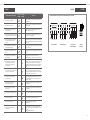
TABLE 1 FIGURE 13-PHASE
WIRING DIAGRAM: THREE PHASE FANS USING TERMINAL BOX ON MOTOR
Star Connection Delta Connection Connection to
Star/Delta Starter
W2 U2 V2
U1 V1 W1
L1 L2 L3
W2 U2 V2
U1 V1 W1
L1 L2 L3
W2 U2 V2
U1 V1 W1
MAX TENSIONE
MAX VOLTAGE
W2
U1 V1 W1
U2 V2
V1
U1 W1
V2U2
W2
MIN TENSIONE
MIN VOLTAGE
0386-02
PROTEZIONE TERMICA
THERMAL PROTECTION
K K
Thermal
Protection

14
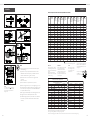
FIGURE 2b
15
FIGURE 2a
NOTE!
1) These gures shown apply unless shown otherwise on specic
assembly drawings.
2) All joints are to be dry except Stainless Steel which is to have
MOLYCOTE 1000 Paste Compound, prior treatment of Loctite
Activator T will decrease curing time if necessary.
3) All values are in Nm. The conversion factor is given for lbf-ft
equipment.
lbf-ft = Nm x 0.7375
4) There is a tolerance on Torque Wrenches up to ± 5%.
5) Nuts are to be tightened only once so no overtightening can occur.
6) The head of the Screw makes no dierence to torque gures other
than how the torque is supplied. The Screw or Base Material are
the important factors for torque.
7) When using two materials always use the lowest gure of the two.
8) The gure to be used on AEG Capacitor Studs is 4 Nm.
9) The material being clamped is only to be taken into consideration
if it is Hollow, very Ductile or Plastic. Please seek advice where
necessary.
TABLE OF TORQUE SETTINGS FOR FIXINGS (DRAWING NO: D248284)
PAD AND FOOT MOUNT TORQUE SETTINGS
ON HOLLOW FOOT USE LOAD SPREADING WASHERS
AND SAME TORQUE AS SOLID FOOT
MOTOR PAD TO ARM FOOT MOUNT
FRAME SIZE THREAD/HOLE ALUMINIUM CAST IRON ALL WASHER
TORQUE SETTING IN Nm
D63/71 M8 TAPSITE 20-25 20-25 20-25
M8 TAPSITE REASSEMBLY 15 15
D63/71 M8 15 15
M10 35 35 50
D80 M12 55 55 85 83770
D90 M12 55 55 85 1504
D100 M12 55 55 85 411590
D112 M12 55 55 85 411590
D132 M16 135 135 180 251691
D160/180 M20 240 240 350 251692
D200 - 315 M24 450 450 267652
LARGER M24 450 450
TABLE 10 SHAFT END FIXINGS
MOTOR SIZE THREAD SIZE TORQUE VALUE
BT4, 5 & 9
CT5, CT9 & D80 M6 006.000
D90S & D90L M8 015.000
F22, D100L & D112M M10 030.000
D132S, D132M M12 050.000
D160M, D160L
D180M, D180L M16 120.000
D200L, D225S
D255M, D250S,
D250M, D280S M20 180.000
D280M, D315S
D315M
D315 ABB M24 295.000
LARGER M24 295.000
BINX NUTS
Binx Nuts Grade 6 are unmarked
and should be tightened to torque
value specied for Mild Steel xings
(all sizes).
Binx Nuts Grade 8 should be
tightened to torque value specied
for Grade 8.8 xings.
RUBBER A/V
Where a rubber grommet or exible
mount is used a metal spacer
tube or metal insert should be
supplied. The rubber should never
be crushed by the xings for any
special application seek advice from
technical support.
NOTE!
Brass xings have half the
shear strength of cast iron
so use half the gures for
tapped cast iron.
TYPE 9
Special arrangement of locking impeller
blade into hub. For this application see
specic assembly DRG only for correct
torque gures.
NOTE
All foot mounted motor xings should be applied with Loctite compound.
For any xings exceeding M24 please contact Engineering for details.
At least x1.5D thread engagement available for cast iron motors and x2D for aluminium motors. If insuciant contact Engineering.
The torque wrenches
should be set to
QCP/002 that is ±5%
NOTE!
The numbers show thus * in the boxes
are to show the screw types and tapped
materials which are appliciable to the
diagram shown.
8 NOTE that Taptite screws may need a high
torque to start the thread forming process
FIXING
SIZE
1
STEEL 8.8
2
STAINLESS
STEEL
A2,A4 PROP 70
3
M.S. FIXINGS
NOT 8.8 GRADE
INCLUDES
T BOLTS
4
STEEL INTO
TAPPED M.S.
5
STEEL INTO
EXTRUDED
AL
6
NUTSERT
7
SCREW INTO
CAST ALUM
ALSO SEE MOTOR
TABLE BELOW
8
TAPTITE
SELF
FORMING
9
INTO CAST
IRON
ALSO SEE MOTOR
TABLE BELOW
2
STAINLESS
STEEL
A2,A4 PROP 80
10
PRESTICERT
M1.6 0.2000 ----- 0.1000 0.1000 ----- ----- ----- ----- 0.050 ----- -----
M2 0.4000 ----- 0.2000 0.2000 ----- ----- ----- 0.400 0.100 ----- 5
M3 1.5000 0.9000 0.8000 0.8000 ----- 1.50 ----- 1.400 0.400 1.2 6
M4 3.5000 2.0000 2.0000 2.0000 ----- 3.50 ----- 3.000 1.000 2.7 9
M5 7.0000 3.9 3.5000 3.5000 ----- 7.00 ----- 6.000 1.750 5.3 11.5
M6 12.000 6.9 6.0000 6.0000 5.00 12.00 7.00 10.000 3.000 9.2 12
M8 28.000 17.0 15.000 15.000 10.00 28.00 14.00 25.000 7.500 22.0 21
M10 55.000 33.0 30.000 30.000 20.00 40.00 28.00 55.000 15.000 43.0 23
M12 100.00 56.0 50.000 50.000 36.00 55.00 50.00 95.000 25.000 75.0 35
M14 155.00 89.0 80.000 80.000 60.00 ----- 85.00 ----- 40.000 119.0 -----
M16 245.00 136.0 120.00 120.00 95.00 ----- 135.00 ----- 60.000 181.0 -----
M18 335.00 191.00 170.00 170.00 ----- ----- ----- ----- 85.000 254.0 -----
M20 475.00 267.00 240.00 240.00 178.00 ----- 200.00 ----- 120.000 356.0 -----
M22 645.00 364.00 325.00 325.00 245.00 ----- 300.00 ----- ----- 485.0 -----
M24 820.00 460.00 410.00 410.00 310.0 ----- 420.00 ----- 450.000 613.0 -----
M27 1200.0 671.00 600.00 600.00 ----- ----- ----- ----- ----- 895.0 -----
M30 1640.0 915.00 820.00 820.00 ----- ----- ----- ----- ----- 1220.0 -----
M33 2225.0 ----- 1115.0 1115.0 ----- ----- ----- ----- ----- ----- -----
M36 2855.0 1600.00 1425.0 1425.0 ----- ----- ----- ----- ----- 2121.0 -----
M39 3700.0 ----- 1850.0 1850.0 ----- ----- ----- ----- ----- ----- -----
M42 4565.0 ----- 2285.0 2285.0 ----- ----- ----- ----- ----- -----
M45 5690.0 ----- 2840.0 2840.0 ----- ----- ----- ----- ----- ----- -----

Woods Air Movement delivers smart and energy
efficient Air Movement and Fire Safety solutions to
support every application area. We offer our customers
innovative technologies, high quality and outstanding
performance.
The widest range of Air Movement and Ventilation
products in the market, and strong market presence
with over 100 years of experience and manufacturing
of products, guarantees that we are always by your
side, ready to deliver Excellence in Solutions.
Contact our friendly sales team today
for more information
Call: +44 (0) 1206 222 555
Email: [email protected]
www.woodsairmovement.com
WAM_DC_00069GB_Industrial Cooling Fan_OM_20230919_R0_.pdf
-
 1
1
-
 2
2
-
 3
3
-
 4
4
-
 5
5
-
 6
6
-
 7
7
-
 8
8
-
 9
9


FläktGroup Woods Industrial Cooling Fan O&M Installation guide
- Type
- Installation guide
Ask a question and I''ll find the answer in the document
Finding information in a document is now easier with AI
Related papers
-
FläktGroup Induction Thrust Fan O&M Installation guide
-
-
-
-
-
-
-
-
-
Other documents
-
ABB MT series Installation And Maintenance Instruction
-
Woods SB64S User manual
-
-
Woods Equipment SB74S User manual
-
 flakt woods LQQA Maintenance Manual
-
Trane CLCH Installation Operation & Maintenance
-
Woods Equipment SS84-2 User manual
-
-
Laguna Tools 14|12 Owner's manual
-
Laguna Tools MBAND1412-175 User manual
