Page is loading ...

Installation, Use & Care Manual
This manual is updated as new information and models are released.
Visit our website for the latest manual. www.manitowocfsg.com
Leader in Ice & Beverage Dispensers
CF-1522
Beverage Dispensers
Part Number 020002472 04/09

We reserve the right to make product improvements at any time.
Specifications and design are subject to change without notice.
Safety Notices
As you work on Manitowoc equipment, be sure to pay
close attention to the safety notices in this manual.
Disregarding the notices may lead to serious injury and/
or damage to the equipment.
Throughout this manual, you will see the following types
of safety notices:
Procedural Notices
As you work on Manitowoc equipment, be sure to read
the procedural notices in this manual. These notices
supply helpful information which may assist you as you
work.
Throughout this manual, you will see the following types
of procedural notices:
NOTE: Text set off as a Note provides you with simple,
but useful, extra information about the procedure you
are performing.
Read These Before Proceeding:
NOTE: SAVE THESE INSTRUCTIONS.
! Warning
Text in a Warning box alerts you to a potential
personal injury situation. Be sure to read the
Warning statement before proceeding, and work
carefully.
!
Caution
Text in a Caution box alerts you to a situation in
which you could damage the equipment. Be sure to
read the Caution statement before proceeding, and
work carefully.
Important
Text in an Important box provides you with
information that may help you perform a procedure
more efficiently. Disregarding this information will
not cause damage or injury, but it may slow you
down as you work.
!
Caution
Proper installation, care and maintenance are
essential for maximum performance and trouble-
free operation of your Manitowoc equipment. Read
and understand this manual. It contains valuable
care and maintenance information. If you encounter
problems not covered by this manual, do not
proceed, contact Manitowoc Foodservice Group.
We will be happy to provide assistance.
Important
Routine adjustments and maintenance procedures
outlined in this manual are not covered by the
warranty.
! Warning
PERSONAL INJURY POTENTIAL
Do not operate equipment that has been misused,
abused, neglected, damaged, or altered/modified
from that of original manufactured specifications.

Table of Contents (continued)
Part Number 020002472 04/09
i
Section 1
General Information
Read This Manual. . . . . . . . . . . . . . . . . . . . . . . . . . . . . . . . . . . . . . . . . . . . . . . . . 1-1
Unit Inspection . . . . . . . . . . . . . . . . . . . . . . . . . . . . . . . . . . . . . . . . . . . . . . . . . . . 1-1
Model Numbers. . . . . . . . . . . . . . . . . . . . . . . . . . . . . . . . . . . . . . . . . . . . . . . . . . . 1-1
Serial Number Location . . . . . . . . . . . . . . . . . . . . . . . . . . . . . . . . . . . . . . . . . . . . 1-2
Warranty Information . . . . . . . . . . . . . . . . . . . . . . . . . . . . . . . . . . . . . . . . . . . . . . 1-2
Section 2
Installation Instructions
General System Overview . . . . . . . . . . . . . . . . . . . . . . . . . . . . . . . . . . . . . . . . . . 2-1
Pre-installation Checklist. . . . . . . . . . . . . . . . . . . . . . . . . . . . . . . . . . . . . . . . . . . 2-2
Unit Dimensions . . . . . . . . . . . . . . . . . . . . . . . . . . . . . . . . . . . . . . . . . . . . . . . . . . 2-4
Location. . . . . . . . . . . . . . . . . . . . . . . . . . . . . . . . . . . . . . . . . . . . . . . . . . . . . . . . . 2-4
Footprints . . . . . . . . . . . . . . . . . . . . . . . . . . . . . . . . . . . . . . . . . . . . . . . . . . . . . . . 2-5
CF-1522 . . . . . . . . . . . . . . . . . . . . . . . . . . . . . . . . . . . . . . . . . . . . . . . . . . . 2-5
Electrical . . . . . . . . . . . . . . . . . . . . . . . . . . . . . . . . . . . . . . . . . . . . . . . . . . . . . . . . 2-6
General . . . . . . . . . . . . . . . . . . . . . . . . . . . . . . . . . . . . . . . . . . . . . . . . . . . . 2-6
Minimum Circuit Ampacity . . . . . . . . . . . . . . . . . . . . . . . . . . . . . . . . . . . . . 2-6
Electrical Requirements . . . . . . . . . . . . . . . . . . . . . . . . . . . . . . . . . . . . . . . 2-6
Voltage . . . . . . . . . . . . . . . . . . . . . . . . . . . . . . . . . . . . . . . . . . . . . . . . . . . . 2-6
Minimum Circuit Amperage Chart . . . . . . . . . . . . . . . . . . . . . . . . . . . . . . . . 2-6
Grounding Instructions . . . . . . . . . . . . . . . . . . . . . . . . . . . . . . . . . . . . . . . . . . . . 2-6
Unit Installation. . . . . . . . . . . . . . . . . . . . . . . . . . . . . . . . . . . . . . . . . . . . . . . . . . . 2-8
Placing the Unit and Operation Setup . . . . . . . . . . . . . . . . . . . . . . . . . . . . . 2-9
Purging Air from the Carbonator Tank . . . . . . . . . . . . . . . . . . . . . . . . . . . . 2-10
Cold Carb and Ambient System Pressures . . . . . . . . . . . . . . . . . . . . . . . . 2-11
Pre-Mix system Installation . . . . . . . . . . . . . . . . . . . . . . . . . . . . . . . . . . . . . 2-11
Plumbing Diagrams . . . . . . . . . . . . . . . . . . . . . . . . . . . . . . . . . . . . . . . . . . . 2-11
Pre-mix Pressures . . . . . . . . . . . . . . . . . . . . . . . . . . . . . . . . . . . . . . . . . . . 2-12
Conversion for non-carbonated flavor . . . . . . . . . . . . . . . . . . . . . . . . . . . . . 2-12
Starting Your Beverage System & Dispenser . . . . . . . . . . . . . . . . . . . . . . . 2-13
Install Labels . . . . . . . . . . . . . . . . . . . . . . . . . . . . . . . . . . . . . . . . . . . . . . . . 2-13
Clean Up . . . . . . . . . . . . . . . . . . . . . . . . . . . . . . . . . . . . . . . . . . . . . . . . . . . 2-13

Table of Contents (continued)
ii Part Number 020002472 04/09
Section 3
Operation
Component Identification. . . . . . . . . . . . . . . . . . . . . . . . . . . . . . . . . . . . . . . . . . . 3-1
Sequence of Operation. . . . . . . . . . . . . . . . . . . . . . . . . . . . . . . . . . . . . . . . . . . . . 3-1
Post-Mix Drop-Ins . . . . . . . . . . . . . . . . . . . . . . . . . . . . . . . . . . . . . . . . . . . . 3-1
Pre-Mix Drop-Ins . . . . . . . . . . . . . . . . . . . . . . . . . . . . . . . . . . . . . . . . . . . . . 3-2
Stands . . . . . . . . . . . . . . . . . . . . . . . . . . . . . . . . . . . . . . . . . . . . . . . . . . . . . 3-2
Cold Plate Beverage Cooling . . . . . . . . . . . . . . . . . . . . . . . . . . . . . . . . . . . 3-2
Unit Inspection . . . . . . . . . . . . . . . . . . . . . . . . . . . . . . . . . . . . . . . . . . . . . . . 3-2
Beverage Valves . . . . . . . . . . . . . . . . . . . . . . . . . . . . . . . . . . . . . . . . . . . . . 3-2
CO2 Supply . . . . . . . . . . . . . . . . . . . . . . . . . . . . . . . . . . . . . . . . . . . . . . . . . 3-3
Carbonated Water . . . . . . . . . . . . . . . . . . . . . . . . . . . . . . . . . . . . . . . . . . . . 3-3
Syrup Delivery System . . . . . . . . . . . . . . . . . . . . . . . . . . . . . . . . . . . . . . . . 3-3
Water Supply . . . . . . . . . . . . . . . . . . . . . . . . . . . . . . . . . . . . . . . . . . . . . . . . 3-3
Back Room Package . . . . . . . . . . . . . . . . . . . . . . . . . . . . . . . . . . . . . . . . . . 3-4
Figal System . . . . . . . . . . . . . . . . . . . . . . . . . . . . . . . . . . . . . . . . . . . . . . . . 3-4
Figal Tanks . . . . . . . . . . . . . . . . . . . . . . . . . . . . . . . . . . . . . . . . . . . . . . . . . 3-5
Racking . . . . . . . . . . . . . . . . . . . . . . . . . . . . . . . . . . . . . . . . . . . . . . . . . . . . 3-5
B-I-B . . . . . . . . . . . . . . . . . . . . . . . . . . . . . . . . . . . . . . . . . . . . . . . . . . . . . . 3-5
Pumps . . . . . . . . . . . . . . . . . . . . . . . . . . . . . . . . . . . . . . . . . . . . . . . . . . . . . 3-5
Auto Bag Selectors . . . . . . . . . . . . . . . . . . . . . . . . . . . . . . . . . . . . . . . . . . . 3-5
Section 4
Maintenance
Cleaning. . . . . . . . . . . . . . . . . . . . . . . . . . . . . . . . . . . . . . . . . . . . . . . . . . . . . . . . . 4-1
Disassemble for Cleaning . . . . . . . . . . . . . . . . . . . . . . . . . . . . . . . . . . . . . . 4-1
Daily Cleaning . . . . . . . . . . . . . . . . . . . . . . . . . . . . . . . . . . . . . . . . . . . . . . . 4-1
Monthly Cleaning . . . . . . . . . . . . . . . . . . . . . . . . . . . . . . . . . . . . . . . . . . . . . 4-2
Cleaning Checklist . . . . . . . . . . . . . . . . . . . . . . . . . . . . . . . . . . . . . . . . . . . . 4-2
Preventive Maintenance . . . . . . . . . . . . . . . . . . . . . . . . . . . . . . . . . . . . . . . 4-2
Sanitizing . . . . . . . . . . . . . . . . . . . . . . . . . . . . . . . . . . . . . . . . . . . . . . . . . . . . . . . . 4-3
Beverage System Cleaning . . . . . . . . . . . . . . . . . . . . . . . . . . . . . . . . . . . . . 4-3
Bag-In-Box System Sanitation . . . . . . . . . . . . . . . . . . . . . . . . . . . . . . . . . . . 4-3
Figal Beverage System . . . . . . . . . . . . . . . . . . . . . . . . . . . . . . . . . . . . . . . . 4-4
Shipping, Storage and Relocation. . . . . . . . . . . . . . . . . . . . . . . . . . . . . . . . . . . . 4-4
Section 5
Before Calling for Service
Checklist . . . . . . . . . . . . . . . . . . . . . . . . . . . . . . . . . . . . . . . . . . . . . . . . . . . . . . . . 5-1
Drink Troubleshooting . . . . . . . . . . . . . . . . . . . . . . . . . . . . . . . . . . . . . . . . . 5-1
Pump Troubleshooting. . . . . . . . . . . . . . . . . . . . . . . . . . . . . . . . . . . . . . . . . . . . . 5-2

Part Number 020002472 04/09 1-1
Section 1
General Information
Read This Manual
Manitowoc Foodservice developed this manual as a
reference guide for the owner/operator and installer of
this equipment. Please read this manual before
installation or operation of the machine. A qualified
service technician must perform installation and start-up
of this equipment, consult Section 5 within this manual
for service assistance.
If you cannot correct the service problem, call your MBE
Service Agent or Distributor. Always have your model
and serial number available when you call.
Your Service Agent ____________________________
Service Agent Telephone Number_________________
Your Local MBE Distributor ______________________
Distributor Telephone Number____________________
Model Number _______________________________
Serial Number ________________________________
Installation Date ______________________________
Unit Inspection
Thoroughly inspect the unit upon delivery. Immediately
report any damage that occurred during transportation to
the delivery carrier. Request a written inspection report
from a claims inspector to document any necessary
claim.
Model Numbers
This manual covers the following models:
!
Warning
PERSONAL INJURY POTENTIAL
Do not operate equipment that has been misused,
abused, neglected, damaged, or altered/modified
from that of original manufactured specifications.
Beverage Dispensers
CF-1522

General Information Section 1
1-2
Part Number 020002472 04/09
Serial Number Location
This number is required when requesting information
from your local distributor. The serial number is listed on
the SERIAL NUMBER DECAL affixed to the dispenser.
Warranty Information
Consult your local MBE Distributor for terms and
conditions of your warranty. Your warranty specifically
excludes all beverage valve brixing, general
adjustments, cleaning, accessories and related
servicing.
Your warranty card must be returned to MBE to activate
the warranty on this equipment. If a warranty card is not
returned, the warranty period can begin when the
equipment leaves the MBE factory.
No equipment may be returned to MBE without a written
Return Materials Authorization (RMA). Equipment
returned without an RMA will be refused at MBE’s dock
and returned to the sender at the sender’s expense.
Please contact your local MBE distributor for return
procedures.

Part Number 020002472 04/09 2-1
Section 2
Installation Instructions
General System Overview
These instructions are provided to assist the qualified
installer. Contact your Manitowoc Beverage Equipment
Service Agent or call Manitowoc Beverage Equipment
for information regarding start-up services.
The carbonator in the post-mix system normally has two
inlet and one outlet connection. One inlet connects to
the CO
2 inlet. The other inlet connects the municipal
water supply. The outlet carries the carbonated water to
the cold plate inlets at the unit. The outlet of the syrup
supply connects to the appropriate coldplate syrup inlet
fitting. The syrup flows through the coldplate to be
chilled on its way to the valves. The water flows through
the coldplate chilling the plain and carbonated water on
its way to the valves. When both fluids leave the
beverage valve they are mixed in the nozzle of the valve.
Out comes a properly cooled, proper ratio soft drink.
When starting a new beverage system of either type, be
sure the electrically operated valves are turned off.
Assure all connections are made, turn the water supply
on to the dispenser. Open CO
2 tank valve and set all
pressures. Place ice on the coldplate and allow the
coldplate to cool. After the beverage has achieved a
40°F temperature, the ratio of the product (brix) on a
postmix system may then be set.
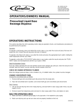
Typical CF-1522 Beverage Dispensing System
Important
Failure to follow these installation guidelines may
affect warranty coverage.
Beverage Dispensing System
Typical CF-1522
show the basic operation of the
This is a simplified schematic to
beverage system.
NOTE:
CF-1522
100
75
SYRUP
CO
2
CO
2
CO
2
SYRUP
60
Cylinder
Bag-In-Box
Carton
Syrup
Syrup Pump
BIB
Tap Water
Water from Coldplate
Carbonated Water
Water to Coldplate
Carbonator
Pump
Carbonator

Installation Instructions Section 2
2-2
Part Number 020002472 04/09
Pre-installation Checklist
When installing any system, first make sure the major components are available. Generally the major components
necessary for an installation are:
Pre-mix System:
B-I-B System also:
Post Mix System:
Figal system also:
CO
2
regulator set
Product connectors for Figal tank
Gas connectors for Figal tank
Beverage dispenser
Beverage tubing
CO
2
tank
Figal beverage tanks
Stepless (Oetiker) clamps
Chain for CO
2
tank
B-I-B connectors
B-I-B regulator set
B-I-B rack
B-I-B syrup boxes
CO
2
regulator set
Beverage dispenser
Beverage tubing
CO
2
tank
Carbonator
Stepless (Oetiker) clamps
Chain for CO
2
tank
Syrup connectors for Figal tank
Gas connectors for Figal tank
Figal syrup tanks

Section 2 Installation Instructions
Part Number 020002472 04/09 2-3
Bulk Syrup System also:
Double Check:
Also consider the location of the following items
before installation:
Unit Inspection
The Servend Drop-In is shipped in a heavy duty
corrugated carton with a wooden pallet. Inspect the
Drop-In for freight damage. If any damage is noticed,
stop immediately and contact your delivering freight
company. You must file a freight claim for your
equipment. Failure to do so can void any claims.
Servend is not responsible for any freight damage.
Syrup connectors for Bulk tank
Gas connectors for Bulk tank
Bulk syrup tanks
Do you have enough space to install the
dispenser?
Is the countertop level?
Can the countertop support the weight of the
dispenser plus the weight of the stored ice?
Water line
Drain
Power outlet
Heating and air conditioning ducts

Installation Instructions Section 2
2-4
Part Number 020002472 04/09
Unit Dimensions
Location
Avoid placing the dispenser near heat sources such as
radiators, ovens, refrigeration equipment and direct
sunlight.
MODEL A B C* D E F G H
CF-1522 44.38”
(112.8 cm)
38.38"
(97.5cm)
9.50"
(24.2 cm)
15.00"
(38.2 cm)
N/A 16.38"
(42.8cm)
22.00”
(55.9cm)
22.00"
(55.9 cm)
B
A
E
G
D H
C
F
!
Caution
Cutting the countertop may decrease its strength.
Counter should be braced to support the dispenser
countertop weight plus ice storage capacity and
weight of icemaker, if applicable.

Section 2 Installation Instructions
Part Number 020002472 04/09 2-5
Footprints
CF-1522
!
Caution
Cutting the countertop may decrease its strength.
Counter should be braced to support the dispenser
countertop weight plus ice storage capacity and
weight of icemaker, if applicable.
CF-1522 cut out width 15.25" (38.7 cm)
CF-1522 cut out depth 22.25" (56.5cm)

Installation Instructions Section 2
2-6
Part Number 020002472 04/09
Electrical
GENERAL
MINIMUM CIRCUIT AMPACITY
The minimum circuit ampacity is used to help select the
wire size of the electrical supply. (Minimum circuit
ampacity is not the beverage/ice machine’s running amp
load.) The wire size (or gauge) is also dependent upon
location, materials used, length of run, etc., so it must be
determined by a qualified electrician.
ELECTRICAL REQUIREMENTS
Refer to Machine Model/Serial Plate for voltage/
amperage specifications.
VOLTAGE
The standard voltage for CF-1522 dispensers is
120VAC-60Hz 1 Ph. A power cord is provided with
120VAC-60Hz models only. 220/240 Volts - 50 Hz - 1 Ph,
208/230 Volts - 60 Hz - 1 Ph are also available.
MINIMUM CIRCUIT AMPERAGE CHART
Optimum Ambient Conditions are between 50°F and
95°F (10°C and 35°C).
Grounding Instructions
This appliance must be grounded. In the event of
malfunction or breakdown, grounding provides a path of
least resistance for electric current to reduce the risk of
electric shock. This appliance is equipped with a cord
having an equipment-grounding conductor and a
grounding plug. The plug must be plugged into an
appropriate outlet that is properly installed and grounded
in accordance with all local codes and ordinances.
!
Warning
All wiring must conform to local, state and national codes.
Dispenser Voltage/Cycle
Circuit
Amps
CF-1522 120/60 2.4
Important
Due to continuous improvements, this information is
for reference only. Please refer to the dispenser
serial number tag to verify electrical data. Serial tag
information overrides information listed on this page.
!
Warning
Risk of electrical shock. Connect to a properly
grounded outlet only.
!
Warning
Improper connection of the equipment-grounding
conductor can result in a risk of electric shock. The
conductor with insulation having an outer surface
that is green with or without yellow stripes is the
equipment grounding conductor. If repair or
replacement of the cord or plug is necessary, do not
connect the equipment-grounding conductor to a
live terminal. Check with a qualified electrician or
serviceman if the grounding instructions are not
completely understood, or if in doubt as to whether
the appliance is properly grounded. Do not modify
the plug provided with the appliance — if it will not fit
the outlet, have a proper outlet installed by a
qualified electrician.

Section 2 Installation Instructions
Part Number 020002472 04/09 2-7
!
Warning
When using electric appliances, basic precautions
should always be followed, including the following:
a. Read all the instructions before using the
appliance.
b. To reduce the risk of injury, close
supervision is necessary when an
appliance is used near children.
c. Do not contact moving parts.
d. Only use attachments recommended or
sold by the manufacturer.
e. Do not use outdoors.
f. For a cord-connected appliance, the
following shall be included:
• Do not unplug by pulling on cord. To
unplug, grasp the plug, not the cord.
• Unplug from outlet when not in use and
before servicing or cleaning.
• Do not operate any appliance with a
damaged cord or plug, or after the
appliance malfunctions or is dropped or
damaged in any manner. Contact the
nearest authorized service facility for
examination, repair, or electrical or
mechanical adjustment.
g. For a permanently connected appliance —
Turn the power switch to the off position
when the appliance is not in use and before
servicing or cleaning.
h. For an appliance with a replaceable lamp —
Always unplug before replacing the lamp.
Replace the bulb with the same type.
i. For a grounded appliance — Connect to a
properly grounded outlet only. See
Grounding Instructions.

Installation Instructions Section 2
2-8
Part Number 020002472 04/09
Unit Installation
To properly install the Servend Drop-In, Use these
guidelines:
• Meet all local code requirements.
• Have a receptacle with the proper voltage at the
installation site for connection to the Drop-In.
• Completely unpack the Drop-In, removing all padding
and shipping retainers.
• Route the beverage tubing from the syrup racks to
the location of the Drop-In.
• Make all beverage connections, if necessary, at the
syrup racks.
• Mark the counter top with the appropriate cut out
opening.
• Check that the cut out location is approved by the
owner before any cuts are made in the counter top.
• Compare the marked cut out with the dispenser
chest size. Be sure you are going to make the proper
hole size.
• Cut the marked opening in the counter top.
• Place one block of wood on the left side of the
opening at the edge of the cut out. Place another
block of wood on the right side of the opening at the
edge of the cut out.
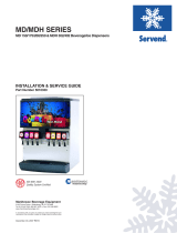
NOTE: When installing a CF-1522 in a stand it may be
necessary to turn the pump head on the pump deck to
allow room for water line connections. See figures 1 and
2 on this page for turning the pump head.
1. Loosen the clamp by turning the 5/16" screw.
2. Turn the pump to the position shown and secure in
place by retightening the clamp screw.
Important
The unit must be sealed to the counter to comply with
NSF requirements.
!
Caution
Cutting the countertop may decrease its strength.
Counter should be braced to support the dispenser
countertop weight plus ice storage capacity and
weight of icemaker, if applicable.

Section 2 Installation Instructions
Part Number 020002472 04/09 2-9
PLACING THE UNIT AND OPERATION SETUP
1. Set the Drop-In in place resting on the two blocks of
wood mentioned earlier.
NOTE: Servend has available hooks that fit into the door
stop holes. This allows for easier handling of the Drop-In.
2. Attach the drain lines to the drain connections at the
bottom rear of the chest. There is one drain for the
drain pan. Another drain fitting is provided for the ice
chest. These must be connected separately. (See
Purge Tube Routing)
3. Route the purge tube as described in the "Carb Tank
Purge Tube Routing" section
4. Connect the carbonator pump deck (power supply)
to the valve connection (if equipped) at the Drop-In.
The wires are marked appropriately. Check the
electric key switch on the side of the tower. The key
should be in the off (vertical) position.
5. The outside edge of the chest flange must be sealed
to the counter top. Apply a generous amount of
sealant to the underside of the outside edge of the
flange.
DETAIL "A"
Handles
(PN# 4340201)
D
R
A
I
N
P
A
N
D
O
O
R
ST
O
P
S
SEE DETAIL "A"
Wood Block Wood Block
Counter Top

Installation Instructions Section 2
2-10
Part Number 020002472 04/09
6. Carefully remove the two blocks of wood from under
the flange. The Drop-In will then sit flat on the
counter top.
7. Wipe excess sealant from around the outer portion
of the flange.
8. Check to be sure the entire flange edge is sealed to
the counter top.
9. Apply water and syrup pressure to the beverage
system. Check for leaks to the system. Repair any
leaks found.
10. Purge air from the carbonator tank. See "Purging Air
From The Carbonator Tank" below.
11. Pour about one gallon cold water into the chest.
Check for any drain line leaks. Repair any leaks
found.
12. Pour about one pint of cold water into the drain pan.
Check for any drain line leaks. Repair any leaks
found.
13. Install merchandiser to the unit. The cord must be
routed down the left side conduit. Connect cord to
power supply.
14. Plug power cord (from the carbonator motor) into the
unit power cord assembly.
15. Connect the power supply cord from the carbonator
deck box to the proper electric supply.
16. Turn the key switch for the valves to the “ON”
position.
17. Push each valve operator one at a time. Operate
each valve long enough to obtain both syrup and
water through the valve.
18. Fill the chest with ice. Allow the coldplate to chill the
beverage tubing inside the coldplate.
19. Clean your work area while waiting for the cold plate
to cool.
20. After the coldplate has completely chilled, operate
one valve for about 15 seconds. Take a temperature
reading of the beverage on the next 15 second draw.
If the sample drawn is 40°F or lower, go to the next
step. If the beverage is higher than 40°F, wait 10
minutes longer for the beverage to attain the proper
temperatures. Then repeat this step.
21. When the beverage achieves the proper
temperature, set the flow of the water first, then set
the flow of the syrup to achieve the ratio (brix)
recommended by the syrup supplier.
22. Wipe down the Drop-In and make final inspection of
the area.Incoming Water Supply requirements
NOTE: Manitowoc Beverage Equipment recommends
that a water shutoff valve and water filter be installed in
the incoming water supply line.
The incoming water source to the equipment shall be
installed with adequate backflow protection to comply
with applicable National, State, and local codes.
Water pressure should be a minimum of 45 psi or you
will starve the pump of water and damage it. The
maximum water pressure should be 55 psi or you will
affect the quality of the carbonation.
The carbonator pump should be located within 6 feet of
a 1/2 inch water source. A minimum 3/8 inch ID water
line must be used. Before connection the water source
should be flushed of approximately 5 gallons of water to
purge the system of any sediments, especially in areas
of new construction.
PURGING AIR FROM THE CARBONATOR TANK
1. Plumb unit as described in steps 1 - 8. Do not
energize the unit. Do not turn on the CO
2 to the unit.
2. Remove the splash panel and open the vent on the
carbonator pressure relief valve.
3. Turn on the water to the unit and fill the carbonator
with water. Close the vent on the carbonator
pressure relief valve when water begins to escape.
4. Follow the instructions in the manual for energizing
the unit.
5. Operate any valve to remove all the air from the
water lines.
Follow instructions in the manual for remaining unit set
up.

Section 2 Installation Instructions
Part Number 020002472 04/09 2-11
COLD CARB AND AMBIENT SYSTEM PRESSURES
1. Incoming tap water should be at a minimum static
pressure of 40 psi (2.758 bars) and a maximum of
55 psi (3.792 bars) with carbonator pump operating
(measured at inlet to pump).
2. BIB pressure gauge set for 60 psi (4.137 bars) or
according to your line run.
3. Carbonator Pressure gauge (Use Preset Regulator):
- Cold Carbonation set for 75 psi (5.171 bars).
- Ambient systems should be set at 90 psi (6.205
bars) to 105 psi (7.239 bars).
NOTE: If incoming dynamic water pressure is under 40
psi (2.758 bars), a water booster is recommended. If
incoming static water pressure is over 55 psi (3.792
bars), a water regulating valve is required.
PRE-MIX SYSTEM INSTALLATION
These installation steps are general. Each system and
installation is unique. You may have to modify these
instructions to your particular installation.
1. Lay out the system. Proper planning will eliminate
obstacles later in the installation.
2. Recheck the location to assure yourself the proper
electric, and drain lines are available.
3. Check to be sure you can route the beverage tubing
to the location.
4. If necessary, cut any holes necessary for utilities and
beverage tubing, or ice chest.
5. Place the beverage dispenser in the selected
location.
6. Place the CO
2 supply tank and the beverage Figal
tanks in the proper location.
7. Mark all beverage tube ends (both ends) with the
beverage name it is to carry.
8. Route the appropriate number and size beverage
tubes to the dispenser location.
9. Reading the dispenser plumbing diagram connect
the appropriate beverage tube to the appropriate
plumbing inlet.
10. Connect the beverage tubing to the appropriate
Figal tanks liquid outlet.
11. Connect the CO
2 lines from the tank to each Figal
tank gas inlet.
12. Open the CO
2 tank. Adjust the pressure regulator at
the CO
2 tank to 60 psi (4.137 bars) (diet drinks 40
psi (2.758 bars)).
13. Operate each valve at the dispenser until beverage
flows out in a steady stream. Do not be concerned
that the product foams excessively at this time.
14. Fill the ice chest with ice to cool the cold plate or
activate the cooling mechanism of the dispenser.
Allow the product to cool sufficiently.
15. Explain how to change a Figal tank and CO
2 tank to
the owner/operator.
PLUMBING DIAGRAMS
Plumbing Diagram And Flex Manifold Locations
Install the beverage tubing to the appropriate fittings.
Refer to the cold plate drawing on the back of the splash
panel for your individual set up. See the example below
of how your Drop-In may be hooked up.
NOTE: A check valve must be installed in the water
supply line 3 feet from the noncarbonated water
connection “PW”. Contact factory if not installed.
Back of Splash Panel

Installation Instructions Section 2
2-12
Part Number 020002472 04/09
CF-1522 4 Valve Plumbing
Install the beverage tubing to the appropriate fittings. Refer to the cold plate drawing on the front of the chest for your
individual set up. (See the example below of how your Drop-In may be hooked up.)
PRE-MIX PRESSURES
Normal pre-mix pressure regulators should be set at 60 PSI.
Diet pre-mix pressure regulators should be set at 40 PSI. If
you are experiencing high foaming, decreasing the
pressures may correct the problem. Spitting and popping
usually requires slightly increasing the pressures. Pre-mix
beverage valve pressures vary by type and manufacturer.
Please consult the manufacturer of the valves you are using
for specific instructions regarding operation of the valve.
CONVERSION FOR NON-CARBONATED FLAVOR
1. De-pressurize system.
2. Remove drain grid, splash panel and drainpan to access
insulated lines.
3. Cut carb water line (in tower) to valve to be converted
and cap.
4. Disconnect syrup line to valve being converted.
5. Plumb syrup circuit in coldplate to water side of valve
(flush syrup line first).
6. Plumb dedicated plain water line from water source to
coldplate inlet (syrup circuit converted for chilling water).
7. Run ambient syrup line into drop-in tower to syrup side
of valve.
8. Replace drainpan, splash panel and drain grid.
9. Pressurize system and verify system operation.
NOTE: Tapping into existing water line too close to the pump
deck can result in starving the valve when the carbonator
cycles. If a dedicated water line is not possible, tee into the
existing water line as close to the source as possible.
Cut / cap carb
water line
Re-plumb syrup
line to water side
of valve
Ambient syrup
line into unit and
to valve

Section 2 Installation Instructions
Part Number 020002472 04/09 2-13
STARTING YOUR BEVERAGE SYSTEM & DISPENSER
Upon completion of the beverage dispenser and / or system
installation, all tubing, dispenser, and system components
must be cleaned and sanitized prior to use.
NOTE: At installation equipment, dispensers, and tubing get
moved through many environments, dirt, dust, chases,
insulation, drywall, etc. It is an important procedure and best
practice to address cleaning to deliver the best quality drink
to your customer.
Clean and sanitize the water and syrup circuits according to
instructions provided in this manual. Clean and sanitize the
dispenser components according to instructions provided in
this manual. Consult and use local health codes if a
discrepancy occurs between this manual and your local
health codes.
Bag-in-Box (BIB) Start-up
All lines should be properly flushed and sanitized before
starting the unit. See Sanitizing Instructions
1. Connect each BIB connector to the appropriate BIB.
2. Gradually adjust the secondary regulator to 70 psi.
Never run a BIB pump without the BIB installed as the
pump could be damaged. Set final secondary regulator
pressure 70 -75 psi depending on the line size and the
distance of the run.
3. Operate each dispensing valve until the syrup flows
smoothly from the valve.
Adjust Syrup to Water Ratio (Brix) of Dispensed Product
1. Adjust water flow rate on each dispensing valve to 2.5
ounces per second.
2. Adjust dispensing valves for water-to-syrup ratio (brix)
as recommended by the syrup distributor.
INSTALL LABELS
Install flavor labels (some labels are provided) on the
dispensing valve covers.
CLEAN UP
Clean up all work areas. Dispose of all packing material,
excess tubing and trash properly.

/