Page is loading ...

614.00133.01
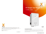
X3 Series User Manual
30.0KW/36.0KW
Solax Power Network Technology(Zhe jiang) Co,. Ltd.
(Solax Power Co,. Ltd)
Copyright Declaration
The copyright of this manual belongs to Solax Power Network Technology(Zhe jiang) Co,. Ltd.
(SolaX Power Co.,Ltd.). Any corporation or individual should not plagiarize, partitially or fully copy
(including software,etc.), and no reproduction or distribution of it in any form or by any means. All
rights reserved. SolaX Power Network Technology (Zhe jiang) Co.,Ltd. (SolaX Power Co.,Ltd.).
reserves the right of final interpretation.

Contents
1 Notes on this manual
1.1 Scope of Validity
1.2 Target Group
1.3 Symbols Used
03
03
03
2 Safety
2.1 Appropriate Usage
2.2 Important Safety Instructions
2.3 Explanation of Symbols
2.4 CE Directives
04
05
06
09
3 Introduction
3.1 Basic Features
3.2 Terminal of PV Inverter
3.3 Dimensions
10
10
11
4 Technical Data
4.1 DC Input
4.2 AC Output
4.3 Efficiency, Safety and Protection
4.4 General Data
5 Installation
5.1 UnPacking
5.2 Check for Transport Damage
5.3 Installation Precaution
5.4 Preparation
5.5 Installation Steps
5.6 Connections of The PV Power System
5.7 Run The Inverter
Contents
04
12
12
13
13
14
15
16
17
18
19
30

7 Troubleshooting
7.1 Trouble Shooting
7.2 Routine Maintenance
8 Decommissioning
8.1 Dismantling The Inverter
8.2 Packaging
8.3 Storage
8.4 Disposal
1 Notes on this Manual
1.2 Target Group
1.1 Scope of Validity
This manual is an integral part of inverter, it describes the assembly,
installation, commissioning, maintenance and failure search of the
below inverters. Please read it carefully before operating.
Note: “30.0” means 30kW. ”T” means “double” MPPT string. “D” means with
“DC Switch”, ”N” means without “DC Switch”.
Store this manual where it will be accessible at all times.
This manual is for qualifed electricians. The tasks described in this manual
only can be performed by quali?ed ele tricians.
1.3 Symbols Used
The following types of safety instructions and general information appear in
this document as described below:
DANGER!
“DANGER”indicates a hazardous situation which, if not avoided,
will result in death or serious injury
X3-30.0-T-D X3-36.0-T-D
X3-30.0-T-N X3-36.0-T-N
WARNING!
“Warning”indicates a hazardous situation which, if not avoided,
will result in death or serious injury.
.
CAUTION!
“Caution” indicates a hazardous situation which, if not avoided,
will result in minor or moderate injury.
NOTE!
“Note” provides tips that are valuable for the optimal operation
of your product.
Contects 1 Notes on this Manual
37
39
37
41
41
41
41
41
31
31
31
6InternetMonitoringFunction
6.1Connectandlogon
6.2Menustructure
6.3Internetoperation 32

04
1
A
Distribution
Box
Distribution
Box
Inverter
2 Safety
2.1 Appropriate Usage
The X3 Series is a PV inverter which converts the DC current of a PV
generator into AC current and feeds it into the public grid.
Surge protection devices(SPDs) for PV installation
Lightning can cause damage either from direct strike or from surges due to
a nearby strike.
Induced surges are the more likely cause of lightning damage in the
majority of installations, especially in rural areas where electricity is usually
by long overhead lines. Surge may be induced on both the PV array
conduction and the a.c cables leading to the building.
Specialists in lightning protection should be consulted during the end use
application. Using appropriate external lightning protection, the effect of a
direct lightning strike into a building can be mitigated in a controlled way,
and the lightning current can be discharged into the ground.
Installation of SPDs to protect the inverter against mechanical damage and
excessive stress include a surge arrester in case of a building with external
lightning protection system(LPS) when separation distance is kept.
To protect the d.c. system, surge suppression device(SPD type2) should be tted
at the inverter end of the d.c cabling and at the array, located between the
inverter and the PV generator, if the voltage protection level(VP) of the surge
arresters I s greater than 1100V, an additional SPD type 3 required for surge
protection for electrical devices.
To protect the a.c system, surge suppression devices(SPD type 2) should be tted
at the main incoming point of a.c supply(at the consumer’s cutout), located
between the inverter and the meter/distribution; SPD (test impulse D1)for signal
line according to EN 61643-21.
All d.c cables should be installed to provide as short runs as possible, and positive
and negative cables of the same string or main d.c supply should be bundled
together, avoiding the creation of loops in the system. This requirement fo short
runs and bundling includes any associated earth/bundling conductors.
Spark gap devices are not suitable to be used in d.c circuits as once conducting
they won’t stop conducting until the voltage across their terminals is typically
more than 30 volts.
2.2 Important Safety Instructions
Over-voltage protection with surge arresters should be
provided when the PV power system is installed.
The grid connected inverter is not ?tted with SPDs in
both PV input side and MAINS side.
WARNING!
Danger!
Danger to life due to high voltages in the inverter!
All work must be carried out by qualied eletrician.The
appliance is not to be used by children or persons with reduced
physical sensory or mental capabilities, or lack of experience and
knowledge, unless they have been given supervision or
instruction.Children should be supervised to ensure that they
do not play with the appliance.
Caution!
Danger of burn injuries due to hot enclosure parts!
During operation, the upper lid of the enclosure and the
enclosure body may become hot.
Only touch the lower enclosure lid during operation.
Caution!
Possible damage to health as a result of the effects of radiation!
Do not stay closer than 20 cm to inverter for any length of time.
2 Safety
gure1 Note:ForX3-36.0-T-N,whenexternaltransformerisrequired,technical
specicationshallberefferedtothedocumentprovidedbySolax.

Light color Meaning of the light
Blue
Yellow
Red
Yellow(icker)
The inverter is in normal state.
There are some problems,
but the inverter still can run normally.
There are some serious problems,
please inform your installer immediately.
The inverter is in a state of being monitored.
Symbol
06
4
WARNING!
WARNING!
Read all instructions, cautionary markings on the inverter, and all
appropriate sections of this manual before using this inverter.
Use only attachments recommended or sold by SolaX.
Make sure that existing wiring is in good condition and that wire is not
undersized. Do not operate the X3 Series inverter with damaged or
substandard wiring.
Do not disassemble the X3 Series inverter. It contains no user-serviceable
parts. See Warranty for instructions on obtaining service. Attempting to
service the X3 Series inverter yourself may result in a risk of electric shock
or re and will void your warranty.
Keep away from ammable, explosive materrials to avoid fe disaster.
The installation place should be away from humid or corrosive substance.
Authorized service personnel must use insulated tools when installing or
working with this equipment.
PV modules shall have an IEC 61730 class A rating.
Authorized service personnel must disconnect both AC and DC
Power from the X3 Series inverter before attempting any
maintenance or cleaning or working on any circuits connected to
the X3 Series inverter.
Note!
Grounding the PV generator.
Comply with the local requirements for grounding the PV
modules and the PV generator. SolaX recommends connecting
the generator frame and other electrically conductive surfaces
in a manner which ensures continuous conduction and ground
these in order to have optimal protection of system and persons.
Danger
Risk of electric shock!
Observe enclosed documentation
The inverter can not be disposed of together with the household waste.
Disposal information can be found in the enclosed documentation.
Don’t work on this inverter until it is isolated from both mains and
on-site PV generation suppliers
Danger to life due to high voltage
There is residual voltage in the inverter which needs 45 min to discharge.
Wait 45 min before you open the upper lid or the DC lid.
When using the product, please do remember the below information to avoid
the ?e, lightning or other personal injury
2.3 Explanation of Symbols
This section gives an explanation of all the symbols shown on the inverter
and on the type label.
Symbols on the Type Label
CE mark
The inverter complies with the requirements of the applicable
CE guildlines.
TUV certied
RCM remark
SAA certication
Beware of hot surface
The inverter can become hot during operation. Avoid contact
during operation
Danger of high voltages
Danger to life due to high voltages in the inverter!
Ensure input DC voltage≤Max. DC voltage. Over voltage may
cause permanent damage to inverter or other losses, which will
not be included in warranty! This chapter contains important
safety and operating instructions. Read and keep this Operation
Guide for future reference.
Symbols on the Inverter
table1 symbols on the inverter
table2 Symbols on the type label

08
Incorrect grounding can cause physical injury, death or equipment
malfunction and increase electromagnetic interference.
Make sure that grounding conductors is adequately sized as required by
safety regulations.
Do not connect the ground terminals of the unit in series in case of a
multiple installation. This product can cause current with a DC component,
where a residual current operated protective(RCD) or
monitoring(RCM)device is used for protection in case of direct or indirect
contact, only an RCD or RCM of type B is allowed on the supply side of this
product.
For United Kingdom
The installation that connects the equipment to the supply terminals shall
comply with the requirement of BS 7671.
Electrical installation of PV system shall comply with the requirements of BS
7671 and IEC60364-7-712.
No protection setting can be altered.
User shall ensure that the equipment is so installed properly, design and
operated to maintain at all times comply with the requirements of ESQCR
22(1)(a).
For Australia and New Zealand:
The installation of inverter must fulll Australia National Wiring rules
AS/NZS3100,AS/NZS4777.2 and AS/NZS5033.
The unit contains capacitors that remain charged to a potentially lethal voltage
after the MAINS and PV supply has been disconnected.
Hazardous voltage will present for up to 45 minutes after disconnection from
power supply.
Never touch either the positive or negative pole of PV connecting device.
And never ever touch both at the same time.
CAUTION-RISK of electric shock from energy stored in capacitor, never work
on the solar inverter coupler, the MAINS cable, PV cables or the PV
generator when power is applied. After switching o ffthe PV power and
Mains, always wait for 15 minutes to let the intermediate circuit capacitors
discharge before you unplug DC input and MAINS couplers.
When access to internal circuit of solar inverter, it is very important to wait
45 minutes before working on power circuit or demounting the electrolyte
capacitors inside the device. Do not open the device by hand since the
capacitors require this long to discharge sufficiently!
Measure the voltage between terminals UDC+ and UDC- with a multi-
meter(impedance at least 1Mohm) to ensure that the device is discharged
before beginning work(35VDC) inside the device.
2.4 CE Directives
This chapter follows the requirements of the European low voltage directives,
which contains the safety instructions and conditions of acceptability for the
endues system, which you must follow when installing, operating and
servicing the unit. If ignored, physical injury or death may follow, or damage
may occur to the unit. Read this instructions before you work on the unit. If
you are unable to understand the dangers, warnings, cautions or instructions,
please contact an authorized service dealer before installing. Operating and
servicing the unit.
The Grid connected inverter meets the requirement stipulated in Low
Voltage Directive (LVD) 2014/35/EU and Electromagnetic Compatibility (EMC)
Directive 2014/30/EU. The unit is based on:
EN 62109-1:2010 ; EN 62109-2:2011 ; IEC 62109-1(ed.1) ; IEC62109-2(ed.1)
EN 61000-6-3:2007+A:2011 ; EN 61000-6-1:2007 ; EN 61000-6-2:2005
In case of installation in PV system, startup of the unit (i.e. start of designated
operation) is prohibited until it is determined that the full system meets the
requirements stipulated in EC Directive (2014/35/EU,2014/30/EU, etc.)
The grid connected inverter leave the factory completely connecting device
and ready for connection to the mains and PV supply ,the unit shall be
installed in accordance with national wiring regulations. Compliance with
safety regulations depends upon installing and conguring system correctly,
including using the specied wies. The system must be installed only by
professional assemblers who are familiar with requirements for safety and
EMC. The assembler is responsible for ensuring that the end system complies
with all the relevant laws in the country where it is to be used.
The individual subassembly of the system shall be interconnected by means
of the wiring methods outlined in national/international such as the national
electric code (NFPA) No.70 or VDE regulation 0107.
WARNING!
High leakage current!
Earth connection is essential before connecting supply.
PE Connection and leakage current
The end-use application shall monitoring of the protective conductor by
residual current operated protective device(RCD)with rated fault current
Ifn≤100mA which automatically disconnects the device in case of a fault.
DC differential currents are created (caused) by insulation resistance and
through capacities of the PV generator. In order to prevent unwanted
triggering during operation, the rated residual current of the RCD has to be
min 100mA.
The device is intended to connect to a PV generator with a capacitance
limit of approx 700nf.

10
Earth Fault Alarm(Optional)
3 Introduction
3.1 Basic Features
Congratulations on your purchase of a X3 Series inverter from SolaX. The X3
inverter is one of the nest inverter on the market today, incorporating
state-of-the-art technology, high reliability, and convenient control features.
Advanced DSP control technology.
Utilize the latest high-efficiency power component.
Optimal MPPT technology.
- Two independent MPPT technology.
- Wide MPPT input range.
Advanced anti-islanding solutions.
Anti-theft protection.
IP65 protection level.
Max efficiency up to 98.6%,EU efficiency up to 98.3%.
THD <2%
Safety&Reliability: transformerless design with software and hardware
protection.
Friendly HMI.
- LED status indications.
- RS485, dry contact , LAN communication and WiFi interface.
- USB upgrade.
- PC remote control.
3.2 Terminal of PV inverter
WARNING!
3.3 Dimensions
ADC Switch(optional)
BDC Connector area
C
Pocket WiFi (Optional)
D
Waterproof Lock Valve
E
F
G
H
AC Connector
680 mm
255 mm
605 mm
Only qualied electricians can operate the connection.
Cables Opening for RS485 connection
USB for upgrade
ILAN Connector
JGround screw
ABC
EF
G
H
I
DE
J
ON
OFF
AC
WiFi
LAN E.F Alarm
RS485
Upgrade
PV1 PV2
-
+
-
+
gure2
gure3
table3 Terminal of PV inverter

4 Technical Data
4.1 DC Input
4.2 AC Output
X3-30.0-T-D/
X3-30.0-T-N
X3-36.0-T-D/
X3-36.0-T-N
1000
750
X3-30.0-T-D/
X3-30.0-T-N
X3-36.0-T-D/
X3-36.0-T-N
Max. DC input voltage(V)
Nominal input voltage(V)
Max. DC input current(A)
DC input power(KW)
Max. short-circuit current(A)
MPPT voltage range(V)
MPPT voltage range
@full load(V)
Output voltage of starting
grid connection(V)
No. of MPP inputs
No. of strings per MPP input
DC switch
640
34/34
20/20 23/23
48/48
280-950
480 580
300
2
4
Optional
Rated output power(W)
Max. apparent AC power(VA)
Nominal frequency(HZ)
Frequency range(HZ)
AC nominal current(A)
Max. output current(A)
Displacement power factor
THD
DC component
30000(29800 for AU) 36000
30000 36000
nominal voltage(V) 220/230 277
50/60
45-55/55-65
3*45
3*48
0.8leading...0.8lagging
2%
<0.5%
4.3 Efficiency, Safety and Protection
X3-30.0-T-D/
X3-30.0-T-N
X3-36.0-T-D/
X3-36.0-T-N
Max. efficiency
Euro efficiency
MPPT efficiency
Safety & Protection
Over/under voltage protection
DC isolation impedance
protection
Ground fault protection
Grid monitoring
Grid fault current monitoring
DC injection monitoring
Back feed current monitoring
Residual current detection
Anti-island protection
Over load protection
Over heat protection
98.60% 98.60%
98.30%
99.90%
98.30%
99.90%
YES
YES
YES
YES
YES
YES
YES
YES
YES
YES
YES
4.4 General Data
X3-30.0-T-D/
X3-30.0-T-N
X3-36.0-T-D/
X3-36.0-T-N
-20...+60(derating at 45)
0%...95%
<4000m
<50dB
Wall-mounted
Ⅱ
No-isolation
RS485/Dry contact/Lan/Wifi(Optional)
Chrome/Safari
Dimension(W/H/D)(mm)
Weight(kg)
Dimension of packing
(W/H/D)(mm)
Degree of protection
Operating temperature range
(℃)
Operating humidity range
Altitude
Noise level
Fixed type
Degree of protection
Isolation type
Communication interface
Supported browser
64
IP65
Night-time consumption <1W
Standard Warranty 5 years(10 years optional)
4 Technical Data 4 Technical Data
12
Gross Weight(kg)
680*605*255
740*862*397
72
table4 DC input
table5 AC output
table6
table7
Backfeedcurrenttothearray(A)0
Inrush current(A)
Max output fault current(A)
Overcurrent protection(A) 100
85
75

OP
1
O
P
Drycontactterminal(Optional)
Rs485sealingconnector
5 Installation
5.1 Unpacking
Open the package and pick the product, check that if there is any distortion
or impaired during the transportation. Meanwhile, check that if the relating
accessories and the materials are here, you can see the accessories list in the
table.
The instruction manual is an integral part of the unit and should therefore
be read and kept carefully.
It is recommended that the packaging should not be removed until the unit
is located in the installation site.
5.2 Check for transport damage
Check if the X3 Series inverter has some visible external damage, such as
cracks in the housing or display, please contact with your dealer if you nd
any damage.
5 Installation 5 Installation
14 15
X3 Series User Manual
30KW/36KW
FH
I
E
M
G
X3 Series 30KW/36KW
JKLI
X3 series inverter
Quick installation guide
Positive DC pin contact8
Negative DC pin contact
8
AC terminal
5
Pocket wi(optional)
Male DC connectors
Female DC connectors
Bracket
Warranty card
User manual
Expansion tubes
Expansion screws
N
Earth terminal
N
8
8
8
8
table8

16
No direct sunlight No rain exposure No snow lay up Direct sunlight Rain exposure Snow lay up
5.3 Installation precaution
5.4 Preparation
The X3 series inverter is designed for outdoor installation(IP65).
Make sure the installation site does not fall into none of the following
conditions:
Do not install the inverter in direct sunlight.
Do not install the inverter on ?ammable constru tion material.
Do not install the inverter in areas where highly ammable mateials are
stored.
Do not install the inverter in potentially explosive areas.
Do not install the inverter in the cool air directly.
Do not install the inverter near the television antenna or antenna cable.
Do not install the inverter in higher than the altitude of about 4,000m
above sea level.
Do not install the inverter during periods of precipitation of high humidity
(>95%), moisture trapped within the location may cause corrosion and
damage to the electric components.
Install the inverter in a location that maintains an ambient air temperature
which is less than 45℃, that is to maintain a safe internal component
temperature, the inverter reduce power if the ambient air temperature
exceeds 45℃
The inverter should be installed in a location that is not accessible for
children.
The inverter emits a slight vibrating noise when operating, this noise is
normal and no effect on performance.
The slope of the wall should be within ±5°
Keep the inverter far away from the seawater.
The inverter is heavy, ensure the mounting place is strong enough to hold
the weight of the inverter .
If you install the inverter in a cabinet, closet or other small enclosed area,
sufficient air circulation must be provided in order to dissipate the heat
generate by the unit.
Please avoiding direct sunlight, rain exposure, snow lay up when installing.
Below tools are needed before installation.
Installation Tools: crimping pliers for binding post and RJ45, screwdriver,
manual wrench,Φ8 driller and rubber hammer.
Lifting and Handling
During lifting procedures ensure that the unit is ?mly secured to avoid the
risk of accidental tipping or dropping.
Parts serving for support or immobilization of unit shall be designed and
manufactured so as to minimize the risk of physical injuries and accidental
loosening of xing.
Ensure that the method of lifting will not allow the unit to slip from chains
and slings or turn-over or slide from lifting devices.
Transportation must be carried by specialized person (truck operators,
hook-up personal), equipped with the necessary protection
equipments(overalls, safety shoes, protective gloves, helmets, goggles)
Do not walk or stand beneath or in the proximity of the load.
Avoid sudden movements and jolts when unloading and positioning the
unit. Internal handing procedures must be conducted with care. Do not
exert leverage on the components of the machine.
If the unit is not balanced apply ballast. Any protruding parts should not
be supported by hand.
The inverter should be installed so that the operating panel shall be easily
accessible easy access to the electrical power connection point.
Accessible for maintenance and repair work.
The unit is heavy. Do not lift it alone.
gure4
gure5
gure6
The wall hanging the inverter should meet conditions below:
1.solid brick/concrete, or strength equivalent mounting surface;
2.Inverter must be supported or strengthened if the wall’s strength isn’t
enough(such as wooden wall, the wall covered by thick layer of decoration)

5.5 Installation steps
Step2:Hang the X3 inverter onto the wall bracket.
Transporting the inverter need at least 2 persons, each one needs to
use the handles at the both sides of the inverter each.
Hang the X3 inverter onto the bracket, make sure the support on the
bracket is xed well with the inverter.
5.6 Connections of the PV power system
PV String
WARNING!
WARNING!
WARNING!
The X3 Series inverters has two input areas”A”and “B”,each with its own MPPT
tracker, can be connected in series into 2-strings PV modules. Please select
PV modules with excellent function and reliable quality. Open-circuit
voltage of module arrays connected in series should be less than Max. DC
input voltage; Operating voltage should be conformed to MPPT voltage
range.
Step1: Screw the wall bracket on the wall
Use the wall bracket as a template to mark the position of the six holes.
Drill holes with φ10 driller carefully, make sure the holes are deep enough for
install and tight the expansion tubes.
Install the expansion tubes in the wall, and screw the wall bracket using the
screws in the screw package.(φ10 driller.torque: 2.5±0.2Nm)
Step2
Step1
Loading capacity and hardness of the supporting surface, load rating of
mounting bracket should be at least four times the weight of the devices
according to IEC 62109-1 and supporting characteristic will be impaired by
wear, corrosion, material fatigue or ageing. This should be calculated by
inspection of the design data of supporting material and consulting
construction engineer.
PV module voltage is very high which belongs to dangerous
voltage range, please comply with electric safety rules when
connecting.
When the photovoltaic array is exposed to light, it supplies a DC
voltage to the PCE.
When there is something wrong with the modules arrays.
Modules can be connected with inverter only after eliminating
these problems.
Danger!
DangertolifeduetohighvoltagesonDCconductors.
whenexposedtosunlight,thepvarraygeneratesdangerousDC
voltagewhichispresentintheDCconductors.TouchingtheDC
conductorscanleadtolethalelectricshocks.
CoverthePVmodules.DonottouchtheDCconductors.

21
20
NOTE!
NOTE!
Input A Input B
DC
AC
DC
AC
X3-30.0-T-D/
X3-30.0-T-N
X3-36.0-T-D/
X3-36.0-T-N
The X3 with 2 MPP trackers area: A and B.
Area A with 4 strings input, area B with 4 string input.
The following requirements of PV modules need to be applied
for each input are:
Some type Some quantity Identical alignment Identical tilt
480~800 580~850
Please use PV cable to connect modules to inverter. From junction box to
inverter voltage drop is about 1-2%. So we suggest the inverter install near
PV module in order to save cable and reduce DC loss.(No longer than 30m)
Please do not make PV positive or negative ground!
Use multi-meter to measure module
array voltage.
Check the PV+ and PV- from the PV
string combiner box correctly. Make sure
the PV+ and PV- connected correctly.
Connection Steps
a) Turn off the DC switch.
b) Choose 12AWG wire to connect the PV module.
c) Trip 6mm of insulation from the wire end.
d) Separate the DC connector as below.
e) Insert striped cable into pin contact and ensure all conductor strand are
captured in the pin contact.
f ) Crimp pin contact by using a crimping pliers. Put the pin contact with
striped cable into the corresponding crimping pliers and crimp the contact.
(torque:1.2±0.1Nm)
g) Insert pin contact through the cable nut to assemble into back of the male
or female plug. When you feel or heard a “click” the pin contact assembly is
seated correctly.(torque:1.2±0.1Nm)
6.0 mm
12AWG
trip length
plug pin contact cable nut
h) Tight the DC connector.
a. Slide the cable nut towards the back shell.
b. Rotate the cable nut to secure the cable
Max. DC input voltage(V)
MPPT voltage range
(fullload)(V)
1000
-
+
DC1
gure7
gure8
gure9
gure10
gure11
gure12
gure13
table9

Connection
type
Stripping
length
WARNING!
AC Output
WARNING!
X3 Series inverters are designed for three phase grid. Voltage range is from
480V±10%, according to different countries. The typical frequency is
50HZ.Other technical requests should comply with the requirement of local
public grid. For the terminal and cable design, please follow below
requirement.
X3-30.0-T-D/
X3-30.0-T-N
X3-36.0-T-D/
X3-36.0-T-N
50A
Check the grid voltage and compare with the permissible voltage
range(see technical data).
Disconnect the circuit-breaker from all the phases and secure against re-
connection.
Trip the wires:
a. Trip all the wires to 52.5mm and the PE wire to 55mm.
b. Use the crimping pliers to trip 12mm of insulation from all wire ends as
below.
1.
2.
3.
Insert striped cable into AC pin contact and insure all conductor strands
are captured in the AC pin contact. Compress the AC pin contact’s head
by using a crimping pliers and compress tightly.
Separate AC cable gland , and insert the AC wire into the separate parts
.
4.
5.
6.Insert the ve wies into appropriate place in the AC terminal block
(R-R, S-S, T-T, N-N, PE-PE).
Before connecting, disconnecting the connection between solar
generator and inverter and locked it to the open position during
installation. Place a warning sign” do not turn on maintenance in
progress” on the external disconnect switch when it is shut down,
and make sure that on-o ffremote controls are inhibited.
Must comply with the connection requirement of your
distribution grid.
Cable and Micro-breaker recommended
Incorrect Connection between Load and Inverter
Micro-breaker should be installed between inverter and grid, any loads
should not be connected with inverter directly.
Connection steps
2
Cable(Cu) (mm)
Micro-breaker(A)
23
2
≥16mm
gure14
gure15
gure16
gure17
table10

Note 2:Fuses must be approved by Notied Body.
Inverter is not provided galvanic isolation from the mains to the PV array,
feedback current to the array is63A/250VACbased on the fuse provided in
the mains. Also in the worst case the reverse current comprises the sum of
the short-circuit currents of all intact lines.
The direct current(DC) circuit breaker or fuse between each solar generator
and inverter shall be provided based on solar inverter input ratings. Select
DC cables based in the above inverter and ISC PV rating and Vmax ratings.
7:Screw down the screws on the terminal block. Connect the terminal
block.
8:Tight the connection of the cable gland.
9:Install the cover of the inverter.
Selection of Fuses and Cables
Main cable(AC line cable)shall be short circuit protected and thermal
overload protected.
Always t the input cable with fuse. Normal gG(US:CC or T)fuses will protect
the input cable in short circuit situation. They will also prevent damage to
adjoining equipment.
Dimension the fuses according to local safety regulations, appropriate input
voltage and the related current of the solar inverter.
AC output protected by external fuse(gG rated current 50A/600VAC)provide
in all live connections to the AC supply.
The rated short circuit breaking capacity of the above protective device
shall be at least equal to the prospective fault current at the point of
installation. See section technical data of this manual details.
AC output cable: Cu ambient
2 2
;R, S, T, N+PE, 4*16.0mm+6.0mm @40℃
temperature with a max length of 5m, with operating time of the fuses is
less than 5 seconds, installation method B2 according to EN60204-1:2006,
annex D: cable in conduit cable trunking system, number of loaded circuit
only one. Use H07RNF(cord designation 60245 IEC66) for an ambient
temperature of 40 or less and use 90 wire for ambient temperature ℃ ℃
between 40 and 60℃ ℃.
Note 1: For condition differing form those mentioned above, dimension the
cables according to local safety regulations, appropriate input voltage and
the load and the load current of the unit.(You can choose a thicker cable
but the fuses must rated according to the cable.)
NOTE! 2
If the AC cable you choose is 16mm or larger, you need to
break the connection between the two rubber rings which
make up the rubber insert as below.
Communication interface
This product has a series communication interfaces, besides WiFi port , Lan
port, RS485&Dry contact and USB for upgrade are extend ports for human
and machine communication. Operating information like output voltage,
current, frequency, fault information etc, can be delivered to PC or other
monitoring equipments via these interfaces.
This inverter provides a WiFi port which can collect information from
inverter including status, performance and updating information to
monitoring website via connecting Pocket WiFi( purchase the product from
supplier if needed)
WiFi connection(optional)
Connection steps:
1.Plug the Pocket WiFi into “WiFi” port at the bottom of inverter.
2.Connect the wi with outer.
3.Set the station account on the solax web.(Please check the Pocket WiFi
user manual for more detail)(torque:0.6±0.1Nm)
Earth Connection
Screw the ground screw with allen wrench shown as follow.
(φ4 hexagon wrench.torque:1.5±0.2Nm)
gure18
gure19
gure20

26 27
RS485&Dry contact
1.Prepare two RJ45 connectors and a communication cable.
2.Trip the insulation from the communication cable.
3.Insert the communication cable into the RJ45 connector following the PIN
denition rule.
4.Crimp the RJ45 connector with the crimping plier.
5.Repeat the above steps to x the other head of the communication cable.
6.Insert one side of the cable into the LAN port on the inverter, and the
other side of the cable into the router or into the PC if you want to set the
parameters.
Connection steps
LAN communication is one standard communication interface. It transmits
the data between the router and X3 Series inverters in the local area
network. User can set the parameters with specialized software provided by
SolaX.
The pin denition of the connector is as below:
LAN Communication
a(2). RS485 Communication
RS 485 is one standard communication interface which can transmit the
real data from inverter to PC or other monitoring equipments. RS 485
communication shares the terminal block with X-NFI, and the denition is
as below.
Connection steps
1:Open the cover on the inverter.
2:Separate the Rs485 cable gland.
Function TX+ TX- RX+ RX-
Body of cable gland
Seal Cable nut
1......................................12
3: Trip the insulation from the wire ends.
4: Insert the wire into the separate parts as following:
5:Screw down the screws on the terminal block. Connect the terminal
block following the PIN denition rule.
6:Tight the connection of the cable gland.
Slide the seal to the body of the cable gland, insert the seal into the
body of the cable gland.
Slide the cable nut to the body of the cable gland, rotate the cable nut
to tight the connection.
a.
b.
7:Install the cover of the inverter.
a(1). X-NFI(Optional)
X-NFI is integrated with meter, it can control the output and reduce the
power of inverter, to assure the redundant power will not feed into Grid, X-
NFI communication use terminal block on the communication board in the
inverter.
Please refer to the X-NFI user manual for details.
gure21
gure22
gure23
gure24
gure25
table11
table12
PIN
Definition
1 3 4 5 6 7 8
GND 485_A
2
485_B 485_A 485_B NFI_B NFI_A
GND GND
910 11
NFI_B NFI_A
GND
12
unused unused unused unused

Pull off the U-disk,and the inverter will be restarted. Please contact your supplier
if the ARM upgrading is failed.
*note: Please do not pull up the U-disk if the DSP upgrading is failed. The system
will keep upgrading until it is successful.
b. Dry contact(Optional)
Connection steps
The connection steps are the same as the steps of RS485 connection steps.
Earth Fault Alarm(Optional)
4
The earth fault alarm is the additional detection, as required by AS 4777.2
and AS/NZS 5033, it will give an alarm once the earth impedance of the PV
arrays is more than 33KΩ .
PIN
De?nition
1 2 3 4
DRM4
5 6
DRM1 DRM2 DRM3 3.3V DRM0
1...................6
Dry contact is provided to give a remote monitor and remote control. The
remote monitor function provides an indication on the inverter’s working
status. The remote control function provides a contact signal to operate the
inverter. The dry contact communication use terminal block on the
communication board in the inverter. The PIN denition is as below
Note:onlyDRM0issupported.
.
Make sure the directory is in accordance with above form
strictly! Do not modify the program le name ! Or it may
cause the inverter doesn’t work anymore !
The inverter will alternately ash blue and yellow(icker) light about 15 times later,
automatically check if the device is needed to be updated. If necessary, the
light on the inverter will show the updated process, specic meaning of the
light sees the table.
3) ARM update(need several seconds)
blue red
yellow yellow
(icker) update level
light state
(bright√
and
not bright×)
25%
√× × ×
√ √ ×× 50%
√ √ √ × 75%
√√√ √ 100%
After ARM update, if the USB disk is still on the inverter, the inverter will also
alternately ash blue and yellow(icker) light about 15 times later, automatically
check whether the DSP needed be updated or not. The process is the same
as the ARM update process.
4) DSP update(need several minutes)
During updating, please turn off the DC switch or disconnect
the PV connector, then reinsert the U-disk.
28 29
5Upgrade
User can update the inverter system through an U-disk.
2) Make sure the DC switch is off and the AC is disconnected with grid.
Unscrew the waterproof lid, then insert U-disk into the “Upgrade” port
on the bottom of the inverter. Then turn on DC switch or connect the
PV connector.
1) Pleasecontactourservicesupporttogettheupdatele,andextractitinto
yourU-disk as follow
Make sure the input voltage is more than 200V (in good
illumination condition), or it may result in failing during updating.
“update\ARM\618.000 _X _ARM_Vx.xx_xxxxxxxx.usb”;83.00 330K
“update\DSP\618.00081.00_X330K_DSP_Vx.xx_xxxxxxxx.hex”.
Upgrade Steps:
Note: Vx.xx is version number, xxxxxxxx is le completion date.
5) After the upgrade is complete, please remember to turn off the DC
switch or disconnect the PV connector, then pull off the U-disk, screw
the waterproof lid.
gure26
table13
table14

Lan
router. )
3.Chooseuser,typeintheinitialpassword:123456.
1.Connectthecomputertotheinverterbyanetworkcable.
5.7 Run the inverter
WARNING!
NOTE!
Inverter will start automatically when PV panels generate enough energy.
Check the status of signal light, the LED should be green.
If the green light is not on, please check the below:
- All the connections are right.
- All the external disconnect switches are closed.
- The DC switch of the inverter is in the “ON” position.
Power to the unit must be turned on only after installation work
has been completed. All electrical connections must be carried
out by qualied personnel in accodance with legislation in force
in the country concerned.
Above steps is for the regular start up of the inverter. Please set
the inverter if it is the rst time to stat up.
Start inverter after checking all below steps:
Start inverter
6 Internet monitoring function
a) Check that device is fixed well on the wall.
b) Make sure all the DC breakers and AC breakers are disconnected.
c) AC cable is connected to grid correctly.
d) All PV panels are connected to inverter correctly, DC connectors
which are not used should be sealed by cover.
Turn on the external AC and DC connectors.
Turn on the DC switch to the “ON”position.
6.2Menustructure
6.1Connectandlogon
Note:Thepartinthedashedframeisonlysetbytechnicianandtheinstaller
with the installer password.
6 Internet monitoring function
gure27
gure28 Menu structure
ErrorLog
Advance
Information
Status
Measure
Yield Energy Yield
Inverter Status
Run Mode
SafetyType
powerFactor
AdjustParameter
Password
Function Setting
Safety Parameter Setting
Safety Type
Protection Value
CommAddr
Time Setting
Program Version
Energy control
Equipment only to be used for the purpose outlined by SolaX.
Status
1)Measure
It shows the information of Work Mode, ACinput, DCinput and PVstatus.
6.3Internetoperation
2.Please set static IPaddress:192.168.1.**(range:0~256), open the browser
(Chrome/Safari), input IP address: 192.168.1.13 (Please input the dynamic
IP address from the router if the inverter connects to a computer via a

2)Yield
Yielddisplaysthegeneratedpower
3)InverterStatus
Itincludesinformationoftheinverter:temperature,FanStatus,SPD
StatusandCommunicationStatus.
Errorlog
Itdisplaystheerrorinformationhappenedwiththeinverter.
Advance
1)RunMode
Onlycaninstallerortechniciansettheparameters.
6 Internet monitoring function6 Internet monitoring function
32 33
Reactivepowercontrol,Reactivestandardcurvecosφ=f(P)ForVDEARN4105,
curvecosφ=f(P)shouldrefertocurveA.defaultvaluesofsettingareasshownincurveA.
ForE8001,curvecosφ=f(P)shouldrefertocurveB.defaultvaluesofsettingareas
shownincurveB.
gure29
gure30
gure32
gure31
Reactivepowercontrol,ReactivestandardcurveQ=f(V)
0.9
0.9
Upperlimit
capactive inductive
f(P)
Lowerlimit
PowerLower
PowerUpper
curveA
0.3
0.7
0.9
0.9
Upperlimit
capactive inductive
f(P)
Lowerlimit
PowerLower
PowerUpper
curveB
0.3
0.7
0.2
0.8

2)SafetyType
Safetystandardcanbesetin"SafetyType".Accordingtodifferentcountries
andgridtiedstandards.Pleaseaccordingtotherequirementoflocalgrid
tosettheparametersoftheprotectionvalue.ForAustralia,pleasechose
4777(19)(thedefaultisAS4777).
3)SafetyParameter
ThisisonlyforAustralia,installerortechniciancansetthoseparameters.
4)Password
Theusercansetnewpasswordhere.
Information
Theusercansetthecommaddressandtime,checktheinformationof
theprogramversion.
6 Internet monitoring function6 Internet monitoring function
34 35
Q
V
Qmax
-Qmax
V2sV1s
V1iV2i
V2i=0.90Vn
V2s=1.10Vn
V1s=1.08Vn=QuVlowRate
V2i=0.92Vn=QuVlowRate
Parameter Setting Min~Max Description
Vpv_Start(V)
T_Start(S)
Vac_Min(V)
Vac_Max(V)
VacMinSlow(V)
VacMaxSlow(V)
PVstartupvoltage200V~800V***X0.1
Timetoconnectgrid
15Sec~300Sec
***X1
Minimumoperationalgridvoltage(stage2)
100V~300V
***X0.1
Maximumoperationalgridvoltage(stage2)
200V~400V
***X0.1
Minimumoperationalgridvoltagestage1(Slow)
Maximumoperationalgridvoltagestage1(Slow)
***X0.1
***X0.1
100V~400V
200V~400V
Fac_Min(Hz)
DCI_Limit(mA)
40Hz~70Hz***X0.01
Minimumoperationalgridfrequencystage1(Slow)
Maximumoperationalgridfrequencystage1(Slow)
***X1 20mA~2000mA
Minimumoperationalgridfrequency(stage2)
Maximumoperationalgridfrequency(stage2)
Fac_Max(Hz) ***X0.01 40Hz~70Hz
Fac_Min_Slow(Hz)
Fac_Max_Slow(Hz)
40Hz~70Hz***X0.01
***X0.01 40Hz~70Hz
MaximumlimitofDCinjectioncurrent
Parameter Setting Min~Max Description
gure33
gure34
gure35
gure36
gure37
table15 Parameter description

table16 Diagnosis and solution of faults-2
UVP_AC
BUS_UBALANCE
OFP_AC
UFP_AC
OVP_Boost
Relay fault
-DisconnectPV+andPV-,reconnectthe
-Or seek help form us, if can not go back to normal state
Boost over votage
-DisconnectPV+andPV-,reconnectthe
-Or seek help form us, if can not go back to normal state
7 Troubleshooting
7.1 Trouble Shooting
This section contains information and procedures for solving problems with
the X3 series inverters, and provides you with trouble shooting tips to
identify and solve most problems that could occur with the X3 series
inverters.
This section will help you narrow down the source of any problem you may
encounter. Please read the following troubleshooting steps.
Check the light of the inverter or the Fault Codes on the monitoring
website. Please record it before doing anything further if a message is
displayed.
Attempt the solution indicated in below table.
When red light is on, the faults will be probability as below:
7 Troubleshooting 7 Troubleshooting
36 37
table16 Diagnosis and solution of faults-1
OCP_AC
OCP_Boost
UnRevover_RelayFault
PVConfigset_Wrong
SampleConsistentFault
Thedetectioncircuitfault
OVP_BUS
-DisconnectPV+andPV-,reconnectthe
-Or seek help form us, if can not go back to normal state
AC over current detected
-DisconnectPV+andPV-,reconnectthe
-Or seek help form us, if can not go back to normal state
PV connection fault
-DisconnectPV+andPV-,reconnectthe
-Or seek help form us, if can not go back to normal state
Boost over current
-DisconnectPV+andPV-,reconnectthe
-Or seek help form us, if can not go back to normal state
BUS over voltage
-DisconnectPV+andPV-,reconnectthe
-Or seek help form us, if can not go back to normal state
Relay fault
-DisconnectPV+andPV-,reconnectthe
-Or seek help form us, if can not go back to normal state
Grid_Lost_Fault
Current_Sensor_Fault
EEPROM_WR_Fault
GFCI_Device_Fault
OVP_AC
Current sensor fault
-DisconnectPV+andPV-,reconnectthe
-Or seek help form us, if can not go back to normal state
EEPROM reading or writing fault
-DisconnectPV+andPV-,reconnectthe
-Or seek help form us, if can not go back to normal state
Leakage current detection deivce Fault
-DisconnectPV+andPV-,reconnectthe
-Or seek help form us, if can not go back to normal state
Grid voltage or frequence is out of range or not present at all
-System will reconnect after the utility is back to normal
-Or seek help form us, if can not go back to normal state
Over voltage in AC side
-DisconnectPV+andPV-,reconnectthe
-Or seek help form us, if can not go back to normal state
table16 Diagnosis and solution of faults-1
The BUS not balance
The grid frequency is over limit
-If this happens frequently,please contact with the grid Corp,
get the password to set the value,(VDE4105)
The grid frequency is under limit
-If this happens frequently,please contact with the grid Corp,
get the password to set the value,(VDE4105)
/