SolaX Power X1-X3-EVC Series Installation guide
- Type
- Installation guide
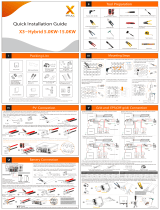
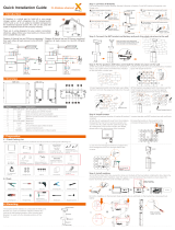
SolaX Power X1-X3-EVC Series is a versatile EV charger, suitable for both commercial and residential use. With a charging capacity ranging from 7.2kW to 22kW, it can quickly and efficiently charge electric vehicles. It supports both single-phase and three-phase power input, providing flexibility in installation. Additionally, it features a built-in communication module, allowing for remote monitoring and control through the SolaXCloud app.
SolaX Power X1-X3-EVC Series is a versatile EV charger, suitable for both commercial and residential use. With a charging capacity ranging from 7.2kW to 22kW, it can quickly and efficiently charge electric vehicles. It supports both single-phase and three-phase power input, providing flexibility in installation. Additionally, it features a built-in communication module, allowing for remote monitoring and control through the SolaXCloud app.


-
 1
1
-
 2
2


SolaX Power X1-X3-EVC Series Installation guide
- Type
- Installation guide
SolaX Power X1-X3-EVC Series is a versatile EV charger, suitable for both commercial and residential use. With a charging capacity ranging from 7.2kW to 22kW, it can quickly and efficiently charge electric vehicles. It supports both single-phase and three-phase power input, providing flexibility in installation. Additionally, it features a built-in communication module, allowing for remote monitoring and control through the SolaXCloud app.
Ask a question and I''ll find the answer in the document
Finding information in a document is now easier with AI
Related papers
-
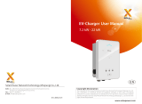
SolaX Power 7.2 kW – 22 kW EV Charger Installation guide
-
 SolaX Power G4.3 X3-Hybrid Inverter 3 Phase Installation guide
-
SolaX Power X1-Fit 3.7KW-7.5KW Installation guide
-
SolaX Power X3-Pro G2 Series Solar Inverter Installation guide
-
 SolaX Power X1-Fit-5.0E User manual
-
SolaX Power Pocket WiFi Interface V3.0 User manual
-
SolaX Power Pocket WiFi User manual


Other documents
-
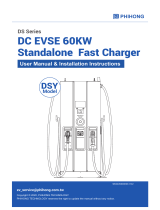
 SoleX X3-EVC-11K EV Charger 7.2 kW – 22 kW User manual
-
Sungrow SG15KTL-M User manual
-
 ZEROVA EM060DC2RG Owner's manual
-
Renogy RIV1230RCH-SPS User manual
-
Chery A Series User manual
-
 Solax X1 Matebox Advanced Installation guide
-
BMW i wallbox Installation Instructions Manual
-
 KEEWAY F-ACT EVO Instruction & Maintenance Manual
-
Huawei UPS5000-S-1200 kVA User manual
-
 KEEWAY QJ50T-21U Maintenance Manual


