Page is loading ...

1 Publication 2090-IN005A-EN-P August 2002
Installation Instructions
Ultra5000
Connector Kit
(Catalog Number 2090-U5CK-TB)
These instructions describe how to wire the I/O connectors for an
Allen-Bradley
®
Ultra5000™ Intelligent Positioning Drive. Pinouts for
the I/O connectors on the Ultra5000 drives are provided.
Contents of the Ultra5000
Connector Kit
The Ultra5000 Connector Kit includes the following items:
Wiring the CN1A and CN1B
I/O Connectors
CN1A (28-pin) and CN1B (14-pin) are plugable, double-row, spring
clamp I/O connectors with 3.5mm spacing. To wire I/O connections:
1. Strip approximately 6 mm (0.25 in.) of insulation from the end of
your I/O wires. Exercise caution not to damage wire strands as you
remove the insulation. Maximum wire gauge for these connectors
is 0.75 mm
2
(18 AWG).
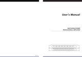
2. With the flat blade screwdriver, depress the
spring clamp next to the I/O pin you are
preparing and insert the wire, as shown.
Note: The connector is keyed by an offset bar on
the drive. Verify proper orientation of the plug
by temporarily attaching it to the I/O connector
on the drive. Always remove the plug before inserting signal wires.
3. After removing the screwdriver, gently pull on each wire to ensure
fastness. Re-insert any loose wires.
Item Description Quantity
1 CN1A - 28 pin I/O connector plug (Weidmueller 174828) 1
2 CN1B - 14 pin I/O connector plug (Weidmueller 174821) 1
3 1/16 inch flat blade screwdriver 1
ATTENTION
!
The Ultra5000 drive contains stored energy devices.
To avoid the hazard of electrical shock, verify that all
voltages on the system bus network have been
discharged before attempting to service, repair or
remove this unit. Only qualified personnel familiar
with solid state control equipment and safety
procedures in publication NFPA 70E, Standard for
Electrical Safety Requirements for Employee
Workplaces, or applicable local codes should attempt
this procedure.

Publication 2090-IN005A-EN-P August 2002 PN 0013-2059-001-01
© 2002 Rockwell Automation, Inc. All rights reserved. Printed in the U.S.A.
Allen-Bradley is a registered trademark of Rockwell Automation, Inc.
Ultra5000 is a trademark of Rockwell Automation, Inc.
Ultra5000 I/O Pinouts
The tables are arranged to match the drive’s I/O pin arrangement.
Refer to the Ultra5000 Hardware Installation Manual
(2098-IN001x-EN-P) for more information on these signals.
Related Documentation
Documents cited contain additional information concerning related
Allen-Bradley products or general information that may be helpful. To
obtain a copy, contact your local Rockwell Automation office or
distributor, or access the documents on-line at
www.theautomationbookstore.com
or
www.ab.com/manuals/gmc
.
CN1A Connector CN1B Connector
Pin Signal Pin Signal Pin Signal Pin Signal
15 INPUT9 1 INPUT1
2
8 +5VCOM 1 +5V
16 INPUT10 2 INPUT2
2
9 AIN1 2 AX+
17 INPUT11 3 INPUT3 10 AIN2 3 AX-
18 INPUT12 4 INPUT4 11 +5VCOM 4 BX+
19 INPUT13 5 INPUT5 12 AOUT1 5 BX-
20 INPUT14 6 INPUT6 13 AOUT2 6 IX+
21 INPUT15 7 INPUT7 14 SHIELD 7 IX-
22 INPUT16 8 INPUT8
23 OUTPUT5 9 OUTPUT1
24 OUTPUT6 10 OUTPUT2
25 OUTPUT7 11 OUTPUT3
26 OUTPUT8+ 12 OUTPUT4
27 OUTPUT8- 13 SHIELD
28 IOCOM
1
14 IOPWR
1
1
The Ultra5000 0.5, 1.0, and 2.0 kW, and all 460V drives (2098-IPD-005-xx, 2098-IPD-010-xx, 2098-IPD-020-xx, and
2098-IPD-HVxxx-xx models) require a user supplied I/O power source.
2
High speed inputs.
/