Page is loading ...

Installation Instructions
MP-Series Low-Inertia Servo Motor with
100 mm to 165 mm Frame Size
Catalog Numbers MPL-A310, MPL-A320, MPL-A330,
MPL-A420, MPL-A430, MPL-A4530, MPL-A4540,
MPL-A4560, MPL-A520, MPL-A540, MPL-A560, MPL-B310,
MPL-B320, MPL-B330, MPL-B420, MPL-B430, MPL-B4530,
MPL-B4540, MPL-B4560, MPL-B520, MPL-B540, MPL-B560,
MPL-B580
Topic Page
Important User Information 2
Catalog Number Explanation 3
About the MP-Series Motors 4
Before You Begin 4
Install the Motor 7
Changing the Orientation of the Connectors 7
Dimensions for Bayonet Connectors (MPL-xxxxx-xx2xxx) 12
Dimensions for Rotatable Circular DIN Connectors (MPL-xxxxx-xx7xxx) 14
Connector Data 16
Motor Load Force Ratings 18
Environmental Ratings 20
Additional Resources 22

2
Publication MP-IN001F-EN-P December 2008
Important User Information
Solid state equipment has operational characteristics differing from those of electromechanical equipment.
Safety Guidelines for the Application, Installation and Maintenance of Solid State Controls (publication
SGI-1.1
available from your local Rockwell Automation sales office or online at
http://literature.rockwellautomation.com
) describes some important differences between solid state
equipment and hard-wired electromechanical devices. Because of this difference, and also because of the
wide variety of uses for solid state equipment, all persons responsible for applying this equipment must
satisfy themselves that each intended application of this equipment is acceptable.
In no event will Rockwell Automation, Inc. be responsible or liable for indirect or consequential damages
resulting from the use or application of this equipment.
The examples and diagrams in this manual are included solely for illustrative purposes. Because of the many
variables and requirements associated with any particular installation, Rockwell Automation, Inc. cannot
assume responsibility or liability for actual use based on the examples and diagrams.
No patent liability is assumed by Rockwell Automation, Inc. with respect to use of information, circuits,
equipment, or software described in this manual.
Reproduction of the contents of this manual, in whole or in part, without written permission of Rockwell
Automation, Inc., is prohibited.
Throughout this manual, when necessary, we use notes to make you aware of safety considerations.
WARNING
Identifies information about practices or circumstances that can cause an explosion in
a hazardous environment, which may lead to personal injury or death, property
damage, or economic loss.
IMPORTANT
Identifies information that is critical for successful application and understanding of
the product.
ATTENTION
Identifies information about practices or circumstances that can lead to personal injury
or death, property damage, or economic loss. Attentions help you identify a hazard,
avoid a hazard and recognize the consequences.
SHOCK HAZARD
Labels may be on or inside the equipment (for example, drive or motor) to alert people
that dangerous voltage may be present.
BURN HAZARD
Labels may be on or inside the equipment (for example, drive or motor) to alert people
that surfaces may reach dangerous temperatures.

3
Publication MP-IN001F-EN-P December 2008
Catalog Number Explanation
FACTORY DESIGNATED OPTIONS
A = Standard
H = ATEX Protection Rating of Group II, Zone 2
MOUNTING FLANGE
A = IEC Metric
BRAKE
2=No Brake
4 = 24VDC Brake
CONNECTORS
2 = Circular Bayonet, Facing Shaft
7 = Circular DIN, Right Angle, 180° Rotatable
SHAFT KEY/SEAL
J = Shaft Key/No Shaft Seal
K = No Shaft Key/No Shaft Seal
FEEDBACK
H=
2000 Line Encoder
1
M = Multi-turn High Resolution Encoder
R=
2 Pole Resolver
1
S = Single-turn High Resolution Encoder
RATED SPEED
A = 500 rpm
B = 1000 rpm
C = 1500 rpm
D = 2000 rpm
E = 2500 rpm
F = 3000 rpm
G = 3250 rpm
H = 3500 rpm
J = 3750 rpm
K = 4000 rpm
L = 4250 rpm
M = 4500 rpm
N = 4750 rpm
P = 5000 rpm
Q = 5250 rpm
R = 5500 rpm
S = 5750 rpm
T = 6000 rpm
MAGNET STACK LENGTH (10 = 1.0 INCHES)
FRAME SIZE (IEC 72-1 FLANGE NUMBER)
1 = 55 mm Small Frame Motors (55…70 mm)
2 = 70 mm Refer to page 22
for this product manual
3 = 100 mm
4 = 115 mm
45 = 130 mm
5 = 165 mm
6 = 215 mm Large Frame Motors (215…300 mm)
8 = 265 mm Refer to page 22
for this product manual
9 = 300 mm
VOLTAGE RATING
A = 230 VAC
B = 460 VAC
SERIES TYPE
L = Low Inertia
SERIES
1 Not available on MPL-x5xxx or larger (>165mm Frame Sizes)
MP L - A 3 10 P - H K 2 2 A A
Motors in this publication

4
Publication MP-IN001F-EN-P December 2008
About the MP-Series Motors
MP-Series low-inertia motors feature single-turn or multi-turn high resolution
encoders, and are available with 24V dc brakes. These compact brushless servo
motors meet the demanding requirements of high-performance motion systems.
Before You Begin
The customer is responsible for inspecting the equipment before accepting the
shipment from the freight company. Check the item(s) you receive against your
purchase order. Notify the carrier of any shipping damage or missing items
immediately.
Store or operate your motor in a clean and dry location within the following
environmental conditions.
Before You Install the Motor
Perform the inspection steps and review the guidelines for shaft seals, couplings
and pulleys, and electrical noise prevention.
1. Remove the motor carefully from its shipping container.
2. Visually inspect the motor for any damage.
3. Examine the motor frame, front output shaft, and mounting pilot for any
defects.
4. Notify the carrier of any shipping damage immediately.
Using Shaft Seals
An additional seal is required on the motor shaft near the motor front bearing, if the
shaft is exposed to fluids or significant amounts of fine dust. This includes
lubricating oil from a gearbox. An IP66 rating for the motor requires use of a shaft
seal and environmentally sealed connectors/cables. The additional seal is not
ATTENTION
Do not attempt to open and modify the motor beyond changing the connector orientation
as described on page 7
. Only a qualified Allen-Bradley employee can service this type of
motor.
Failure to observe these safety procedures could result in personal injury or damage to
equipment.

5
Publication MP-IN001F-EN-P December 2008
recommended in applications where the motor shaft area is free of liquids or fine
dust and a lower rating will suffice.
• Refer to Environmental Ratings
for a brief description of the IP rating for
these MP-Series motors.
• Refer to Shaft Seal Kits
to find the catalog numbers of seal kits available for
your motor.
• Refer to Kinetix Motion Control Selection Guide, publication GMC-SG00
1 to
find environmentally sealed connectors and cables compatible with the
MP-Series motors.
Using Couplings and Pulleys
Mechanical connections to the motor shaft, such as couplings and pulleys, require a
torsionally rigid coupling or a reinforced timing belt. The high dynamic
performance of servo motors can cause couplings, pulleys or belts to loosen or slip
over time. A loose or slipping connection will cause system instability and may
damage the motor shaft. All connections between the system and the servo motor
shaft must be rigid to achieve acceptable response from the system. Periodically
inspect connections to verify their rigidity.
When mounting couplings or pulleys to the motor shaft, ensure that the
connections are properly aligned and that axial and radial loads are within the
specifications of the motor. Refer to Motor Load Force Ratings
for guidelines to
achieve 20,000 hours of motor bearing life.
Preventing Electrical Noise
ElectroMagnetic Interference (EMI), commonly called noise, may adversely impact
motor performance by inducing stray signals. Effective techniques to counter EMI
include filtering the AC power, shielding and separating signal carrying lines, and
practicing good grounding techniques.
Effective AC power filtering can be achieved by using isolated AC power
transformers or properly installed AC line filters.
ATTENTION
Damage may occur to the motor bearings and the feedback device if sharp impact to the
shaft is applied during installation of couplings and pulleys. Damage to the feedback
device may result by applying leverage from the motor mounting face to remove devices
mounted on the motor shaft.
Do not strike the shaft, couplings, or pulleys with tools during installation or removal. Use
a wheel puller applying pressure from the user end of the shaft to remove any friction fit or
stuck device from the motor shaft.
Failure to observe these safety procedures could result in damage to the motor and its
components.

6
Publication MP-IN001F-EN-P December 2008
Avoid the effects of EMI by following these guidelines.
• Physically separate signal lines from motor cabling and power wiring. Do
not route signal wires with motor and power wires, or over the vent
openings of servo drives.
• Ground all equipment using a single-point parallel ground system that
employs ground bus bars or large straps. If necessary, use additional
electrical noise reduction techniques to reduce EMI in noisy environments.
Refer to System Design for Control of Electrical Noise Reference Manual,
publication GMC-RM001
for additional information on reducing the effects of EMI by
improving the system level electromagnetic compatibility (EMC).
Building and Installing Cables
Knowledgeable cable routing and careful cable construction improves system
electromagnetic compatibility (EMC).
To build and install cables, perform the following steps.
1. Keep wire lengths as short as physically possible.
2. Route signal cables (encoder, serial, analog) away from motor and power
wiring.
3. Separate cables by 0.3 m (1 ft) minimum for every 9 m (30 ft) of parallel run.
4. Ground both ends of the encoder cable shield and twist the signal wire pairs
to prevent electromagnetic interference (EMI) from other equipment.
ATTENTION
High voltage can be present on the shield of a power cable, if the shield is not grounded.
Ensure there is a connection to ground for any power cable shield.
Failure to observe these safety procedures could result in personal injury or damage to
equipment.

7
Publication MP-IN001F-EN-P December 2008
Install the Motor
All motors include a mounting pilot for aligning the motor on a machine. Preferred
fasteners are stainless steel. The installation must comply with all local regulations
and use of equipment and installation practices that promote electromagnetic
compatibility and safety.
Changing the Orientation of the Connectors
MP-Series motors use two styles of connectors. The connector style is identified by
a 2 or a 7 as the connector variable in the motor catalog number. For example,
MPx-xxxxx-xx2xxx or MPx-xxxxx-xx7xxx.
• A 2 indicates a circular bayonet connector, facing the shaft.
• A 7 indicates a circular DIN, right angle, rotatable connector.
The sections below describe acceptable methods for rotating the connector
orientation for these connector styles.
ATTENTION
Unmounted motors, disconnected mechanical couplings, loose shaft keys, and
disconnected cables are dangerous if power is applied.
Disassembled equipment should be appropriately identified (tagged-out) and access to
electrical power restricted (locked-out).
Before applying power to the motor, remove the shaft key and other mechanical couplings
which could be thrown from the shaft.
Failure to observe these safety procedures could result in personal injury.
ATTENTION
Ensure that cables are installed and restrained to prevent uneven tension or flexing at the
cable connectors.
Excessive and uneven lateral force at the cable connectors may result in the connector’s
environmental seal opening and closing as the cable flexes.
Failure to observe these safety procedures could result in damage to the motor and its
components.

8
Publication MP-IN001F-EN-P December 2008
Reversible Connector Facing the Shaft (MPL-xxxxx-xx2xxx)
This connector housing can be reversed to face down when the motor is installed
in a vertical application, or rearward if connector access is restricted in a horizontal
application. Perform these steps to remount the connector housing.
1. Remove the three connector housing screws from the motor.
2. Rotate connector housing 180 degrees. If binding of the wire bundles
prevents rotation of the connector, you can gain access to the internal motor
wiring by following these steps.
a. Remove the four screws from the rear cover of the motor.
b. Carefully reposition the wires around the perimeter of the motor
feedback device located under the rear cover.
c. Be sure that the wires are not close to any rotating parts.
3. Re-install the connector housing and torque the three screws to
0.8…1.0 N•m (7…9 lb•in.) after verifying that gaskets are properly
positioned, and that no wires are pinched under the connector housing.
4. Re-install the four rear cover screws and torque them to 0.8…1.0 N•m
(7…9 lb•in) after ensuring that the rear cover O-ring is properly positioned
onto the rear cover circular pilot surface.
ATTENTION
Do not loosen or remove the motor feedback device (encoder) mounting screws while
repositioning the connector wires.
Encoder alignment is a critical adjustment that can only be performed in the factory.
Misadjustment can render the motor inoperable or degrade motor performance, and voids
the motor warranty.
Failure to observe this safety precaution could result in personal injury or damage to
equipment.
ATTENTION
Exercise caution to prevent damaging the screw holes when reinserting the self-tapping
screws holding the connector housing and rear cover.
Excessive force may strip the threads within the screw holes and prevent proper sealing of
the motor. Ensure that the specified torque values are not exceeded.
Failure to observe these safety procedures could result in damage to the motor and its
components.

9
Publication MP-IN001F-EN-P December 2008
Rotatable Circular DIN Connector (MPL-xxxxx-xx7xxx)
The circular DIN connector housing can be rotated up to 180° in either direction.
Perform these steps to turn the DIN connectors.
1. Mount and fully seat a mating cable on the connector.
2. Grasp both connectors by their housings and slowly rotate them to the
outside of the motor. If necessary, repeat this step for each connector
(feedback or power/brake).
Only apply force to the connectors; do not apply force to the cable. No tools
(for example, pliers and vise-grips) should be used to assist with the rotation
of the connector.
Install the Motor
Perform these steps to install the motor.
1. Allow sufficient clearances in the area of the motor for it to stay within its
specified operating temperature range.
Refer to Before You Begin
for the operating temperature range. Do not
enclose the motor unless forced air is blown across the motor for cooling. A
fan blowing air across the motor will improve its performance. Keep other
heat producing devices away from the motor.
To obtain the specified motor thermal rating, mount the motor on a surface
with heat dissipation equivalent to a 12 x 12 x 0.5 inch aluminum heatsink.
ATTENTION
Connectors are designed to be rotated into a fixed position during installation of the
motor, and remain in that position without further adjustment. Strictly limit the applied
forces and the number of times the connector is rotated to be sure that connectors meet
the requirements of IP66.
Failure to observe these safety procedures could result in damage to the motor and its
components.
ATTENTION
Damage may occur to the motor bearings and the feedback device if sharp impact to the
shaft is applied during installation of couplings and pulleys. Do not strike the shaft,
couplings, or pulleys with tools during installation or removal.
Failure to observe these safety procedures could result in damage to the motor and its
components.

10
Publication MP-IN001F-EN-P December 2008
2. Refer to Motor Load Force Ratings to determine the radial and axial shaft
load limitations of your motor.
3. Place the motor with the connector housing pointing downward.
4. Mount and align the motor.
Electronic zero, Index pulse or Stegmann ABS = 0, occurs when the shaft
key or dimple is aligned with the connectors.
Refer to Mounting Dimensions
for a visual reference of this alignment.
5. Attach all power, feedback, and brake cables after the motor is mounted,
and use a drip loop in the cable to keep liquids away from the connectors.
Use this procedure to attach the cable connectors.
ATTENTION
Outer surfaces of motor can reach high temperatures, 125 °C (275 °F) during motor
operation.
Take precautions to prevent accidental contact with hot surfaces. Consider motor surface
temperature when selecting motor mating connections and cables.
Failure to observe these safety procedures could result in personal injury or damage to
equipment.
ATTENTION
Keyed connectors must be properly aligned and hand-tightened the recommended number
of turns.
Improper connector alignment is indicated by the need for excessive force, such as the use
of tools, to fully seat connectors.
Failure to observe these safety procedures could result in damage to the motor and cable,
and their components.
ATTENTION
When installing threaded DIN style cable connectors, O-rings are required on the motor
connectors. The O-rings provide ingress protection.
Cables requiring O-rings include power cable 2090-XXNPMF-xxSx or
2090-CPxM4DF-xxAFxx, and feedback cable 2090-XXNFMF-Sxx or
2090-CFBM4DF-CDAFxx.
Flex cables with a threaded DIN style connector have an M4 designation.

11
Publication MP-IN001F-EN-P December 2008
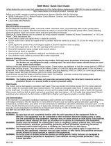
a. Carefully align each cable connector with the respective motor connector
as shown in the following diagram. Do not apply excessive force when
mating the cable and motor connectors. If the connectors do not go
together with light hand force, realign and try again.
b. Hand tighten the knurled collar 5 to 6 turns to fully seat each connector.
If your motor has an ATEX rating for hazardous environments, complete the
following step. The catalog number on ATEX motor nameplates ends with
H, for example MPL-xxxxx-xxxxH.
6. Verify the continuity and functionality of the thermal switch signals, TS+ and
TS-, transmitted through the feedback cable that connects the motor to its
controlling drive.
WARNING
It is mandatory that the motion system monitor the thermal switch signals from a motor
requiring an ATEX rating.
The intrinsic safety protection concepts in the ATEX Direction 94/9/EC must be enabled
by connecting the thermal switch signals from the motor to the motion control system.
Failure to observe these safety procedures may lead to personal injury or death, damage
to the equipment, or economic loss.
Flat surface with
logo on top
Feedback Plug Options
Tab on
side
Power Plug Options
Note: Top of
connector is
relative to motor
orientation.
Flat surface
with logo on
top
Tab on
top
Connector plugs have either a tab or a flat surface with a logo to indicate the alignment point.

12
Publication MP-IN001F-EN-P December 2008
Dimensions for Bayonet Connectors (MPL-xxxxx-xx2xxx)
L
P
GE
LA
LB
T
L-LB
LE
AD
HD
S
M
N
F
3.3 (0.13)
88.9 (3.5)
67.8 (2.67)
MPL-x3xx = 5 x 5 x 25
MPL-x4xx = 6 x 6 x 25
MPL-x45xx = 8 x 7 x 32
MPL-x520, x540, x560 = 8 x 7 x 40
MPL-x580 = 10 x 8 x 59
(Pilot Diameter)
Shaft End Hole
Thread and Depth
Shaft Key
Feedback, Power, and Brake
Connectors (left to right)
Feedback and Power
Connectors (left to right)
MPL-xxxxx-xx2xxx
Connector
Note: Electronic zero (Index pulse or Stegmann ABS = 0) occurs when the shaft key or dimple (not shown) is aligned with the connectors (as shown).
Add for High
Resolution End Cap
(Diameter of Holes)
(Diameter of Bolt Circle)

13
Publication MP-IN001F-EN-P December 2008
Motor
Series
MPL-A
or MPL-B
AD
mm
(in.)
D *
mm
(in.)
HD
mm
(in.)
L
1, 2
mm
(in.)
L-LB
3
mm
(in.)
LA
mm
(in.)
LB
1, 2
mm
(in.)
LD
1
mm
(in.)
M
mm
(in.)
N *
mm
(in.)
P
mm
(in.)
S
4
mm
(in.)
T
mm
(in.)
F
5
mm
(in.)
GE
6
mm
(in.)
End of Shaft
Thread and
Depth of Hole
310
80.9
(3.19)
16.0
(0.629)
125.7
(4.95)
164.7
(6.49)
40.0
(1.58)
9.9
(0.39)
124.7
(4.91)
70.7
(2.78)
100.0
(3.937)
80.0
(3.15)
89.4
(3.52)
7.0
(0.283)
2.87
(0.113)
5.0
(0.20)
3.0
(0.12)
M5 x 0.8-6H x
12.5 (0.49)
320
190.1
(7.49)
150.1
(5.91)
96.1
(3.78)
330
215.5
(8.49)
175.5
(6.91)
121.5
(4.78)
420
83.9
(3.3)
19.0
(0.748)
132.8
(5.23)
186.5
(7.35)
40.0
(1.575)
10.2
(0.40)
146.5
(5.77)
92.5
(3.64)
115.0
(4.528)
95.0
(3.74)
98.3
(3.87)
10.0
(0.401)
2.87
(0.113)
6.0
(0.24)
3.5
(0.138)
M6 x 1.0-6H x
16 (0.63)
430
211.9
(8.345)
171.9
(6.77)
117.9
(4.64)
4530
91.5
(3.6)
24.0
(0.945)
148.3
(5.84)
225.2
(8.87)
50.0
(1.97)
12.2
(0.48)
175.2
(6.90)
121.2
(4.77)
130.0
(5.118)
110.0
(4.331)
113.7
(4.48)
10.0
(0.401)
3.38
(0.133)
8.0
(0.31)
4.0
(0.158)
M8 x 1.25 -6H x
19 (0.75)
4540
250.6
(9.87)
200.6
(7.90)
146.6
(5.77)
4560
304.7
(11.99)
254.7
(10.03)
197.4
(7.77)
520
106.2
(4.18)
28.0
(1.1)
178.1
(7.01)
233.7
(9.20)
60.0
(2.38)
13.97
(0.55)
173.7
(6.84)
115.8
(4.56)
165.0
(6.496)
130.0
(5.118)
143.5
(5.65)
12.0
(0.481)
3.38
(0.133)
8.0
(0.31)
4.0
(0.158)
M10 x 1.5-6H x
22 (0.87)
540
284.5
(11.20)
224.5
(8.84)
166.9
(6.57)
560
335.3
(13.20)
275.3
(10.84)
217.7
(8.56)
580
7
32.0
(1.26)
406.1
(15.99)
80.0
(3.15)
326.1
(12.84)
268.5
(10.57)
10.0
(0.39)
5.0
(0.197)
M12 x 1.75-6H
x
28 (1.10)
1 Motors with brake, add this value to the dimension:
MPL-x310 through -x330: add 34.5 mm (1.36 in.) to L, LB, and LD.
MPL-x420 through -x4560: add 48.5 mm (1.91 in.) to L, LB, and LD.
MPL-x520 through -x580 add 51.6 mm (2.03 in.) to L and LB, and 45.6 mm (1.79 in.) to LD.
2 Motors with high-resolution feedback, add 3.3 mm (0.13 in.) to L and LB.
3 Tolerance is ±0.7 (±0.028).
4 x3xx and x4xx tolerance is +0.36 (±0.0007), x5xx is +0.43 (±0.008).
5 Tolerance is -0.03 (-0.001).
6 Tolerance is +0.1 (+0.004).
7 This motor is only available with 460V windings (MPL-B580)
Refer to Kinetix Motion Control Selection Guide, publicatio
n GMC-SG001 for tolerances on these measurements.

14
Publication MP-IN001F-EN-P December 2008
Dimensions for Rotatable Circular DIN Connectors (MPL-xxxxx-xx7xxx
)
S
M
AD
HD
L
P
GE
LA
LB
T
L-LB
D
LE
N
LD
AD + 22.99 (0.90)
HD + 22.95 (9.01)
LE - 31 (1.22)
F
MPL-x3xx = 5 x 5 x 25
MPL-x4xx = 6 x 6 x 25
MPL-x45xx = 8 x 7 x 32
MPL-x5xx = 8 x 7 x 40
MPL-x580 = 10 x 8 x 59
MPL-x3xx = 66.1 (2.60)
MPL-x4xx = 67.7 (2.66)
MPL-x45xx = 67.7 (2.66)
MPL-B520-xx7xxx, MPL-B540-xx7xxx,
and MPL-B560-xx7xxx = 68.2 (2.68)
LD + 2.0 (0.07)
MPL-A520-xx7xxx, MPL-A540-xx7xxx,
MPL-A560-xx7xxx , and
MPL-B580x-xx7xxx = 71.2 (2.80)
(Pilot Diameter)
Shaft End Hole
Thread and Depth
Shaft Key
MPL-x5xx
End Cap
M23 Power/Brake Connector
is standard on the
Note: Electronic zero (Index pulse or Stegmann ABS = 0) occurs when the shaft key or dimple (not shown) is aligned with the connectors (as shown).
M40 Power/Brake Connector
is standard on the
Dimensions for M40 Power/Brake Connector on the
MPL-A5xxx-xx7xxx and the MPL-B580x-xx7xxx motors.
M23 Feedback
Connector shown
for comparison
(Diameter of Holes)
(Diameter of Bolt Circle)
M23 Feedback Connector
is standard on all MPL motors

15
Publication MP-IN001F-EN-P December 2008
Motor
Series
MPL-A
or MPL-B
AD
mm
(in.)
D *
mm
(in.)
HD
mm
(in.)
L
1
mm
(in.)
L-LB
2
mm
(in.)
LA
mm
(in.)
LB
1
mm
(in.)
LD
1
mm
(in.)
LE
1
mm
(in.)
M
mm
(in.)
N *
mm
(in.)
P
mm
(in.)
S
3
mm
(in.)
T
mm
(in.)
F
4
mm
(in.)
GE
5
mm
(in.)
End of Shaft
Thread and
Depth of
Hole
310
87.2
(3.44)
16.0
(0.629)
132.0
(5.20)
168.0
(6.62)
40.0
(1.575)
9.90
(0.39)
128.0
(5.04)
62.0
(2.45)
102.0
(4.03)
100.0
(3.937)
80.0
(3.15)
89.4
(3.52)
7.0
(0.283)
2.74
(0.108)
5.0
(0.20)
3.0
(0.12)
M5 x 0.8-6H
x
12.5 (0.49)
320
193.0
(7.62)
153.0
(6.04)
88.0
(3.45)
128.0
(5.03)
330
219.0
(8.62)
179.0
(7.04)
113.0
(4.45)
153.0
(6.03)
420
90.9
(3.58)
19.0
(0.749)
140.1
(5.52)
190.0
(7.48)
40.0
(1.575)
10.16
(0.40)
150.0
(5.90)
84.0
(3.31)
124.0
(4.89)
115.0
(4.528)
95.0
(3.74)
98.3
(3.87)
10.0
(0.401)
6.0
(0.234)
3.5
(0.138)
M6 x 1.0-6H
x
16 (0.63)
430
215.0
(8.48)
175.0
(6.90)
110.0
(4.31)
150.0
(5.89)
4530
98.6
(3.88)
24.0
(0.945)
155.4
(6.12)
229.0
(9.0)
50.0
(1.97)
12.19
(0.48)
179.0
(7.03)
113.0
(4.44)
153.0
(6.02)
130.0
(5.118)
110.0
(4.331)
113.7
(4.48)
10.0
(0.401)
2.74
(0.108)
8.0
(0.31)
4.0
(0.158)
M8 x 1.25
-6H x
19 (0.75)
4540
254.0
(10.0)
204.0
(8.03)
138.0
(5.44)
178.0
(7.02)
4560
305
(12.0)
255.0
(10.03)
189.0
(7.44)
229.0
(9.02)
520
113.4
(4.47)
28.0
(1.102)
185.2
(7.29)
237.0
(9.33)
60.0
(2.38)
14.0
(0.55)
176.0
(6.92)
109.0
(4.30)
149.0
(5.88)
165.0
(6.496)
130.0
(5.118)
143.5
(5.65)
12.0
(0.481)
3.12
(0.123)
8.0
(0.31)
4.0
(0.158)
M10 x 1.5-6H
x
22 (0.87)
540
287.0
(11.30)
227.0
(8.92)
162.0
(6.30)
200.0
(7.88)
560
337.0
(13.27)
277.0
(10.90)
211.0
(8.30)
251.0
(9.88)
580
6
136.4
(5.37)
32.0
(1.259)
208.1
(8.19)
408.0
(16.06)
80.0
(3.15)
328.0
(12.91)
232.0
(9.13)
304.0
(11.95)
10.0
(0.39)
5.0
(0.197)
M12 x
1.75-6H x
28 (1.10)
1 Motors with brake, add this value to the dimension:
MPL-x310 through -x330: add 35.0 mm (1.37 in.) to L, LB, and LD.
MPL-x420 through -x4560: add 48.0 mm (1.89 in.) to L, LB, and LD.
MPL-x520 through -x560 add 51.0 mm (2.03 in.) to L and LB, and LD.
MPL-B580 add 45.6 mm (1.79 in.) to L and LB, and 52.0 mm (2.05 in.) to LD and LE.
2 Tolerance for this dimension is ±0.7 (±0.028).
3 x3xx and x4xx tolerance is +0.36 (±0.0007), x5xx is +0.43 (±0.008)
4 Tolerance for this dimension is -0.03 (-0.001).
5 Tolerance for this dimension is +0.1 (+0.004).
6MPL-B580x is available only with 460V windings.
* Refer to Kinetix Motion Control Selection Guide, publicatio
n GMC-SG001 for tolerances on these measurements.

16
Publication MP-IN001F-EN-P December 2008
Connector Data
The table below list the signal descriptions for the feedback, power, and brake
connector pins on the MPL-xxxxx-xx2xxx connector style.
Feedback Connector Power Connector
High Resolution Encoder for: Pin Signal
2000 Line 2 Pole
MPL-A3xx through
-A45xx
MPL-A5xx, and all
MPL-B (460V)
APhase U
Pin Encoder Resolver
BPhase V
A AM+ S2 SIN+ SIN+ C Phase W
B AM- S4 SIN- SIN- D Ground
C BM+ S1 COS+ COS+
D BM- S3 COS- COS-
E IM+ Reserved DATA+ DATA+
F I-M DATA- DATA-
G Ground R1 Reserved Reserved
H ABS R2
J Reserved Reserved
K EPWR_5 V +5 VDC
L ECOM Common
M Reserved Reserved Brake Connector
N +9 VDC Pin Signal
P Common A
MBRK+
R TS+ TS+ TS+ TS+ B Reserved
S TS- TS- TS- TS- C
MBRK-
T S1 Reserved Reserved Reserved D Reserved
US2
VS3
A
B
C
D
ITT Cannon
TNM 16-4, 192993-0106
A
B
C
D
ITT Cannon
TNM 10-4, 192993-0116
A
B
C
D
E
F
G
H
J
K
L
M
N
P
R
S
T
U
V
ITT Cannon
TNM 16-19, 192993-0110

17
Publication MP-IN001F-EN-P December 2008
The table below list the signal descriptions for the feedback, power, and brake
connector pins on the MPL-xxxxx-xx7xxx connector style.
Feedback Power and Brake
Pin High Resolution
Encoder
High Resolution
Encoder
Incremental Encoder Pin MPL-Axxx and
MPL-Bxxx
MPL-Axxx (230V) MPL-Bxxx (460V) MPL-A/Bxxxx-Hxxxx
1 SIN+ SIN+ AM+ A Phase U
(2)
(2)
Power pins A, B, C, and D may be labelled as U, V, W, and GND respectively. Brake pins F and G brake may be labelled as +
and - respectively. Reserved pins E and H may be numbered 1 or 2.
2 SIN- SIN- AM- B Phase V
(2)
3 COS+ COS+ BM+ C Phase W
(2)
4 COS- COS- BM- D Ground
(2)
5 DATA+ DATA+ IM+ E Reserved
(2)
6 DATA- DATA- IM- F MBRK+
(2)
7 Reserved Reserved Reserved G MBRK-
(2)
8HReserved
(2)
9 EPWR_5V EPWR_5V L
(1)
(1)
M23 (BEDC…) connector has nine pins, and the M40 (CEDE…) connector has eight pins.
10 ECOM ECOM M23 Connector
M40 Connector
11 Reserved EPWR_9V Reserved
12 ECOM
13 TS+ TS+ TS+
14 TS- TS- TS-
15 Reserved Reserved S1
16 S2
17 S3
B C
A
G
L
F
E
H
D
Intercontec P/N
BEDC090NN00000005000
V
UW
12
+
-
Intercontec P/N
CEDE271NN00000051000
1
2
3
4
5
6
7
8
9
10
11
12
13
14
17
15
16
Intercontec P/N
AEDC113NN00000012000

18
Publication MP-IN001F-EN-P December 2008
Motor Load Force Ratings
Motors are capable of operating with a sustained shaft load. The radial and axial
load force location is shown in the figure, and maximum values are in the tables.
Load Forces on Shaft
The following tables represent 20,000 hour L10 bearing fatigue life at various loads
and speeds. This 20,000 hour life does not account for possible application-specific
life reduction that may occur due to bearing grease contamination from external
sources.
Radial Load Force Ratings
Motor
500 rpm 1000 rpm 2000 rpm 3000 rpm 3500 rpm 4000 rpm 5000 rpm
kg (lb) kg (lb) kg (lb) kg (lb) kg (lb) kg (lb) kg (lb)
MPL-A/B310 78 (171) 62 (136) 49 (108) — — 40 (89) — — 36 (79)
MPL-A/B320 87 (192) 69 (152) 55 (121) — — 45 (100) — — 40 (89)
MPL-A/B330 — — 74 (163) 59 (129) — — 49 (107) — — 43 (95)
MPL-A/B420 — — 78 (172) 62 (136) — — 51 (113) — — 45 (100)
MPL-A/B430 106 (234) 84 (186) 67 (148) — — 55 (122) — — 49 (109)
MPL-A/B4520 — — 97 (213) 77 (169) 67 (147) 64 (140) 61 (134) 56 (124)
MPL-A/B4530 133 (292) 105 (232) 84 (184) 73 (161) — — 66 (146) — —
MPL-A/B4540 140 (309) 111 (245) 89 (195) 77 (170) ——————
MPL-A/B4560 151 (332) 119 (263) 95 (209) 83 (183) ——————
MPL-A/B520 — — 127 (280) 100 (222) 88 (194) — — 80 (176) — —
MPL-A/B540 — — 143 (316) 114 (251) 99 (219) — — 90 (199) — —
MPL-A/B560 — — 153 (338) 121 (268) 106 (234) ——————
MPL-B580 — — 153 (338) 121 (268) 106 (234) ——————
Axial load force
Radial load force applied at center of shaft extension

19
Publication MP-IN001F-EN-P December 2008
Axial Load Force Ratings (Maximum Radial Load)
Axial Load Force Ratings (Zero Radial Load)
Motor
500 rpm 1000 rpm 2000 rpm 3000 rpm 3500 rpm 4000 rpm 5000 rpm
kg (lb) kg (lb) kg (lb) kg (lb) kg (lb) kg (lb) kg (lb)
MPL-A/B310 30 (66) 23 (50) 16 (36) — — 13 (29) — — 11 (24)
MPL-A/B320 34 (74) 25 (56) 19 (41) — — 15 (32) — — 13 (28)
MPL-A/B330 — — 27 (59) 20 (44) — — 16 (35) — — 13 (29)
MPL-A/B420 — — 36 (80) 27 (59) — — 21 (47) — — 18 (39)
MPL-A/B430 52 (115) 39 (86) 29 (63) — — 22 (49) — — 19 (42)
MPL-A/B4520 — — 31 (68) 23 (50) 19 (42) 18 (39) 17 (37) 15 (33)
MPL-A/B4530 45 (100) 34 (74) 25 (55) 21 (46) — — 19 (41) — —
MPL-A/B4540 49 (107) 36 (80) 27(59) 22(49) ——————
MPL-A/B4560 53 (117)40(88)30(65)24(53) ——————
MPL-A/B520 — — 42 (94) 30 (68) 26 (58) — — 22 (50) — —
MPL-A/B540 — — 48 (107) 35 (79) 30 (66) — — 26 (58) — —
MPL-A/B560——52(115)43(95)32(71)——————
MPL-B580 ——52(115)43(95)32(71)——————
Motor
500 rpm 1000 rpm 2000 rpm 3000 rpm 3500 rpm 4000 rpm 5000 rpm
kg (lb) kg (lb) kg (lb) kg (lb) kg (lb) kg (lb) kg (lb)
MPL-A/B310 49 (109) 36 (80) 27 (59) — — 21 (47) — — 18 (40)
MPL-A/B320 49 (109) 36 (80) 27 (59) — — 21 (47) — — 18 (40)
MPL-A/B330 — — 36 (80) 27 (59) — — 21 (47) — — 18 (40)
MPL-A/B420 — — 51 (112) 38 (83) — — 30 (65) — — 25 (55)
MPL-A/B430 69 (152) 51 (112) 38 (83) — — 30 (65) — — 25 (55)
MPL-A/B4520 — — 51 (112) 38 (83) 31 (69) 30 (65) 28 (61) 25 (55)
MPL-A/B4530 69 (152) 51 (112) 38 (83) 31 (69) — — 28 (61) — —
MPL-A/B4540 69(152)51(112)38(83)31(69)——————
MPL-A/B4560 69(152)51(112)38(83)31(69)——————
MPL-A/B520 — — 67 (149) 49 (109) 41 (92) — — 36 (81) — —
MPL-A/B540 — — 67 (149) 49 (109) 41 (92) — — 36 (81) — —
MPL-A/B560 — — 67 (149) 49 (109) 41 (92) — —————
MPL-B580 — — 67 (149) 49 (109) 41 (92) — —————

20
Publication MP-IN001F-EN-P December 2008
Environmental Ratings
Motor feedback, auxiliary feedback, and I/O connector kits are not provided. Refer
to the Kinetix Motion Control Selection Guide, publication GMC-SG001, for
connector kit catalog numbers.
Cables and Connector Kits
Factory manufactured feedback and power cables are available in standard cable
lengths. They can provide environmental sealing and shield termination. Contact
your nearest Allen-Bradley sales office or refer to your drive’s installation manual
for a complete listing of available cables.
If you choose to build your own cables, connector kits available for MP-Series Small
Frame motors are described in the Kinetix Motion Control Selection Guide,
publication GMC-SG001.
Attribute Value
Temperature, operating 0…40 °C (32…104 °F)
Temperature, storage -30…70 °C (-22…158° F)
Relative humidity, storage 5…95% non-condensing
Atmosphere, storage non-corrosive
IP Rating
(1)
of motor with optional shaft seal
(2)
installed
(1)
International Protection Code (IP 66) is roughly equivalent to a NEMA 35 (dust tight, drip tight).
(2)
An optional shaft seal kit is required to provide the IP66 rating (excludes lower rating for cable connectors).
See Additional Resources on page 22
for shaft seal installation instructions.
IP 66 (dust tight, heavy jet spray)
Motor without a shaft seal, and mounted in this direction.
shaft down
shaft horizontal
shaft up
IP53
IP51
IP50
ATEX rating
(3)
(3)
Operational environment according to ATEX directive 94/9/EC. See motor label for specific level of protection markings.
Group II, Zone 2
(non-mining, normal operating
conditions)
/