Page is loading ...

Installation Instructions
MP-Series Low Inertia Servo Motor
with 215 mm or Larger Frame Size
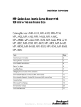
Catalog Numbers MPL-B640, MPL-B660, MPL-B680,
MPL-B860, MPL-B880, MPL-B960, MPL-B980
Topic Page
Important User Information 2
Catalog Number Explanation 3
Before You Begin 4
Install the Motor 8
Verify Connector O-ring and Backshell Seal 8
Change Connector Orientation 9
Mount the Motor 13
Connector Data 16
Product Dimensions 17
Motor Load Force Ratings 20
Accessory Kits 22
Specifications 24
Additional Resources 25

2 MP-Series Low Inertia Servo Motor Installation Instructions
Publication MP-IN002C-EN-P - April 2009
Important User Information
Solid state equipment has operational characteristics differing from those of electromechanical equipment.
Safety Guidelines for the Application, Installation and Maintenance of Solid State Controls, publication
SGI-1.1
, is available from your local Rockwell Automation sales office or online at
http://literature.rockwellautomation.com
) describes some important differences between solid state
equipment and hard-wired electromechanical devices. Because of this difference, and also because of the
wide variety of uses for solid state equipment, all persons responsible for applying this equipment must
satisfy themselves that each intended application of this equipment is acceptable.
In no event will Rockwell Automation, Inc. be responsible or liable for indirect or consequential damages
resulting from the use or application of this equipment.
The examples and diagrams in this manual are included solely for illustrative purposes. Because of the many
variables and requirements associated with any particular installation, Rockwell Automation, Inc. cannot
assume responsibility or liability for actual use based on the examples and diagrams.
No patent liability is assumed by Rockwell Automation, Inc. with respect to use of information, circuits,
equipment, or software described in this manual.
Reproduction of the contents of this manual, in whole or in part, without written permission of Rockwell
Automation, Inc., is prohibited.
Throughout this manual, when necessary, we use notes to make you aware of safety considerations.
WARNING
Identifies information about practices or circumstances that can cause an explosion in
a hazardous environment, which may lead to personal injury or death, property
damage, or economic loss.
IMPORTANT
Identifies information that is critical for successful application and understanding of
the product.
ATTENTION
Identifies information about practices or circumstances that can lead to personal injury
or death, property damage, or economic loss. Attentions help you identify a hazard,
avoid a hazard and recognize the consequences.
SHOCK HAZARD
Labels may be on or inside the equipment, for example, a drive or motor, to alert
people that dangerous voltage may be present.
BURN HAZARD
Labels may be on or inside the equipment, for example, a drive or motor, to alert
people that surfaces may reach dangerous temperatures.

MP-Series Low Inertia Servo Motor Installation Instructions 3
Publication MP-IN002C-EN-P - April 2009
Catalog Number Explanation
FACTORY DESIGNATED OPTIONS
A = Standard
H = ATEX Protection Rating of Group II, Zone 2
MOUNTING FLANGE
A = IEC Metric
BRAKE
2 = No Brake
4 = 24V DC Brake
CONNECTORS
2 = Bayonet, Right Angle, 180° Rotatable
7 = Circular DIN, Right Angle, 180° Rotatable
ENCLOSURE/SHAFT KEY/SHAFT SEAL
J = Shaft Key
K = No Shaft Key
FEEDBACK
M = Multi-turn High Resolution Encoder
S = Single-turn High Resolution Encoder
RATED SPEED
A = 500 rpm
B = 1000 rpm
C = 1500 rpm
D = 2000 rpm
E = 2500 rpm
F = 3000 rpm
G = 3250 rpm
H = 3500 rpm
J = 3750 rpm
K = 4000 rpm
MAGNET STACK LENGTH (80 = 8.0 in.)
FRAME SIZE (IEC 72-1 flange number)
6 = 215 mm
8 = 265 mm
9 = 300 mm
VOLTAGE RATING
B = 460 V AC
SERIES TYPE
L=Low-inertia
SERIES
MP = MP-Series
MP L -B 6 80 F -MJ 7 2 A A

4 MP-Series Low Inertia Servo Motor Installation Instructions
Publication MP-IN002C-EN-P - April 2009
About the MP-Series Low Inertia Motors
MP-Series low-inertia motors feature single-turn or multi-turn high resolution
encoders, and are available with 24V DC brakes. These compact brushless servo
motors combine the characteristics of the MP-Series low-inertia motors with unique
features designed for food and beverage applications.
Before You Begin
Remove all packing material, wedges, and braces from within and around the item.
After unpacking, verify the nameplate catalog number against the purchase order.
1. Remove the motor carefully from its shipping container.
2. Visually inspect the motor frame, shaft, mounting pilot, and encoder for
damage.
3. Notify the carrier of any shipping damage immediately.
Prolonging Motor Life
Thoughtful design and proper maintenance can increase the life of a servo motor.
Follow these guidelines to maximize the life of a servo motor within a food
processing environment.
• Always provide a drip loop in each cable to carry liquids away from the
connection to the motor.
• If design requirements permit, provide shields that protect the motor
housing, shaft, seals and their junctions from contamination by foreign
matter or fluids.
• Replace the shaft seal at or before its expected lifetime of 12-months.
Refer to Shaft Seals
for more information on shaft seals.
• Inspect the motor and seals for damage or wear on a regular basis. If
damage or excessive wear is observed, replace the item.
ATTENTION
Do not attempt to open or modify this motor beyond changing the connector orientation as
described in Change Connector Orientation
.
Only an authorized Allen-Bradley repair center shall service this item. Refer to Rockwell
Automation Support for assistance to locate the nearest repair center.
Failure to observe safety precautions could result in personal injury or damage to
equipment.

MP-Series Low Inertia Servo Motor Installation Instructions 5
Publication MP-IN002C-EN-P - April 2009
• The brake option on this servo motor is a spring-set holding brake that
releases when voltage is applied to the brake coil. A separate power source
is required to disengage the brake. This power source can be applied by a
servo motor controller or manual operator control.
If system main power fails, holding brakes can withstand occasional use as
stopping brakes. However, this creates rotational mechanical backlash that is
potentially damaging to the system, increases brake wear, and reduces brake
life.
Using Shaft Seals
A seal may be installed on the motor shaft to protect the front bearing from fluids
or fine dust that could contaminate the motor bearing and reduce its lifetime. An
IP66 rating for the motor requires the use of shaft seals, connectors, and cables that
provide an environmental seal equal to or exceeding the rating.
• Refer to Specifications
for a brief description of the IP ratings.
• Refer to Shaft Seals
to find the catalog numbers of seal kits for your motor.
• Refer to the Kinetix Motion Control Selection Guide, publication
GMC-SG001
, to find environmentally sealed connectors and cables that are
compatible with MP-Series motors.
IMPORTANT
Holding brakes are not designed to stop rotation of the motor shaft, nor are they
intended to be used as a safety device. They are designed to hold a motor shaft
at 0 rpm for up to the rated brake holding torque.
The recommended method of preventing motor shaft rotation is a four step
process: first - command the servo drive to 0 rpm, second - verify the motor is at
0 rpm, third - engage the brake; and fourth - disable the drive.
Disabling the drive removes the potential for brake wear caused by a badly tuned
servo system oscillating the shaft.

6 MP-Series Low Inertia Servo Motor Installation Instructions
Publication MP-IN002C-EN-P - April 2009
Using Couplings and Pulleys
Mechanical connections to the motor shaft, such as couplings and pulleys, require a
torsionally rigid coupling or a reinforced timing belt. The high dynamic
performance of servo motors can cause couplings, pulleys, or belts to loosen or slip
over time. A loose or slipping connection causes system instability and can damage
the motor shaft. All connections between the system and the servo motor shaft must
be rigid to achieve an acceptable response from the system. Periodically inspect
connections to verify their rigidity.
When mounting couplings or pulleys to the motor shaft, make sure that the
connections are properly aligned and that axial and radial loads are within the
specifications of the motor. Refer to Shaft Seals
for guidelines to achieve 20,000
hours of motor bearing life.
A shaft key provides a rigid mechanical connection with the potential for
self-alignment when the key is properly installed. These sections provide additional
information:
• Refer to Product Dimensions
for information about the key and shaft
keyway.
• Refer to Shaft Key
for recommendations on how to remove and install a
shaft key.
ATTENTION
Damage may occur to the motor bearings and the feedback device if sharp impact is applied
to the shaft during installation of couplings and pulleys. Damage to the feedback device
may result from applying leverage to the motor mounting face when removing devices
mounted on the motor shaft.
Do not strike the shaft, couplings, or pulleys with tools during installation or removal. Use a
wheel puller to apply pressure from the user end of the shaft to remove any device from the
motor shaft.
Failure to observe safety precautions could result in damage to the motor and its
components.

MP-Series Low Inertia Servo Motor Installation Instructions 7
Publication MP-IN002C-EN-P - April 2009
Preventing Electrical Noise
ElectroMagnetic Interference (EMI), commonly called electrical noise, can reduce
motor performance. Effective techniques to counter EMI include filtering the AC
power, use of shielded cables, separating signal cables from power wiring, and
practicing good grounding techniques.
Follow these guidelines to avoid the effects of EMI:
• Isolate the power transformers or install line filters on all AC input power
lines.
• Physically separate signal cables from motor cabling and power wiring. Do
not route signal cables with motor and power wires, or over the vent
openings of servo drives.
• Ground all equipment using a single-point parallel ground system that
employs ground bus bars or large straps. If necessary, use additional
electrical noise reduction techniques to reduce EMI in noisy environments.
Refer to System Design for Control of Electrical Noise Reference Manual,
publication GMC-RM001
, for additional information on reducing the effects of EMI.

8 MP-Series Low Inertia Servo Motor Installation Instructions
Publication MP-IN002C-EN-P - April 2009
Install the Motor
All motors include a mounting pilot for aligning the motor on the machine.
Preferred fasteners are hardened steel. The installation must comply with all local
regulations and use equipment and installation practices that promote safety and
electromagnetic compatibility.
Verify Connector O-ring and Backshell Seal
An O-ring on the feedback connector, and a backshell seal on the feedback and
power/brake connectors are necessary to achieve the maximum environmental
rating. Verify the seal and O-rings are installed as described.
ATTENTION
Unmounted motors, disconnected mechanical couplings, loose shaft keys, and
disconnected cables are dangerous if power is applied.
Disassembled equipment should be appropriately identified (tagged-out) and access to
electrical power restricted (locked-out).
Before applying power to the motor, remove the shaft key and other mechanical couplings
which could be thrown from the shaft.
Failure to observe safety precautions could result in personal injury.
ATTENTION
Make sure that cables are installed and restrained to prevent uneven tension or flexing at
the cable connections.
Excessive and uneven lateral force on the cable can result in the environmental seal
opening and closing as the cable flexes.
Failure to observe safety precautions could result in damage to the motor and its
components.
Location Verify
• An O-ring is mounted on the external surface of
the feedback connector and the power/brake
connector.
• The O-ring is undamaged, not twisted, and rests
in the groove near the rear of the connector.
• A backshell seal covers the joint inside the
feedback and power/brake housings. It seals the
joint between the backshell and the housing of
the connector.
• The backshell seal is undamaged, and it is fully
seated against the face of the backshell.
O-ring
Groove Reserved For
Quick-lock Plug
Backshell Seal Inside
Feedback and
Power/Brake
Connector Housing

MP-Series Low Inertia Servo Motor Installation Instructions 9
Publication MP-IN002C-EN-P - April 2009
Change Connector Orientation
You may rotate the connector housings up to 180 degrees.
• The M23 feedback connector and the M40 power/brake connector are fully
rotatable as installed.
• The M58 power/brake connector, on MPL-B8xx and MPL-B9xx motors with
higher current requirements, must be physically removed and repositioned
in 90° increments.
This lets you to rotate the connector into a position that best protects the
connection from possible environmental contaminates while providing cable
access.
Rotating the M23 Feedback or M40 Power/Brake Circular DIN Connector
Follow these steps to rotate an M23 feedback or a M40 power/brake connector.
1. Mount and fully seat a mating cable on either the feedback or power/brake
connector.
2. Grasp the mated connector and cable plug and slowly rotate them to the
outside of the motor.
ATTENTION
Connectors are designed to be rotated into a fixed position during motor installation, and
remain in that position without further adjustment. Strictly limit the applied forces and the
number of times the connector is rotated to make sure that connectors meet the
appropriate International Protection (IP) rating as outlined in Specifications
.
Failure to observe safety precautions could result in damage to the motor and its
components.
IMPORTANT
Do not use tools, such as pliers or vise-grips, to assist you in rotating an M23 feedback or
M40 power/brake connector.
Only apply force to the connector. Do not apply force to or pull on the cable.
ATTENTION
Apply force only to the motor connector and cable plug. Do not apply force to
the cable extending from the cable plug. No tools, for example pliers or
vise-grips, should be used to assist with the rotation of the connector.
Failure to observe safety precautions could result in damage to the motor and
its components.

10 MP-Series Low Inertia Servo Motor Installation Instructions
Publication MP-IN002C-EN-P - April 2009
Rotating the M58 Power/Brake Circular DIN Connector
Follow these steps to rotate a M58 power/brake DIN connector.
1. Remove the four 10-32 x 5/8 locking screws from the connector housing.
2. Rotate the connector housing 90 or 180 degrees.
If binding of the wire bundles prevents rotation of the connector, you can
gain access to the internal motor wiring as described in the following steps.
a. Remove the four screws from the rear cover of the motor.
b. Reposition the wires with care around the perimeter of the motor
feedback device under the rear cover.
c. Verify that wires are not close to any rotating parts, and then replace the
rear cover.
d. While replacing the rear cover, verify that the gaskets are properly
positioned and that all wires are positioned correctly.
3. Torque the locking screws to 6.8 N•m (60 lb•in).

MP-Series Low Inertia Servo Motor Installation Instructions 11
Publication MP-IN002C-EN-P - April 2009
Build and Route Cables
Knowledgeable cable routing and careful cable construction improves system
performance.
Install cables as described in these guidelines.
• Keep wire lengths as short as physically possible.
• Route noise sensitive wiring (encoder, serial, I/O) away from input power
and motor power wiring.
• Separate cables by 0.3 m (1 ft) minimum for every 9 m (30 ft) of parallel run.
• Ground both ends of the encoder cable shield and twist the signal wire pairs
to prevent electromagnetic interference (EMI) from other equipment.
WARNING
Do not tightly gather or coil the excess length of a power cable. Heat is
generated within a cable whenever power is applied. Always position a power
cable so it may freely dissipate any heat.
A power cable should not be coiled, except for temporary use when building or
testing a machine. If you temporarily coil a power cable, you must also derate
the cable to meet local code or follow a authoritative directive, such as
Engineering Section 310.15(C) of the NEC Handbook.
Failure to observe these safety procedures could result in personal injury or
equipment damage.
ATTENTION
If any shield on a power cable is not grounded, high voltage can be present on
that shield.
Make sure there is a connection to ground for all shield wires inside a power
cable, and for the overall power cable shield.
Failure to observe safety precautions could result in personal injury or damage to
equipment.

12 MP-Series Low Inertia Servo Motor Installation Instructions
Publication MP-IN002C-EN-P - April 2009
Ground Shielded Signal Wires within a Power Cable
Always connect the shield on any signal wire pair routed inside a power cable to
the overall machine ground.
If you are installing a 2090-XXNPMF-xxSxx or 2090-CPBM4DF-xxAFxx power with
brake cable loop the signal wire pairs to the overall cable shield as shown in the
diagram. Then clamp all the shields together in the power cable (chassis) ground
connection on the drive.
Grounding of Signal Wire Shields in a Power Cable
The signal wire pairs within a power cable often carry a 24V DC brake signal, but
also can carry logic signals. Grounding the shield that surrounds the signal wires
dissipates an induced voltage and reduces the effects of EMI.
ATTENTION
If any shield on a power cable is not grounded, high voltage can be present on that shield.
Make sure there is a connection to ground for all shield wires inside a power cable, and
for the overall power cable shield.
Failure to observe safety precautions could result in personal injury or damage to
equipment.
Shielded Signal Wires (two pairs) Within Power Cable
Overall Power Cable Shield
Signal Wire Shield (one of two) Contacts
Overall Power Cable Shield
Factory Supplied
Field Modified
All power and signal wire shields must connect to
machine ground.
The diagram shows one of the two signal wires in
the correct position. Connect both signal wire
shields and the overall power cable shield to
machine ground.
2090-XXNPMF-xxSxx (shown) contains two signal
wire pairs. 2090-CPBM4DF-xxAFxx contains one
signal wire pair.

MP-Series Low Inertia Servo Motor Installation Instructions 13
Publication MP-IN002C-EN-P - April 2009
Mount the Motor
Follow these steps to mount the motor on a machine.
1. Provide sufficient clearance, heatsink mass, and air flow for the motor so it
stays within the operating temperature range of 0…40 °C (32…104 °F).
Do not enclose the motor unless cooling air is forced across the motor, and
keep other heat producing devices away from the motor. Heatsink
requirements are listed in a footnote to the Specifications
table.
2. Verify the axial and radial shaft loads of your application do not exceed
those listed in the Motor Load Force Ratings
.
3. Position the motor on the machine with its connectors pointing downward.
4. Insert and hand-tighten the fasteners in each of the four mounting holes in
the motor faceplate.
The mounting hole diameter is specified in the Product Dimensions
table.
5. Align the motor on the machine using the mounting pilot hole to verify the
correct alignment.
6. Tighten the fasteners within the recommended torque range.
7. Rotate the shaft for electrical phasing and encoder alignment.
The index pulse occurs on a single-turn encoder when the shaft key is
aligned with the connectors. Refer to Product Dimensions
for a visual
reference of this alignment.
ATTENTION
Outer surfaces of a motor can reach high temperatures, 125 °C (275 °F) during
operation.
Take precautions to prevent accidental contact with hot surfaces. Consider motor
surface temperature when selecting connections and cables to install on a
motor.
Failure to observe safety precautions could result in personal injury or damage to
equipment.
Cat. No. Torque Range
MPL-B6xx, and MPL-B8xx 8…20 N•m (70…180 lb•in)
MPL-B9xx 17…45 N•m (150…400 lb•in)

14 MP-Series Low Inertia Servo Motor Installation Instructions
Publication MP-IN002C-EN-P - April 2009
Attach Motor Cables
Follow these steps to attach the feedback and power/brake cables after the motor is
mounted.
1. Form a drip loop in the cable before attaching it.
A drip loop creates a low spot in the cable. Gravity causes any liquid to flow
to the low spot and away from the connectors, thereby reducing the
potential for any liquid to enter the connector.
2. If you use a cable with a quick-lock plug, remove the O-ring on the
feedback connector.
The O-ring on the connector dampens the effects of vibration at the
cable-to-motor connection and creates a more secure connection for a cable
with a threaded plug. O-rings interior to the cable plug provide complete
environmental sealing for a cable with a quick-lock plug or a cable with a
threaded plug.
ATTENTION
Make sure that cables are installed and restrained to prevent uneven tension or flexing at
the motor-to-cable connections.
Excessive and uneven lateral force at the motor connectors can result in the connector’s
environmental seal opening and closing as the cable flexes.
Failure to observe safety precautions could result in damage to the motor and its
components.
IMPORTANT
Cables requiring O-rings include power cable 2090-XXNPMF-xxSxx or
2090-CPxM4DF-xxAFxx, and feedback cable 2090-XXNFMF-Sxx or
2090-CFBM4DF-CDAFxx.
O-rings
Align Flat
Surfaces
Feedback Plug
Power/Brake Plug

MP-Series Low Inertia Servo Motor Installation Instructions 15
Publication MP-IN002C-EN-P - April 2009
3. Carefully align the flat surface on the feedback or the power/brake cable
plug (shown in the diagram) with the flat surface on the motor connector.
4. Hand tighten the collar on the plug to fully seat it on the connector.
• Threaded plug requires five to six revolutions.
• Quick-lock plug requires approximately one-quarter of a revolution.
Do not apply excessive force when mating the cable plug with the motor
connector. If the plug and connector do not go together with light hand
force, realign the flat surfaces and try again.
IMPORTANT
The motor orientation shown is used to clearly show the alignment marker on
each cable socket.
The recommended motor orientation when installed positions the connectors at
the bottom of the motor.
TIP
A threaded plug leaves a small opening, approximately 1…4 mm
(0.04…0.16 in.), between the connector and the plug when fully
seated.
ATTENTION
Keyed connectors and cable plugs must properly align and be hand-tightened the
recommended number of turns.
Improper alignment is indicated by the need for excessive force, such as the use
of tools, to fully seat a plug.
Failure to observe safety precautions could result in damage to the motor and
cable, and their components.

16 MP-Series Low Inertia Servo Motor Installation Instructions
Publication MP-IN002C-EN-P - April 2009
Connector Data
These tables identify the pinouts for the feedback, and the power with brake
connectors.
M23 Feedback Connector
M40 or M58 Power with Brake Connector
Pin
MPL-B6xx, MPL-B8xx, and
MPL-B9xx
Pin
MPL-B6xx, MPL-B8xx, and
MPL-B9xx
1 Sin+ U Phase U
2 Sin- V Phase V
3 Cos+ W Phase W
4 Cos- Ground
5 Data+ + BR+
6 Data- - BR-
7 Reserved 1 Reserved
82
9
10
11 +9V DC
12 Common
13 TS+
14 TS-
15 Reserved
16
17
V
UW
12
+
-
Intercontec P/N
CEDE271NN00000051000 (M40)
DEWC61MT03000001000 (M58)
1
2
3
4
5
6
7
8
9
10
11
12
13
14
17
15
16
Intercontec P/N
AEDC227NN00000012000

MP-Series Low Inertia Servo Motor Installation Instructions 17
Publication MP-IN002C-EN-P - April 2009
Product Dimensions
The dimensions in the table are for non-brake motors with a single-turn or
multi-turn encoder. Footnotes provide tolerances for the common dimensions, and
the additional dimensions for the brake motors.
P
S
M
HD
L
LB
T
LA
L-LB
AD
D
GE
F
LD
HD
AD
LE
LE
N
AB
AB
M58 Power/Brake
Connector
M23 Feedback
Connector
M40 Power/Brake
Connector
Shaft Key
MPL-B6xx = 10 x 8 x 59 mm (0.394 x 0.315 x 2.32 in.)
MPL-B8xx = 12 x 8 x 79 mm (0.472 x 0.354 x 3.11 in.)
MPL-B9xx = 14 x 9 x 79 mm (0.551 x 0.354 x 3.11 in.)
M40 Power/Brake Connector on
MPL-B6xx-xx7xAA, MPL-B8xx-xx7xAA,
and MPL-B9xx-xx7xAA
MPL-B6xx Flush [± 0.84 (0.033 in.)]
with 3.86 mm (0.152 in.) Pilot Surface.
MPL-B8xx and MPL-B9xx Flush [± 0.84 (0.033 in.)]
with 3.73 mm (0.147 in.) Mounting Surface.
3.73 mm (0.147 in.) Mounting Surface
MPL-B8xx and MPL-B9xx Only
3.86 mm (0.152 in.)
MPL-B6xx Only
3.86 (0.152) Tooling Cut
for MPL-B6xx Only
MPL-B6xx
39.90 ±.05 mm
(1.57 ± 0.002 in.)
MPL-B8xx
44.91 ±.05 mm
(1.768 ± 0.002 in.)
MPL-B9xx
51.89 ±.07 mm
(2.043 ± 0.003 in.)
(Pilot
Diameter)
Shaft End Hole
Thread and Depth
M58 Power/Brake Connector on
MPL-B8xx-xx7xAA, and MPL-B9xx-xx7xAA
with Higher Current Requirements.
Tooling Cut for
MPL-B6xx Only
(See Closeup)
MPL-B6xx
Tooling Cut
(Diameter of Holes)
(Diameter of Bolt Circle)
M23 Feedback
Connector
108 (4.25)
MPL-B6xx Only

18 MP-Series Low Inertia Servo Motor Installation Instructions
Publication MP-IN002C-EN-P - April 2009
These motors are designed to metric dimensions. Inch dimensions are mathematical conversions.
Motor
Series
MPL-B
AB
mm
(in.)
AD
mm
(in.)
D
(3)
mm
(in.)
(3)
Tolerance for this dimension is +0.016 mm (+0.0006 in.).
F
(4)
mm
(in.)
(4)
Tolerance for this dimension is: MPL-B6xx -0.036 mm (-0.0014 in.);MPL-B8xx -0.043 mm (-0.0016 in.); and MPL-B9xx -0.43 mm
(-0.0017 in.).
GE
(5)
mm
(in.)
(5)
Tolerance for the dimension is MPL-B6xx -0.2 mm (-0.008 in.) MPL-B8xx -0.2 mm (-0.008 in.); MPL-B9xx -0.2 mm (-0.007 in.).
HD
mm
(in.)
L
(7)
,
(8)
mm
(in.)
(7)
If ordering an MPL-xxxx motor with a brake add: 108.0 mm (4.25 in.) to the MPL-B6xx dimension, 107.9 mm (4.26 in.) to the
MPL-B8xx dimension; and 127.0 mm (5.0 in.) to the MPL-B9xx dimension.
(8)
Tolerance for this dimension is ±0.7 mm (±.028 in.).
L-LB
(8)
mm
(in.)
LA
mm
(in.)
640 93.8
(3.69)
154.0
(6.06)
38.002
(1.4961)
10.0
(0.3937)
5.20
(0.205)
246.5
(9.70)
303.8
(11.96)
80.0
(3.150)
17.8
(0.70)
660 354.6
(13.96)
680 405.4
(15.96)
860 127.0
(1)
(5.0)
(1)
These measurements are for a MPL-Bxxx motor with an M58 power/brake connector. On a MPL-B8xx motor with an M40
power/brake connector the measurement is 93.6 mm (3.68 in.). On a
MPL-B9xx motor with an M40 power/brake connector the
measurement is 93.8
mm (3.69 in.)
189.5
(2)
(7.46)
(2)
These measurements are for a MPL-Bxxx motor with an M58 power/brake connector. On a MPL-B8xx motor with an M40
power/brake connector the measurement is 179.0
mm (7.05 in.). On a MPL-B9xx motor with an M40 power/brake connector the
measurement is 205.35
mm (8.08 in.).
42.002
(1.6536)
12.0
(0.4724)
307.1
(6)
(12.09)
(6)
These measurements are for a MPL-Bxxx motor with an M58 power/brake connector. On a MPL-B8xx motor with an M40
power/brake connector the measurement is 296.5 mm (11.67 in.). On a MPL-B9xx motor with an M40 power/brake connector the
measurement is 328.2
(6)
mm (12.92 in.)
394.4
(15.531)
110.0
(4.331)
20.3
(0.80)
880 445.2
(17.531)
960 131.2
(1)
(5.16)
205.35
(2)
(8.09)
48.002
(1.8899)
14.0
(0.5512)
5.70
(0.224)
338.8
(6)
(16.18)
403.3
(15.881)
22.9
(0.90)
980 454.1
(17.881)

MP-Series Low Inertia Servo Motor Installation Instructions 19
Publication MP-IN002C-EN-P - April 2009
LB
(1)
mm
(in.)
(1)
For motors with a brake, for example MPL-Bxxx-xxx4AA, add to MPL-B6xx dimensions LB, LD. and LE: 108.0 mm (4.25 in.); to
MPL-B8xx dimensions LB, LD. and LE:107.9
mm (4.26 in.); and to MPL-B9xx dimensions LB, LD 127.0 mm (5.0 in.).
LD
(1)
mm
(in.)
LE
(1)
mm
(in.)
M
mm
(in.)
N
(2)
mm
(in.)
(2)
Tolerance for the dimension is MPL-B6xx +0.014, -0.011 mm, (+0.0005, -0.0005 in.); MPL-B8xx +0.016, -0.013 mm, (+0.0006,
-0.0005 in.); MPL-B9xx +0.016, -0.013 mm, (+0.0005, -0.0006 in.).
P
mm
(in.)
S
(3)
mm
(in.)
(3)
Tolerance for the dimension is MPL-B6xx +0.43 mm (±0.008 in.); MPL-B8xx and MPL-B9xx +0.52 mm (±0.010 in.).
T
mm
(in.)
Shaft End
Threaded Hole
mm (in.)
223.8
(8.81)
183.6
(7.23)
112.5
(3.15)
215.0
(8.465)
180.0
(7.0867)
184.9
(7.28)
14.50
(0.579)
3.73
(0.147)
M12 x 1.75- 6H
thread depth
28 (1.10)
274.6
(10.81)
234.4
(9.23)
163.3
(6.43)
325.4
(12.81)
285.2
(11.23)
214.1
(8.43)
284.4
(17.45)
242.6
(9.55)
171.4
(6.75)
265.0
(10.433)
230.0
(9.0551)
230.0
(9.25)
3.86
(0.152)
M16 x 2- 6H
thread depth
36 (1.42)
335.2
(13.20)
293.4
(11.55)
222.2
(8.75)
293.3
(11.55)
248.9
(9.80)
177.9
(7.0)
300.0
(11.811)
250.0
(9.8426)
266.7
(10.50)
18.50
(0.738)
4.88
(0.192)
M16 x 2- 6H
thread depth
36 (1.42)
344.1
(13.55)
299.7
(11.80)
228.7
(9.0)

20 MP-Series Low Inertia Servo Motor Installation Instructions
Publication MP-IN002C-EN-P - April 2009
Motor Load Force Ratings
Motors are capable of operating with a sustained shaft load. The load force
locations are shown in the figure and maximum values are in the tables.
Loads are measured in kilograms; pounds are mathematical conversions.
Load Forces on Shaft
The following tables represent 20,000 hour L
10
bearing fatigue life at various loads
and speeds. This 20,000 hour life does not account for possible application-specific
life reduction that can occur due to bearing grease contamination from external
sources.
Radial Load Force Ratings
Motor
500 rpm
kg (lb)
1000 rpm
kg (lb)
1500 rpm
kg (lb)
2000 rpm
kg (lb)
3000 rpm
kg (lb)
MPL-B640 253 (557) 200 (442) — 159 (351) 139 (307)
MPL-B660 275 (607) 219 (482) — 173 (382) 151 (334)
MPL-B680 291 (641) 230 (508) — 183 (404) 160 (353)
MPL-B860 347 (764) 275 (607 — 219 (481) —
MPL-B880 367 (810) 292 (643 — 231 (510) —
MPL-B960 466 (1028) 370 (816) 323 (713) — —
MPL-B980 494 (1089) 392 (864) 352 (775) — —
Axial Load Force
Radial load force applied at center of shaft extension.
/