Page is loading ...

2098-9201, -9203, & -9208
SSimplex
Photoelectric Detectors,
2098-9202 Photo w/Heat Detector,
and 2098-9576 Ionization Detector
Installation Instructions
GENERAL INFORMATION
Before installing there detectors, make a survey of the area to be covered in accordance with information provided
in NFPA 72 E, Sections 4-l through 4-6 (an overview of which is provided below). For specific applications, refer to
Simplex publication “Common Code Requirements For Fire Alarm Systems” - Publication No. FA2-91-010. For
additional information, refer to NFPA 72 E and the NEMA Guide For Proper Use of System Smoke Detectors.
SPECIAL CONSIDERATIONS
l
Is there human occupancy?
l
Contents to be protected.
l
Type of construction and use.
l
Burning characteristics of contents.
l
Air movement - stratification.
l
Deflections and obstructions.
l
Height of ceilings.
l
Surface conditions of ceilings.
l
Type of ceiling construction.
l
Total area.
l
Vent locations - velocities - dilution.
APPLICATIONS
Each detector is capable of providing from 450 to 900 square feet (42 to 84 square meters) of coverage, depending
on: 1. Requirements of local codes.
2. Results of engineering evaluation.
3. Physical characteristics of protected area.
Examples:
a. Smooth, flat ceiling
l
Detectors may be~spaced 30 feet (9 meters) apart.
b. Ceiling divided by beams of more than 18 in. (46 cm) depth
l
At least one detector will be required in the space between every two beam.
c. Ceiling divided by beams of more than 8 in. (20 cm) but less than 18 in. (46 cm) depth
l
Reduce the coverage area for each detector, and mount the detector to the bottom of the beams.
Important
Smoke must enter the chamber of the detector. Thus, air flow, air stratification, air velocity, air stagnation, and air
migration will affect detector efficiency. Therefore:
l
Do not install detectors in areas where temperatures are likely to exceed 100°F (38°C) or fall below 32°F (0°C).
l
Do not install detectors on a ceiling within 4 inches (10 cm) of a wall.
l
Do not install detectors where forced air ventilation may dilute the smoke before it reaches the detector.
l
Do not install detectors in areas where smoke is normally present (kitchens, furnace rooms, laundry rooms,
loading docks, rooms with fireplaces, rooms with candles, soldering rooms, etc.).
Suffix “C”following an 8-digit Product ID number denotes ULC-listed product.
Q 1993 Simplex Time Recorder Co.. Gardner, MA 01441-0001 U.S.A.
D 1993 Simplex International Time Equipment Co., Ltd., Mississauga, Ontario L4V 1H3 Canada
All specifications and other information shown were current as of publication, and are subject to change without notice.
PER-21 -007 (575285)
Ed 2 93

l
Do not install detectors in areas where there is likely to be steam (in hospital patient rooms with vaporizers, near
shower rooms, above large sinks, etc.).
l
Do not install detectors above ashtrays in elevator lobbies.
l
Wall-mounted detectors should be located 4 to 12 inches (1 O-30.5 cm) from the ceiling to detector head.
l
Protect all detector heads during construction to avoid infiltration of construction debris!
MAINTENANCE
The minimal requirement for detector maintenance should consist of cleaning surface dust by using a vacuum
cleaner. Cleaning programs should comply with NFPA and local environments. Cleaning of the internal chamber
should be done by Simplex technical representative only.
TEST EQUIPMENT AVAILABLE
2098-9822 (553-394) Extendable Smoke Generator
2098-9809 (553-533) Sensitivity Tester
2098-9814 (553-536) Test and Removal Tool (for use with 2098-9201, -9202, -9203, & -9576)
2098-9815 (553-553) Test and Removal Tool Holder (for use with 553-536 & 553574)
(553-574) Test and Removal Tool (for use with 2098-9208)
TESTING
Before testing, disconnect city, release devices, and extinguish systems. Notify all appropriate personnel of test. The
preferred test is with smoke using a 553-394 Extendable Smoke Generator. If this method is not acceptable or
practical, a functional test can be performed by using a Test and Removal Tool. To test the detector, place the test
tool around the detector body. This will alarm the detector. To clear the detector, remove the test tool and reset the
fire alarm panel.
TABLE 1
SPECIFICATIONS 1 SMOKE DETECTOR DATA
Detector
Type of Detector
Working Voltage
(2-Wire)
Voltage Waveform
Max. Alarm Current
Surge Current
Standby Current
Heat Element Rating
** Compatibility
Identifier
2098-9576 2098-9201
Ionization Photoelectric
15-36.3 VDC 15-36.3 VDC
2098-9202
Photoelectric
with Heat
15-36.3 VDC
2098-9203
Photoelectric
15-36.3 VDC
t2098-9208
Photoelectric
15-32 VDC
17.7-33.0 VDC 17.7-33.0 VDC 17.7-33.0 VDC 17.7-33.0 VDC 17.7-33.0 VDC
Filtered DC * Filtered DC * Filtered DC * Filtered DC * Filtered DC t
18V Ripple Max. 18V Ripple Max. 18V Ripple Max. 18V Ripple Max. 18V Ripple Max.
86 mA 86 mA 86 mA 86 mA 86 mA
200 uA 200 uA 200 uA 200 uA 200 uA
40 uA 40 uA 40 uA 40 uA 50 uA
N/A I I I I
N/A 1 135 Degrees F 1 N/A N/A
2098-9576 2098-9201 2098-9202 2098-9203 2098-9208
Test Procedure I Magnet or y5y;;,o Magnet or
553-536 553-536 y5tj$n$,r ~5yg;y
Max. Qty. Per
Initiating Circuit See Table 4 See Table 4 See Table 4 See Table 4 See Table 4
t CAUTION:
Do not use the 2098-9208 detector with the 2098-9734 power pack. The 2098-9208 does not
operate from a full wave, rectified (unfiltered) DC power source.
*When using 2098-9536 four-wire base, full wave, rectified DC can be used.
l
* Compatibility identifier is the PID (model number) found on the panel or module and detector base.
2

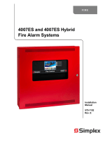
TABLE 2
BOX MOUNTING
3 l/2” OCTAGONAL 1 4” OCTAGONAL 1 4” SQUARE
I
BASE
Yes Yes Yes
Yes Yes Yes
Yes Yes No
4” (10.16 CM) Octagonal
Outlet Box
Not Furnished by Simplex
Wire per NEC Article 370 Base
2098-9211 2098-9536
2098-9637
Base 2098-9201,
2098.9203,
OR
2098-9576
Detector
2098-9202
TABLE 4
Detector
2098-9208
DEHTEEACoTsoR MAX. QTY. OF
BASES PER
INITIATING CIRCUIT
2098-9211
2098qr9211 (SeeTable?kd Note5
2098-9201,
2098-9202,
2098-9203,
2098-9208,
2098059576
with
2098-9738
209&827 (See Aotel)
2098-9637 (SeeTable%md
2098:637 Note5
with
2098-9738
209&827 (See Aote 1)
Notes
TABLE 3
INITIATING
CIRCUITS
OR PANEL
PID
IMODEL NO.)
2120-7012
2120-7013
2120-7014
2120-7015
2120-7019
2120-7023
2120-7024
2120-7031
2120-7032
2120-7033
4002-5001
1. Relay operation cannot be guaranteed unless it is the only device on that zone.
2. Panel compatibility identification marker is the model number of the module or panel.
3. Detector compatibility identification marker is the model number found on the detector label.
4. For detailed interconnection data, see wiring diagrams in Document 841-687.
5. Exceptions for the maximum quantity of 30 bases per initiating circuit are as follows:
lnitiatino Circuit Qtv. of Bases
2120-0523 20
2120-0527 20
2120-7011 18
2120-7022 18
2120-7805 25
2120-7806 25
4001-9403 18
4001-9404 18
4001-9813 18
3
4002-5002
4002-5003
4002-5004
4020-0305
4020-7003
4100-5001
4100-5002
4100-5011
4100-5012

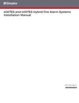
WARNING
Red-labeled detector heads MUST only
be used with red-labeled bases. Use in any other
base will result in a non-functioning detector.
These heads include
- /an LED Y
Heads
2098-9201,
2098-9202,
2098-9203,
OR
2098-9576
Head
098-9208
ea
(P-Wire) (4-Wire)
Base 2098-9637 Base 2098-9536
CAUTION
Install the bases in this instruction in accordance with applicable NFPA standards, local codes, and the
authorities having jurisdiction. Failure to follow these instructions may result in failure of the detector to initiate
an alarm condition. Simplex is not responsible for detectors that have been improperly installed, tested, or
maintained.
CAUTION
CONNECT WIRING TO TERMINALS AS SHOWN. DO NOT LOOP WIRE UNDER TERMINALS. BREAK WIRE
RUN TO PROVIDE SUPERVISION OF CONNECTIONS.
4

power i-l
source &
Base - 2098-9536 Base - 2098-9536 Base - 2098-9536
Head 2098-9201, Head -
- 2098-9201, Head - 2098-9201,
2098-9202, 2098-9202, 2098-9202,
24
VDC
2098-9203, 2098-9203, 2098-9203, EOL Relay
2098-9208, 2098-9208, 2098-9208, 2098-9735
or or or
2098-9576 2098::576 2098-9576 2098-9739
Ll Ll Ll Elk
I w-
L2 L2 L2
r .^
Lm3 I 1x1
r
Relay
2096-9737
(See Note 3)
N/C
N/O
See
Note
5
1
Blk
Note I-
-1
2 Elk
Notes: 1. Refer to wiring diagrams (841-687) provided with system panel for proper panel connections.
2. If used, remote LED (2098-9808) is polarized; observe color-coded wiring. DO NOT USE RELAY if LED is
3. DO NOT USE REMOTE LED when relay (2098-9737) is used.
4. Aux. alarm contacts -form C-each rated 1A @ 24VDC or 115VAC, resistive.
5. Aux. alarm contacts - two form C -each rated 3A @ 24VDC or 115VAC, resistive.
6. Refer to wiring diagrams provided with system panel for proper end-of-line resistor value.
2098-9536 BASE CONNECTIONS
Backup 2
ISeeNote3
II
” Primary1
-
Listed
Simplex
Fire Alarm
Control
Panel
2120,
4001,4002,
4020,or4100+
see
Note 2 see RE
Base - 2098-9637 ’ Note2 Base - 2098-9637 Head - 2098-9201,
2098-9202,
2098-9203,
2098-9208,
2092576
Head - 2098-9201,
2098-9202,
2098-9203,
2098-9208,
2098qr9576
Head - 2098-9201,
2098-9202,
2098-9203,
2098-9208,
2096576
Notes: 1. Refer to wiring diagrams (841-687) provided with system panel for proper panel connections.
2. If used, remote LED (2098-9808) is polarized; observe color-coded wiring.
3. It is recommended that the primary-l and the backup-2 lines be in separate wire runs and in compliance with local
requirements.
2098-9637 BASE CONNECTIONS FOR STYLE D (FORMERLY CLASS A) INITIATE CIRCUIT
5

Listed
Simplex
Fire Alarm
Control
Panel
2120,
4001,4002,
1020,or4100+
Head - 2098-9201,
2098-9202,
2098-9203,
2098-9208,
2098qr9578
Head - 20989201,
2098-9202,
2098-9203,
2098-9208,
209E9576
Head - 20989201,
2098-9202,
2098-9203,
2098-9208,
2098qr9576
Notes: 1. Refer to wiring diagrams (841-687) provided with system panel for proper panel connections.
2. If used, remote LED (20989808) is polarized; observe color-coded wiring.
3. Refer to wiring diagrams provided with system panel for proper end-of-line resistor value.
2098-9637 BASE CONNECTIONS FOR STYLE B (FORMERLY CLASS B) INITIATE CIRCUIT
r-
I +
I
I
Listed
Simplex
Fire Alarm
Control
Panel,
2120,
4001,4002,
4020,or4100+
Backup 2 ----__-_ I
I
Primarv 1 I
I I
I I See Note
c I
4
Base - 2098-9637
Relay Module - 2098-9738
Head - 20989201,
2098-9202,
2098-9738
Relay Module
See Note 3
2098-9203,
2098-9208,
Or
2098-9576
Aux. Relay Contacts
Rated 1 A (11 24VDC
Or 115VAC Resistive
J
Note
3
Notes: 1. Refer to wiring diagrams (841-687) provided with system panel for proper panel connections.
2. If used, remote LED (2098-9808) is polarized; observe color-coded wiring.
3. When wiring relay to base, remove resistor (black wire) from base terminal 53. Wire only one base/relay per initiate circuit.
4. For Style D (formerly Class A) initiate circuit, wire per dotted lines and do not use EOL resistor. If Style B (formerly Class
B) initiate circuit, refer to wiring diagrams provided with system panel for proper EOL resistor value.
5. For Style D (formerly Class A) wiring, it is recommended that the primary-l and the backup-2 lines be in separate wire
runs and in compliance with local requirements.
20989637 WITH 20989738
BASE AND RELAY CONNECTIONS FOR STYLE B (FORMERLY CLASS B) OR STYLE D (FORMERLY CLASS A) INITIATE CIRCUIT
6

n-
II
II +
;I
see +
Note
il
1 -
Listed
Simplex
Fire Alarm
Control
Panel
2120,
4001,4002.
020,
or
4100+
Backup 2
----e -----
Primary 1
Aux. Relay Contacts
Rated 1 A ((I 24VDC
Or 115VAC Resistive
Base - 2098-9211 2098-9738
Blk Relay Module - 2098-9738 Relay Module
Head - 2098-9201, See Note 3
2098-9202,
2098-9203,
2098-9208,
or
2098-9576
Notes: 1. Refer to wiring diagrams (841-687) provided with system panel for proper panel connections.
2. If used, remote LED (2098-9808) is polarized; observe color-coded wiring.
3. When wiring relay to base, cut JW. Wire only one base/relay per initiate circuit.
4. For Style D (formerly Class A) initiate circuit, wire per dotted lines and do not use EOL resistor. If Style B (formerly Class
B) initiate circuit, refer to wiring diagrams provided with system panel for proper EOL resistor value.
5. For Style D (formerly Class A) wiring, it is recommended that the primary-l and the backup-2 lines be in separate wire
runs and in compliance with local requirements.
2098-9211 WITH 2098-9738
BASE AND RELAY CONNECTIONS FOR STYLE B (FORMERLY CLASS 8) OR STYLE D (FORMERLY CLASS A) INITIATE CIRCUIT
Listed
Simplex
Fire Alarm
Control
Panel
2120,
4001.4002.
4020,
or 4100+
Backup 2
ISeeNote3
r!
” Primary1
r Cm Nntr 3
zz
4 An-
/
See Red
_. . ^
-s
Note 2
/
WhtlBlk Base - 20989211
Head - 2098-9201,
2098-9202, 2098-9202, 2098-9202,
2098-9203, 2098-9203, 2098-9203,
20989208, 2098-9208, 2098-9208,
or or or
2098-9576 2098-9576 2098-9576
Head - 2098-9201, Head - 2098-9201,
Notes: 1. Refer to wiring diagrams (841-687) provided with system panel for proper panel connections.
2. If used, remote LED (2098-9808) is polarized; observe color-coded wiring.
3. It is recommended that the primary-l and the backup-2 lines be in separate wire runs and in compliance with local
requirements.
2098-9211 BASE CONNECTIONS FOR STYLE D (FORMERLY CLASS A) INITIATE CIRCUIT
7

4
See
Note 1
i m
Listed
Simplex
Fire Alarm
Control
Panel
2120,
1001,4002
4020, or
4100+ Base - 2098-9211
Head - 2098-9201. Base - 2098-9211
Head - 2098.9201.
2098-9202; 2098-9202,
2098-9203, 2098-9203,
2098-9208, 2098-9208,
or or
2098-9576 2098-9576
Head - 2098-9201,
2098-9202,
2098-9203,
2098-9208,
209:;576
Notes: 1. Refer to wiring diagrams (841-687) provided with system panel for proper panel connections.
2. If used, remote LED (2098-9808) is polarized; observe color-coded wiring.
3. Refer to wiring diagrams provided with system panel for proper end-of-line resistor value.
2098-9211 BASE CONNECTIONS FOR STYLE B (FORMERLY CLASS B) INITIATE CIRCUIT
See
Note
See
lote 1
Listed
Simplex
rire Alarm
Control
Panel
2120,
001,4002,
4020, or
4100+
Red
See
Note
2
I
,
;___________________----~:
Base-2098-9637
Relay Module-2098-9827
Head-2098-9201,
2098-9202,
2098-9203,
2098-9208,
or
EOL
Resistor
(if used)
Aux. Relay Contacts, Each
Rated 1 Amp at 30VDC or
0.5 Amp at 12OVAC, Resistive
See
Note
3
2098-9576 I
2098-9827 Relay Module
See Note 3
Notes: 1. Refer to wiring diagrams (841-687) provided with system panel for proper panel connections.
2. If used, remote LED (2098-9808) is polarized; observe color-coded wiring.
3. When wiring relay to base, remove resistor (black wire) from base terminal S3. Wire only one base/relay per initiate circuit.
4. For Style D (formerly Class A) initiate circuit. wire per dotted lines and do not use EOL resistor. If Style
initiate circuit, refer to wiring diagrams provided with system panel for proper EOL resistor value. B (formerly Class B)
5. For Style D (formerly Class A) wiring, it is recommended that the primary-l and the backup-2 lines be in separate wire
runs and in compliance with local requirements.
2098-9637 with 2098-9827
BASE AND RELAY CONNECTIONS FOR STYLE B (FORMERLY CLASS B) OR STYLE D (FORMERLY CLASS A) INITIATE CIRCUIT
a

+
c
m
Listed
Sim lex
i F~onfrIrnI
Panel
2120,
4\;204;;2
4106+ - WhtiBlkj ’ Base-2098-9211
Relav Module-2098-9827
EOL
Resistor
(if used)
I
(+)Red Vi0
Blk Blu
GV
__ .
-5
Nii-
4c
-5 N/O
Aux. Relay Contacts, Each
Rated 1 Amp at 30VDC or
0.5 Amp at 1 POVAC, Resistive
Head-20989201,
2098-9202,
2098-9203,
2098-9208,
209:9576 2098-9827 Relay Module
-
See Note 3
Notes: 1. Refer to wiring diagrams (841-687) provided with system panel for proper panel connections.
2. If used, remote LED (2098-9808) is polarized; observe color-coded wiring.
3. When wiring relay to base, cut JW. Wire only one base/relay per initiate circuit.
4. For Style D (formerly Class A) initiate circuit. wire per dotted lines and do not use EOL resistor. If Style B (formerly Class B)
initiate circuit, refer to wiring diagrams provided with system panel for proper EOL resistor value.
5. For Style D (formerly Class A) wiring, it is recommended that the primary-l and the backup-2 lines be in separate wire
runs and in compliance with local requirements.
2098-9211 WITH 20989827
BASE AND RELAY CONNECTIONS FOR STYLE B (FORMERLY CLASS B) OR STYLE D (FORMERLY CLASS A) INITIATE CIRCUIT
LIMITATIONS OF SMOKE DETECTORS
The smoke detectors used with these bases are designed to activate and initiate emergency action, but will do so
only when used in conjunction with other equipment. They are designed for installation in accordance with NFPA
standards 72-l 990 and 72E.
Smoke detectors will not work without power. AC or DC powered smoke detectors will not work if the power supply
is cut off for any reason.
Smoke detectors will not sense fires which start when smoke does not reach the detectors. Smoke from fires in
chimneys, in walls, on roofs or on the other side of closed doors may not reach the smoke detector and alarm it.
A detector may not detect a fire developing on another level of a building. For this reason, detectors should be
located on every level of a building.
Smoke detectors have sensing limitations, too. Ionization detectors are better at detecting fast, flaming fires than
slow, smoldering fires. Photoelectric detectors sense smoldering fires better than flaming fires. Because fires
develop in different ways, and are often unpredictable in their growth, neither type of detector is always best, and a
given detector may not always provide warning of a fire. In general, detectors cannot be expected to provide warning
for fires resulting from inadequate fire protection practices, violent explosions, escaping gases, improper storage of
flammable liquids like cleaning solvents, other safety hazards, or arson.
Smoke detectors cannot last forever. Smoke detectors contain electronic parts. Even though detectors are made to
last for many years, any of these parts could fail at any time. Therefore, test your smoke detector system per NFPA
72E & 72H at least semi-annually. Clean and take care of your smoke detectors regularly.
9


PER-21 -007 (575285)
Ed 2 93
/