Page is loading ...

Jeep Grand Cherokee 93-98 ZJ 1.5” Lift Kit
Thank you for choosing Rough Country for all your suspension needs.
Rough Country recommends a certified technician install this system. In addition to these instructions, professional
knowledge of disassemble/reassembly procedures as well as post installation checks must be known. Attempts to install
this system without this knowledge and expertise may jeopardize the integrity and/or operating safety of the vehicle.
Please read instructions before beginning installation. Check the kit hardware against the parts list on this page. Be sure
you have all needed parts and know where they go. Also please review tools needed list and make sure you have
needed tools. Always wear safety glasses.
PRODUCT USE INFORMATION
As a general rule, the taller a vehicle is, the easier it will roll. Seat belts and shoulder harnesses should be worn at all
times. Avoid situations where a side rollover may occur.
Generally, braking performance and capability are decreased when larger/heavier tires and wheels are used. Take this
into consideration while driving. Do not add, alter, or fabricate any factory or after-market parts to increase vehicle height
over the intended height of the Rough Country product purchased. Mixing component brands is not recommended.
Rough Country makes no claims regarding lifting devices and excludes any and all implied claims. We will not be re-
sponsible for any product that is altered.
Due to inconsistency of vehicles when manufactures and various options available, the amount of actual lift gained by
this lift kit could vary.
This suspension system was developed using a 30 x 9.50 x 15 tire with factory wheels. Larger tire and wheel combina-
tions may increase leverage on suspension, steering and related components. Consider the additional stress you could
be adding on the OE components, when selecting combinations larger than OE.
NOTICE TO DEALER AND VEHICLE OWNER
Any vehicle equipped with any Rough Country product should have a “Warning to Driver” decal installed on the inside of
the windshield or on the vehicle’s dash. The decal should act as a constant reminder for whoever is operating the vehi-
cle of its unique handling characteristics.
13mm wrench
13mm socket
15mm wrench
15mm socket
16mm wrench
18mm socket
18mm wrench
21mm wrench
21mm socket
19mm wrench
19mm socket
Floor Jack
TORQUE SPECS:
Size Grade 5 Grade 8
3/8” 30 ft/lbs 35 ft/lbs
7/16” 45 ft/lbs 60 ft/lbs
1/2” 65 ft/lbs 90 ft/lbs
9/16” 95 ft/lbs 130 ft/lbs
Class 8.8 Class 10.9
12MM 55ft/lbs 75ft/lbs
13/16” Socket
9/16” Socket
7/16” Drill Bit
T55 Torx Head
T50 Torx head
Jack stands
Safety Glasses
Drill
WD40
Coil Spring Compressor
TOOLS NEEDED:
92168520A
*1685BAG3*
1685BAG3

KIT CONTENTS

FRONT INSTALLATION
INSTALLATION INSTRUCTIONS
1. Park the vehicle on a level surface and chock the rear tires. Jack up the front of the vehicle and support the front of
the vehicle with jack stands. Remove the tires and wheels. Remove the stock shock absorbers.
2. Place the floor jack underneath the axle. Jack up the floor jack to apply a slight load to the coil springs.
3. Remove the upper sway bar bushing assembly. Remove the coil clip on the lower coil mount. Save the stock hard-
ware, it will be reused. Lower the jack to unload the coil springs. But do not totally remove the floor jack.
4. Remove the stock coil spring. Repeat this procedure for the opposite side.
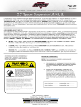
5. Remove the stock bump stop. See Photo 1.
6. Remove the bump stop mounting cup as shown. See Photo 2.
7. Install coil spacer as shown. A rubber hammer may be used to get the spacer into position. See Photo 3.
8. After positioning the spacer flush with the stock rubber mount, reinstall the bump stop mounting cup that was re-
moved previously.
9. Install the stock coil spring. The new bump stop must be installed after the coil is in position. This is done by putting
the new bump stop inside the coil spring, then install the coil.
10. After the coil is installed, apply a slight load to the coil spring and position the bump stop in the retaining cup. With a
pry bar and using the coil wrap as leverage, push the bump stop up into the cup until it snaps into place. See Photo
4.
11. Install the coil spring retaining clip and torque fastener
12. Repeat on opposite side. Note: Reinstallation of coil springs may need to be performed with a strut compres-
sor. If so load coils with strut compressor and install coil. After install remove the strut compressor.
13. Jack up the axle to apply a slight load to the front end. Reinstall the sway bar end links to the sway bar.
14. Install the front shock absorbers with the supplied bushings and washers.
15. Install the wheels and tires. Remove the jack stands and lower the vehicle to the ground. Torque the lug nuts to fac-
tory specifications.
PHOTO 3 PHOTO 4
PHOTO 1 PHOTO 2

REAR INSTALLATION
1. Chock the front tires and jack up the rear of the vehicle. Remove the wheels and tires. Remove the stock shock ab-
sorbers
2. With the floor jack still in place, remove the sway bar link from the axle mount.
3. With the sway bar links disconnected, lower the axle with the floor jack to allow for coil spring removal.
4. Remove the coil spring and place the coil spacer on the upper mount. Reinstall the coil spring.
5. Repeat for opposite side.
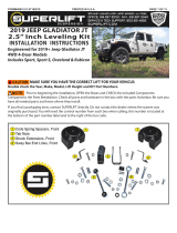
6. Jack up the axle with the floor jack and install the new shock absorbers part # 658721 with the supplied bushings
and sleeves. The steel sleeve will be installed in the lower mount, which would be the body end of the shock.
7. Reinstall the sway bar to axle links.
8. Install the wheels and tires. Lower the vehicle to the ground. Torque the lug nuts to factory specifications.
POST INSTALLATION INSTRUCTIONS
1. Check all fasteners for proper torque. Check to ensure there is adequate clearance between all rotating, mobile,
fixed and heated members. Check steering gear for interference and proper working order. Test brake system.
2. Perform steering sweep. Check to ensure brake hoses have sufficient slack and will not contact rotating, mobile, or
fixed members. Adjust lines/brackets to eliminate interference and maintain proper working order. Failure to per-
form inspections may result in component failure.
3. Bump stops and extensions must be in place on all vehicles! Note: allowing suspension to over extend by neglect-
ing to install or maintain stops and extensions may cause serious damage to OE and related components.
4. Re torque all fasteners after 500 miles. Visually inspect components and re torque fasteners during routine vehicle
service.
MAINTENANCE INFORMATION
It is the ultimate responsibility for the operator / owner to have all bolts/nuts checked for tightness after the first 100
miles and then every 1000 miles. Wheel alignment, steering system, suspension and driveline systems must be in-
spected by a qualified professional mechanic at least every 3000 miles.
By purchasing any item sold by Rough Country, LLC, the buyer expressly warrants that he/she is in compliance with all
applicable , State, and Local laws and regulations regarding the purchase, ownership, and use of the item. It shall be
the buyers responsibility to comply with all Federal, State and Local laws governing the sales of any
items listed, illustrated or sold. The buyer expressly agrees to indemnify and hold harmless Rough
Country, LLC for all claims resulting directly or indirectly from the purchase, ownership, or use of the
items.
/