Page is loading ...

www.ReadyLIFT.com - Phone: (877) 759-9991
69-23350-IM-AB
(877) 759-9991
MON-FRI 7AM-4PM PST
OR
EMAIL: support@readylift-ami.COM
WEBSITE: ReadyLIFT.COM
**Please retain this document in your vehicle at all times.**
IF your ReadyLIFT® product has a damaged or missing
part, please contact customer service directly and
a new replacement part will be sent to you immediately.
For warranty issues, please return to the place of
installation and contact ReadyLIFT.
Limited Lifetime Warranty
This unique product warranty proves our commitment to the quality and reliability of every product that
ReadyLIFT manufactures. The ReadyLIFT product warranty only extends to the original purchaser of any
ReadyLIFT product, if it breaks, we will give you a new part. Warranty does not apply to discontinued parts.
Our Limited Lifetime Warranty excludes the following ReadyLIFT items; bushings, bump stops, ball joints, tie
rod ends, heim joints and shock absorbers. These parts are subject to wear and are not considered defective
when worn. They are warranted for 12 months from the date of purchase for defects in workmanship.
This product warranty is voided if the vehicle is not aligned after kit installation and proper maintenance is
routinely done.
Product purchased directly from ReadyLIFT has a 90 day return policy on uninstalled products from the date
of purchase (may be subject to restocking fee). Uninstalled product returns must be in the original
ReadyLIFT packaging. Please call (877) 759-9991 to get an RGA# for any return. Customer is responsible
for shipping costs back to ReadyLIFT. Returns without RGA# will be refused. Contact ReadyLIFT
directly about any potentially defective parts prior to removal from vehicle.
ReadyLIFT products are NOT intended for off-road abuse. Any damage or failure as a result from off-road
abuse voids the warranty of the ReadyLIFT product. ReadyLIFT is NOT responsible for any subsequent
damages to any related vehicle parts due to misuse, abuse, improper installation, or lack of maintenance.
Furthermore, ReadyLIFT reserves the right to change, modify or cancel this warranty without prior notice.
69-23350 2023-Up Ford Super Duty 3.5” SST Kit

www.ReadyLIFT.com - Phone: (877) 759-9991
2 69-23350-IM-AB
READ INSTRUCTIONS THOROUGHLY AND COMPLETELY BEFORE BEGINNING INSTALLATION.
INSTALLATION BY A CERTIFIED PROFESSIONAL MECHANIC IS HIGHLY RECOMMENDED.
READYLIFT® IS NOT RESPONSIBLE FOR ANY DAMAGE OR FAILURE RESULTING FROM IMPROPER INSTALLATION.
Safety Warning
MISUSE OF THIS PRODUCT COULD LEAD TO INJURY OR DEATH.
Suspension systems or components that enhance the on and off-road performance of your vehicle may cause
it to handle differently than it did from the factory. Extreme care must be used to prevent loss of control or
vehicle rollover during abrupt maneuvers.
Always operate your vehicle at reduced speeds to ensure your ability to control your vehicle under all driving
conditions. Failure to drive safely may result in serious injury or death to driver and passengers.
Driver and passengers must ALWAYS wear your seat belts, avoid quick sharp turns and other sudden
maneuvers. ReadyLIFT Suspension does not recommend the combined use of suspension lifts, body lifts, or
other lifting devices.
You should never operate your vehicle under the influence of alcohol or drugs.
Constant maintenance is required to keep your vehicle safe. Thoroughly inspect your vehicle before and after
every off-road use.
It is the responsibility of the retailer and/or the installer to review all state and local laws, with the end user
of this product, related to bumper height laws and the lifting of their vehicle before the purchase and
installation of any ReadyLIFT products.
It is the responsibility of the driver/s to check their surrounding area for obstructions, people, and animals
before moving the vehicle.
All raised vehicles have increased blind spots; damage, injury and/or death can occur if these instructions are
not followed.
.
Installation Warning
All steps and procedures described in these instructions were performed while the vehicle was properly
supported on a two post vehicle lift with safety jacks.
Use caution during all disassembly and assembly steps to insure suspension components are not over
extended causing damage to any vehicle components and parts included in this kit.
Included instructions are guidelines only for recommended procedures and are not meant to be definitive.
Installer is responsible to insure a safe and controllable vehicle after performing modifications.
ReadyLIFT Suspension recommends the use of an OE Service Manual for model/year of vehicle when
disassembly and assembly of factory and related components.
Unless otherwise specified, tighten all bolts and fasteners to standard torque specifications listed within the
OE Service Manual.
Suspension components that use rubber or urethane bushings should be tightened with the vehicle at normal
ride height. This will prevent premature wear or failure of the bushing and maintain ride comfort.
Larger tire and wheel combinations may increase leverage on suspension, steering, and related components.
Due to payload options and initial ride height variances, the amount of lift is a base figure. Final ride height
dimensions may vary in accordance to original vehicle ride height. Always measure the vehicle ride height
prior to beginning installation.
SAEJ2492 Warning
By installing this product, you acknowledge that the suspension of this vehicle has been modified. As a result, this
vehicle may handle differently than that of factory-equipped vehicles. As with any vehicle, extreme care must be used to
prevent loss of control or roll-over during sharp turns or abrupt maneuvers. Always wear seat belts, and drive safely,
recognizing that reduced speeds and specialized driving techniques may be required. Failure to drive this vehicle safely
may result in serious injury or death. Do not drive this vehicle unless you are familiar with its unique handling
characteristics and are confident of your ability to maintain control under all driving conditions. Some modifications (and
combinations of modifications) are not recommended and may not be permitted in your state. Consult your owner’s
manual, the instructions accompanying this product, and state laws before undertaking these modifications. You are
responsible for the legality and safety of the vehicle you modify using these components.

www.ReadyLIFT.com - Phone: (877) 759-9991
3 69-23350-IM-AB
Due to payload options and initial ride height variances, the amount of lift is a base figure. Final ride height
dimensions may vary in accordance to original vehicle ride height. Always measure the vehicle ride height
prior to beginning installation.
A lifted vehicle may have different headlight aim performance. ReadyLIFT recommends marking and
recording the headlight beam position before kit installation and then adjusting, if necessary, the headlamps
to the same height settings after kit installation. Set the vehicle on a level surface 10' to 15’ from a solid wall
or garage door. (This is a general distance with some manufacturers requiring different distances.) Note the
top height of the low beam's bright spot, the top of the most intense part of the beam, for driver and
passenger side. Height may vary from side to side. Repeat this procedure and adjust after lift kit is
installed. Adjust if the aim is off by turning the adjusters gradually (a quarter of a turn) and looking to see
where the new alignment falls. It may be easier to block one headlamp while adjusting the other. Consult
the owner operation manual for procedures to adjust headlights - many automakers offer headlight aiming
specs. Some states have their own specifications when it comes to headlight aim, so it’s best to follow those
rules when alighting headlights.
This suspension system was developed using a 35x12.5 tire with an offset of 0”. If
wider tires are used, offset wheels may be necessary and trimming may be required.
Factory wheels can be used but are not recommended with tires over 12.5” wide.
The stock spare rim can be run in an emergency - exercise extreme caution under
stock spare tire operating conditions. Please note that, if running the spare factory
tire, it is done for short distances and a speed not to exceed 45mph or damage to
differentials may occur.
IMPORTANT NOTE:
When selecting a wheel, 18” and larger must be used. Factory 17” and 18” will not
work. Factory 20” wheels may be reused.
TEST FIT YOUR WHEEL AND TIRE PACKAGE BEFORE INSTALLATION.
Due to the nature of Ford’s lane keeping/lane departure features, it may be necessary
to have the vehicles camera and sensors
recalibrated to ensure these systems functions as they did prior to install. Please
contact your local Ford dealership to set up an
appointment.
CAUTION: Use extreme care while working on POWERBOOST vehicles. High Voltage
wires are wrapped in orange covering; care should be taken to avoid damaging the
coating of these wires. Damage to these wires can result in SERIOUS INJURY or
DEATH.

www.ReadyLIFT.com - Phone: (877) 759-9991
4 69-23350-IM-AB
PRE-INSTALLATION MEASUREMENTS:
It is imperative that you record the following measurements and factory components
in the tables below. ReadyLIFT tests and records as much data from each application
as available at the time of product development. Vehicle manufacturers may change
components or add models with different options. Recording and not exceeding the
fender-to-hub-center ReadyLIFT calls out will ensure the lift on the vehicle is correct.
These measurements will affect the performance of this lift kit. Failure to ensure
proper stock conditions may result in over lifting, causing premature failure of axles,
CV boots and drivetrain. Over lifting a vehicle will also result in an incorrect wheel
alignment. This will wear tires incorrectly. Incorrect alignment will cause poor vehicle
handling issues including but not limited to under steer. Over lifting will also cause a
shock top off condition resulting in poor ride quality accompanied by pops and clunks
which are symptoms of prematurely wearing components.
Failure to adjust head lamps may cause dangerous driving conditions for you and
other drivers on the road. Record the head lamp position before the installation of this
lift or leveling kit and adjust to original factory position after the completion to ensure
a safe and enjoyable experience.
VEHICLE HEIGHT MEASURMENTS
**MEASUREMENT IS TO BE PERFORMED FROM CENTER OF HUB TO FENDER
EDGE STRAIGHT UP FROM HUB.**
RECORD HEAD LAMP MEASURMENTS
Driver
Before
Driver
After
Passenger
Before
Passenger
After
Front
Rear
Driver
Before
Driver
After
Passenger
Before
Passenger
After

www.ReadyLIFT.com - Phone: (877) 759-9991
5 69-23350-IM-AB
BILL OF MATERIALS
DESCRIPTION QTY
COIL SPACER 2
POLY RING 2
SHOCK RELOCATION, DVR 1
SHOCK RELOCATION, PAS 1
FRONT TRACK BAR DROP 1
16MM DRIVELINE SPACER 1
FRONT BUMPSTOP EXTENSIONS 2
SLEEVE: RADIUS ARM DROP 2
U-BOLT 4
TAPERED REAR LIFT BLOCK, DRIVER 1
TAPERED REAR LIFT BLOCK, PASSENGER 1
FRONT SWAY BAR DROP, DRIVER 1
FRONT SWAY BAR DROP, PASSENGER 1
NUT PLATE, DRIVER 1
NUT PLATE, PASSENGER 1
RADIUS ARM DROP BRACKET, DRIVER 1
RADIUS ARM DROP BRACKET, PASSENGER 1
BRAKE LINE BRACKET, DRIVER 1
BRAKE LINE BRACKET, PASSENGER 1
DESCRIPTION QTY
Shock Relocators 1
M14(2.00) X 80 METRIC HEX SC GR 10.9 ZINC 2
M14(2.00) UNITORQUE LOCKNUT CLASS 10 ZINC 2
14MM HARDENED FLAT WASHER (28MM OD) YELLOW
ZINC 4
Driveline Shim 1
7/16-14 X 2 1/4 HEX BOLT J429 GR 8 ZINC II 2
7/16 ASTM F436 HARD WASHER-YELLOW ZINC 2
Swaybar Drops 1
7/16-14 X 1-1/4 HEX CAP GR8 ZINC II 4
7/16-14 TOPLOCK GRADE C ZINC 4
7/16 FL WSHR SAE ZINC 8
Brakeline Drops 2
5/16-18 X 3/4 HEX BOLT J429 GR 8 ZINC II 1
5/16-18 TOPLOCK GRADE C ZINC 1
5/16 ASTM F436 HARD WASHER (A325) **IMPORT**
YELLOW ZINC 2
Bump Stop 1
8mm- 1.25 HEX NUT Gr. 10.9 4
8mm SAE FLAT WASHER 2
Radius Arm Drop Bracket 1
M18(2.50) X 130 GR 10.9 HCS ZINC PARTIAL THREAD 2
M18(2.50) X 40 METRIC HEX SC GR 10.9 ZINC 2
M18(2.50) PRV TQ LCKNT CLASS 10 ZINC 2
M18 FLAT WASHER HARD HV200 DIN 125 ZINC YELLOW 6
M18 DIN 127 METRIC SPLIT LOCKWASHER ZB 2

www.ReadyLIFT.com - Phone: (877) 759-9991
6 69-23350-IM-AB
Before starting installation:
ReadyLIFT Suspension highly recommends that the installation of this
product be performed by a professional mechanic with experience working on and installing suspension
products. Professional knowledge and skill will typically yield the best installation results. If you need an
installer in your area, please contact ReadyLIFT Suspension Customer Service or check out the dealers tab
on our Website for authorized installers .
INSTALLATION BY A PROFESSIONAL IS HIGHLY RECOMMENDED.
• A Factory Service Manual for your specific Year / Make / Model is highly recommended for reference
during installation.
• All lifted vehicles may require additional driveline modifications and / or balancing.
• A vehicle alignment is REQUIRED after installation of this product.
• Speedometer / Computer recalibration is required if changing +/- 10% from factory tire diameter.
• A vehicle lift or hoist greatly reduces installation time. Installation time estimates are based on an
available vehicle hoist.
• Vehicle must be in excellent operating condition. Repair or replace any and all worn or damaged
components prior to installation.
ReadyLIFT recommends all steps and procedures described in these instructions be
performed while the vehicle is properly supported on a two post vehicle lift with
safety jacks.
Otherwise, park vehicle on a clean flat surface and block the rear wheels for safety.
Engage the parking brake.
Disconnect the vehicle power source at the ground terminal on the battery.
Lock the steering wheel in the straight forward position with the column lock or
steering wheel locking device.
Raise the front of the vehicle and support with safety jack stands at each frame rail
behind the lower control arms.

www.ReadyLIFT.com - Phone: (877) 759-9991
7 69-23350-IM-AB
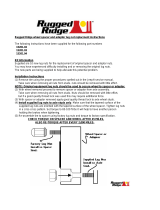
Place car in neutral. Remove the front
wheels. Raise the axle using the floor
jacks to remove the tension from the
shocks.
Remove the track bar bolt from the driver
side frame mount.
Retain the factory hardware.
Remove the sway bar from the frame
mounts, frame brake line bracket and OE
shocks. (both sides).
Lower the front axle as far as possible and
Remove the spring
NOTE: MARK OR NOTE THE APRING
ORIENTATION PRIOR TO REMOVAL.
Remove OE spring isolator.
Remove the vacuum line from the top of
the radius arm located on the driver side.
Use a jack to support the radius arm. The
rear radius arm pivot bolts and hardware
on passenger and driver sides at the same
time.
Retain the factory hardware.
Lower the jack and let the radius arm
drop out of the OE mounting pocket.
Insert the radius arm drop down brackets
into the mounting pocket.
OE Sway Bar Mount
OE Radius Arm
OE Pocket

www.ReadyLIFT.com - Phone: (877) 759-9991
8 69-23350-IM-AB
Secure the radius arm drop down bracket
using the supplied 18mm X 130mm bolts,
sleeves and hardware.
Slide the nut plate, into the frame. Using
the supplied 18mm X 40mm bolts, washer
and split washer, Install the bolt through
the radius arm drop bracket, rear
crossmember and nut plate.
Torque the M18 hardware to 250 ft-lb.
Carefully raise the radius arm into the drop
bracket and secure it using the previously
removed OE hardware.
Do not tighten at this point.
Install the supplied poly ring, coil spring
spacer, OE isolator and coil spring.
Be sure to line up the previously applied
coil spring reference mark.
18mm x 40mm, split
washer, nut plate
18mm x 130mm
And Sleeve
Radius Arm Drop
Down Bracket
OE hardware
Poly ring
Coil Spacer
OE Isolator

www.ReadyLIFT.com - Phone: (877) 759-9991
9 69-23350-IM-AB
Install the shock relocation brackets into
the lower shock mounts using the OE
hardware. Install the lower shock mount
into the shock relocation brackets using
the supplied 14mm-2.0 X 80mm bolts,
washers and locking nuts.
Do not tighten at this point.
NOTE:IF INSTALLING A KIT THAT CONTAINS
SHOCKS, FORGO THIS STEP AND PROCEED TO
THE NEXT.
Unbolt and remove the OE shock from the
vehicle. Install the OE or new shock using
the previously removed OE hardware.
Remove the factory front bump stop from
the bump stop mounting cup. Pliers and a
back and forth rocking motion will assist in
removal of the bump stop.
Unbolt the bump stop mounting cup from
the frame of the vehicle. Install the bump
stop extension into the OE bump stop
mounting cup hole.
Install the OE bump stop cup to the bump
stop extension using the supplied 8mm nut
and washer.
Torque the M8 hardware to 25 ft-lb.
Install the factory bump stop into the
bump stop mounting cup.
OE or New Shock

www.ReadyLIFT.com - Phone: (877) 759-9991
10 69-23350-IM-AB
Remove the cast track bar mount on driver
side of frame.
Retain the factory hardware.
Install track bar drop bracket using thread
locker and the factory hardware. Do not
install track bar at this time.
Torque the bracket hardware to 95 ft-lb.
Remove the OE brake line bracket from
the frame.
Retain the factory hardware.
Install the brake line drop bracket to the
original hole in the frame rail using the
factory bolt.
Pull the flexible OE brake line through the
axle mounted lower brake line bracket
approximately 1”-2”.
Gently pull the metal brake line down while
lining up the brake line to the new bracket
using the supplied 5/16” x 3/4” bolts,
washers, and nuts.
Torque mounting hardware to 10 ft-lbs.
Install the sway bar drops to the OE sway
bar mounting studs on the frame using the
factory hardware.
Raise the sway bar into place and secure
with the supplied 7/16”-14 X 1-1/4” bolts,
washers and locking nuts.
Torque factory mounting nuts to 50 ft-lbs.
Torque the 7/16” hardware to 70 ft-lbs.
Brake line Bracket
Sway bar
drop bracket
Trackbar Bracket
OE Hardware
OE Brake line
Bracket

www.ReadyLIFT.com - Phone: (877) 759-9991
11 69-23350-IM-AB
Install wheels and torque to
manufacturer’s specifications.
Lower the vehicle to the ground.
Install the track bar into the track bar
bracket using the OE bolt.
Torque the factory bolt to 406 ft-lb.
Torque the radius arm bolts to 225 ft-lb.
Rear Installation
Block the front tires and raise the rear of the vehicle using a suitable jack.
Support with jack stands at each frame rail in front of the rear leaf spring hangers.
Unscrew the rear axle vent tube to
separate the rear brake line bracket from
the rear axle.
If your vehicle is equipped with factory
sway bar, unbolt it from the end links.
Unbolt and remove the end links from the
vehicle.
OE Bolt
OE Trackbar
Recheck all hardware for tightness after off
road use.

www.ReadyLIFT.com - Phone: (877) 759-9991
12 69-23350-IM-AB
If required, remove the (2) bolts that
secure the center drive shaft bearing.
Lower bearing and the install the carrier
bearing spacer using 7/16”-14 X 2 1/4”
bolts and washers.
Torque the 7/16” hardware to 55 ft-lbs.
Remove the shocks on both sides of the
vehicle.
Support the rear axle with a floor jack and
remove the U-bolts on the driver side.
Slightly loosen the U-bolts on the
passenger side.
Lower the rear axle and remove the factory
block.
Install the supplied lift block. Use your floor
jack to raise the axle to the spring making
sure the pin on the factory leaf spring
assembly fits into the hole on the lift block.
Install the supplied U-bolts, washers and hi
-nuts.
Do not torque the hi-nuts at this time.
Repeat the installation on the other side of
the vehicle.
Now would be a good time to inspect the
rear shocks for damage or fluid leakage.
Replace if necessary.
Install the OE or new rear shocks using the
previously removed OE hardware.
Torque the shock hardware to 90 ft-lbs.
Install the rear axle vent tube to secure
the rear brake line bracket to the rear axle.
Lift Block
OE or New Shock
OE Lift Block
OE U bolts

www.ReadyLIFT.com - Phone: (877) 759-9991
13 69-23350-IM-AB
With everything tightened and torque to the specified specifications, install front tires
and lower vehicle.
Reconnect the battery ground terminal.
With the steering wheel centered, turn the tie rod ends until the tires are straight. If
the steering wheel is not centered properly, the ABS/traction control lights may
activate. Turn the wheels from lock to lock and make sure the brake lines and ABS
routing clears all suspension components adequately. Reposition if necessary.
Have wheel alignment performed by qualified alignment technician. Have the
alignment set to the recommended specs at the end of the instructions.
NOTES: On completion of the installation, have the suspension and headlights realigned.
After 100 miles recheck for proper torque on all newly installed hardware. Recheck all
hardware for tightness after off road use.
Reinstall the wheels and tires and lower
the vehicle to the ground. Torque lug nuts
to manufacturer specification.
Torque the U-bolts to 120 ft-lbs.
Re-check the wheel lug torque on all four
wheels at this time.
Re-check all hardware (both the front and
the rear) for proper installation and torque.
If you wish, you may trim the excess u-bolt
thread length. If you do this you should
leave approximately one inch of thread
exposed after the U-bolts are torqued.
Trim

www.ReadyLIFT.com - Phone: (877) 759-9991
14 69-23350-IM-AB
FAILURE TO PERFORM THE POST INSPECTION CHECKS MAY RESULT IN VEHICLE
COMPONENT DAMAGE AND/OR PERSONAL INJURY OR DEATH TO THE DRIVER
AND/OR OTHERS.
Final Checks & Adjustments
Once the vehicle is lowered to the ground, check all parts which have rubber or urethane components to
ensure proper torque. Torque lug nuts to the wheel manufacturer specs. Move vehicle backwards and
forwards a short distance to allow suspension components to adjust. Turn the front wheels completely left
then right and verify adequate tire, wheel, brake line, and ABS wire clearance. Test and inspect steering,
brake and suspension components for tightness and proper operation. Inspect brakes hoses and ABS lines for
adequate slack at full extension, adjust as necessary.
RECHECK ALL HARDWARE FOR PROPER TORQUE VALUES AFTER 500 MILES, AND THEN
PERIODICALLY AT EACH SERVICE INTERVAL THERAFTER.
Vehicle Handling Warning
Increasing the height of your vehicle raises the center of gravity and can affect stability and control. Use
caution on turns and when making steering corrections.
Vehicles with larger tires and wheels will handle differently than stock vehicles. Take time to familiarize
yourself with the handling of your vehicle.
Wheel Alignment/Headlamp Adjustment
It is necessary to have a proper and professional wheel alignment performed by a certified alignment
technician. Align the vehicle to factory specifications. It is recommended that your vehicle alignment be
checked after any off-road driving.
In addition to your vehicle alignment, for your safety and others, it is necessary to check and adjust your
vehicle headlamps for proper aim and alignment. If the vehicle is equipped with active or passive safety/
collision monitoring and/or avoidance systems including, but not limited to, camera- or radar-based systems,
check and adjust your vehicle’s systems for proper aim and function.
RECOMMENDED ALIGNMENT SPECS
Front Driver Passenger Tolerance Total / Split
Camber -1.5 -1.5 +/- 0.5 +0.0
Caster +3 +3 +/- 0.5 +0.0
Toe +.05 +.05 +/-0.05 +.14
/