Page is loading ...

JEEP JK 6” 2 DR X-SERIES SUSPENSION KIT
Thank you for choosing Rough Country for your suspension needs.
Rough Country recommends a certified technician install this system. In addition to these instructions, professional
knowledge of disassemble/reassembly procedures as well as post installation checks must be known. Attempts to install
this system without this knowledge and expertise may jeopardize the integrity and/or operating safety of the vehicle.
Please read instructions before beginning installation. Check the kit hardware against the parts list. Be sure you have all
needed parts and know where they go. Also please review tools needed list and make sure you have needed tools.
PRODUCT USE INFORMATION
As a general rule, the taller a vehicle is, the easier it will roll. Seat belts and shoulder harnesses should
be worn at all times. Avoid situations where a side rollover may occur. Generally, braking performance and capability are
decreased when larger/heavier tires and wheels are used. Take this into consideration while driving. Do not add, alter, or
fabricate any factory or after-market parts to increase vehicle height over the intended height of the Rough Country prod-
uct purchased. Mixing component brands is not recommended.
Rough Country makes no claims regarding lifting devices and excludes any and all implied claims. We will not be re-
sponsible for any product that is altered.
This kit features Rough Country’s adjustable joint design. Adjustable end tool is included in kit.
Assemble the joints per the separate instruction sheet Part # 92RCJ120 provided
This 6” suspension system was developed using a 37X12.50X17 tire with 4.5” to 4.75” of back spacing on aftermarket
wheels. Stock wheels can be used with this kit with up to a 35x12.5 tire, but different tire manufactures designs may re-
sult in a tire width that could result in contact with the lower control arm and/or front sway bar link in a sharp turn. Please
consult with your tire and wheel expert before purchasing. Also note that if wider tires are desired, offset wheels will be
required.
IMPORTANT NOTE : Upon completing the install of this kit the draglink must be adjusted to cen-
ter the steering wheel BEFORE the vehicle is driven. Failure to do so will cause a computer error, odd han-
dling, and poor performance.
Drive-shafts are available from Rough Country. The stock drive-shafts DO NOT have enough range of motion,
thus the shaft joints bottom out and damage will occur. The stock shafts can NOT be used and new yoke style
shafts are necessary. Additionally on 2012 Models, additional exhaust modification on the passenger side
crossover pipe will be required for adequate clearance on the front driveshaft.
If question exist we will be happy to answer any questions concerning the design, function, and correct use of our prod-
ucts by calling 1-800-222-7023.
NOTICE TO DEALER AND VEHICLE OWNER
Any vehicle equipped with any Rough Country product should have a “Warning to Driver” decal installed on the inside of
the windshield or on the vehicle’s dash. The decal should act as a constant reminder for whoever is operating the vehi-
cle of its unique handling characteristics.
INSTALLING DEALER - it is your responsibility to install the warning decal and forward these installation instructions on
to the vehicle owner for review. These instructions should be kept in the vehicle for its service
Tools Needed:
10mm Wrench 21mm Socket Jack
21mm Wrench Jack Stand Grinder
18mm Wrench 7/16” Wrench 13/32” Drill Bit
18mm Socket 9/16” Wrench Drill
19mm Wrench 9/16” Socket Pitman arm puller
19mm Deep Well Socket Reciprocating Saw
33mm Socket 13/16” Socket
7/8” Wrench
921684X00

Kit Includes:
9246 Fr Coil Springs
9247 Rr Coil Springs
1683XBox1:
2-Fr Upper Adj Arms
2-Fr Lwr Adj Arms
1-Rr Pass Upper Arm
1-Rr Dr Upper Arm
2-Rr Lower Adj Arm
4-Lower Arm Flex Joints
2-Rear Upper Flex Joints
2-Fr Upper Flex Joints
2-Rear Coil Shims
1684XBox2:
1-Fr Track Rod Bracket
1-Rear Track Rod Bracket
2-Fr Brake Lines
2-Rr Brake Lines
1-Pitman Arm
2-Fr Sway Bar Disconnect Links
1-Dr Fr Disconnect Bracket
1-Pass Fr Disconnect Bracket
2-Rear Sway Bar Links
1-1684Bag2
1-1681Bag3
1-1146Bag1
2-Fr Coil Spacers
2-Rr Coil Spacers
1179
1- Fr Adjustable Track Bar
PERF2.26JK– RCX 2.2 Shock Absorbers
1684Bag2:
For Fr Track Rod Bracket:
3-3/8” x 1 1/4” Bolt
3-3/8” Flat Washer
5-3/8” Flange Lock Nuts
1-3/8” X 2 1/2” X 3 1/4” U-bolt
1-14mm x 80mm Bolt
1-14mm Lock Nut
2-14mm Flat Washer
1-Crush Sleeve
For Upper Pass Control Arm:
1-10mm x 80mm Bolt
1-10mm Lock Nut
For Fr Brake Lines:
2-Frame Brackets
2-Brake Clips
4-Crush Washers
For Rear Brake Lines:
2-Frame Brackets
2-Brake Clips
4-Crush Washers
For Rear Track Rod Bracket:
3-3/8” x 1” Bolt
3-3/8” Flat Washers
3-3/8” Flange Lock Nuts
1-14mm x 80mm Bolt
1-14mm x 75mm Bolt
2-14mm Lock Nuts
1-Crush Sleeve
For Rear Coil Spacer
2-Spring Spacer Retainers
2-1/2” x 2 3/4” Bolts
2-1/2” Lock Washers
2-1/2” Flat Washers
1681Bag3:
For Rear Sway Bar Links:
4-Sleeves
4-1/2” x 2 3/4” Bolts
4-1/2” Lock Nuts
8-1/2” Flat Washers
1146Bag1:
For Fr Sway Bar Disconnects:
4-5/16” x 1” Self Tap Bolt
2-Link Ends
2-Mounting Pins
2-1/2” Nut
2-1/2” Flat Washers
2-12mm Jam Nuts
2-12mm Flange Lock Nut
2-Hitch Pin
Poly Bags:

TORQUE SPECIFICATIONS
Size Grade 5 Grade 8
5/16” 15 ft/lbs 20 ft/lbs
3/8” 30 ft/lbs 35 ft/lbs
7/16” 45 ft/lbs 60 ft/lbs
1/2” 65 ft/lbs 90 ft/lbs
9/16” 95 ft/lbs 130 ft/lbs
5/8” 135 ft/lbs 175 ft/lbs
3/4” 185 ft/lbs 280 ft/lbs
Metric (Grade) 8.8 10.9 12.9
14MM 85ft/lbs 120ft/lb. 145ft/lbs
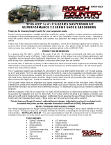
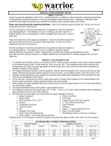
Front 2.2 Shocks
Rear 2.2 Shocks
Rr Track Bar Brckt
Rr Sway Bar Links
Rear Coils
Front Coil Springs
Rr Lwr Control Arms
KIT CONTENT
Fr Upr Control Arms
Rr Upr Control Arms
Rr Lwr Control Arms
Fr Adj Track Rod
Fr Sway Bar
Disconnects
Fr Brake Lines
Rr Brake Lines
Fr Trk Rod Brkt
Fr Spacer
Rear Spacer
Rear Shims (2)
Pitman Arm

FRONT INSTALLATION INSTRUCTIONS
1. Prior to installing this kit, with the vehicle on the ground, measure the heights of your vehicle. This measurement can
be recorded from the center of the wheel straight up to the top of the inner fender lip. Record the measurements.
LF:__________ ,RF:___________,
LR:__________, RR:___________
2. Place vehicle in park and chock the rear wheels. Raise the front of the vehicle with a jack and secure a jack stand
beneath each frame rail behind the front control arms. Ease the frame down onto the stands.
3. Remove the front tires/wheels, using a 19mm deep well socket.
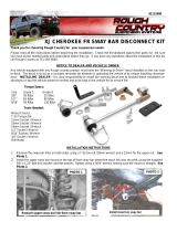
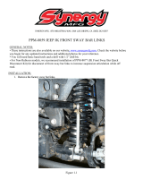
4. Using a 21mm socket, remove bolt securing the front track bar to the frame. Retain stock hardware. See Photo 1.
5. Using a 18mm socket and wrench remove the bottom sway bar bolts. Using a 21mm socket and 21mm wrench, re-
move the top of the sway bar link. Retain hardware for later use. See Photo 2.
6. Remove the lower shock bolt using a 18mm socket and
wrench. Using a 14mm wrench unbolt the top of the shock
and remove. See Photo 3. Retain the lower stock hard-
ware.
7. Using a 21mm socket and wrench loosen the upper and
lower control arm bolts at the axle and frame, but do not
remove.
8. On some models it will be necessary to remove the brake
line bracket from the frame to allow the coils to be re-
moved. Using a 10MM socket, remove the brake line
bracket from the stock location.
9. Push down on the axle to allow room for the coils to be re-
moved. Remove stock coil springs. Retain coil isolators.
10. Using a 21mm wrench, remove the bolts that secure the
lower link arms to the axle.
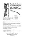
11. Remove the drive shaft from the differential using a 15mm wrench. See Photo 4.
12. Remove the driveshaft from the transfer case by removing the 8-8mm bolts as shown in Photo 5. Remove the shaft
from the Jeep. Driveshaft install will be performed in a later step.
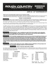
PHOTO 3
PHOTO 1 PHOTO 2
Remove the track rod from the frame Remove the front sway bar links
Remove the front shock absorbers
PHOTO 4 PHOTO 5

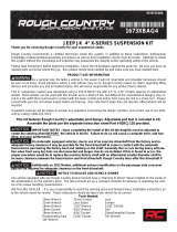
13. Adjust the lower control arms to a length of 22 7/8” from center of hole to center of hole and tighten the jam nut using
a 1 7/8” wrench. Install the adjustable heim end in the frame mount and the other end in the axle mount. Do not
tighten arms in the mounts at this time. See Photo 6. The bend on the lower control arm should be facing inward to
allow for the tires to achieve full lock to lock turning.
14. Remove the bolts securing the upper control arms to the axle using a 18mm wrench/socket. It will be necessary to
cut out the passenger side upper bolt as shown in Photo 7 to remove the control arm.
15. After the stock control arms have been removed assemble the bushings /sleeves in the upper control arms with the
heim joints. Adjust the arms to a length of 18 3/4” from center of hole to center of hole and tighten the jam nut using
a 1 1/8” wrench. Install in the heim joint in the upper mounts with supplied 12mm x 80mm bolt on the passenger side
frame and stock hardware on the driver side.
16. Install the opposite end on the axle with stock hardware. Do not fully tighten at this time. See Photo 8.
17. Loosen the stock brake line from the metal line on the frame rail shown in Photo 9 using a 12 mm line wrench. A
catch pan will be needed to catch the brake fluid.
18. Remove the line from the frame rail using a 10mm socket as shown in Photo 10. Remove the brake line from the
caliper and replace the brake line with the supplied stainless steel lines and brackets as shown in Photo 11.
Reattach at the caliper with new supplied crush washers, tighten line and install the spring clip.
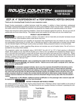
PHOTO 7
PHOTO 8 PHOTO 9
PHOTO 10 PHOTO 11
Cut passenger side upper bolt to remove
Install the new upper control arms Remove the steel line from the rubber line
Remove the brake bracket from the frame rail Install new brake line with bracket & clip
PHOTO 6
Install new lower control arms

19. Install the bushings and sleeves from 1681bag2 in the shock box into the RCX shock absorber Part # 660585. Po-
sition the cup washer and stem bushing on the stem end of the shock and insert the stem in the upper shock tower.
Install the remaining bushing and washer and loosely secure using the supplied nut. Tighten until the bushing swells
slightly using a 9/16” wrench. NOTE: The RC 2.2 Series shocks are built to run piston down and have a built in
bump stop thus a longer bump stop or bump stop extension is not needed with this kit.
20. Attach the lower end of the shock to the axle and secure using the stock hardware. Tighten to 80 ft/lbs.
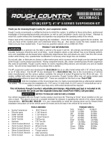
21. Remove the stock stabilizer and bracket from the axle mount using a 18mm wrench See Photo 12.
22. Install the track rod bracket as shown on the stock mount. Install the crush sleeve as shown in Photo 13.
23. Install the stock hardware in the bracket as shown. See Photo 14. Do not tighten at this time.
24. Install the supplied u-bolt and nuts in the bracket as shown in Photo 15. Do not tighten at this time
25. Install the two 3/8” x 1 1/4” bolts, washer and nuts in the new bracket and supplied stabilizer bracket if reusing the
stock stabilizer in the far left holes as shown. If not installing the stock stabilizer, the two 3/8” x 1 1/4” bolts will be
installed in the two far left holes in the bracket with out the supplied stabilizer bracket. See Photo 16.
26. Drill the rear mount using a 3/8” drill bit and install the 3/8” x 1 1/4” bolt, washer and flange lock nut. See Photo 17.
PHOTO 14
PHOTO 12 PHOTO 13
PHOTO 14 PHOTO 15
Remove the stabilizer from the axle Install crush sleeve and bracket
Install the stock hardware Install the supplied u-bolt
PHOTO 16 PHOTO 17
DRILL 3/8” HOLE
INSTALL HARDWARE

27. Tighten all 3/8” hardware using a 9/16” wrench.
28. This next two steps will be performed if the stock stabilizer is retained. On 07-10 Models mark the location on
the factory tie rod bracket on the tie rod and loosen the u-bolt nuts using a 13mm wrench. Slide the bracket down 1
1/4” rotate to position the stud up as shown and retighten tie rod end bracket. See Photo 18.
29. On 2011 models loosen the tie rod bracket using a 15mm wrench. Mark original location and move the bracket 1
1/2” and rotate the tie rod bracket as shown to allow full stroke of the stabilizer cylinder. See Photo 19.
30. Install the factory stabilizer in the new track rod / stabilizer mount with the body of the stabilizer on the axle mount
with stock hardware and tighten using a 18mm socket / wrench. See Photo 20.
31. Adjust the track bar to a length of 32 7/8” center of hole to center of hole. Install the new track bar into stock frame
bracket using the stock hardware.
32. Check to make sure the body is centered over the axle and install the stock track bar into the new track rod bracket
as shown in Photo 20 using the supplied 14mm x 80mm bolt, flat washers and lock nut. Tighten using a 21mm & 22
mm socket / wrench. Tighten jam nuts with a 18mm wrench. It may be necessary to turn the steering wheel to
align the track rod end with the axle.
33. On the front sway disconnects, assemble the supplied jam nut and end link on the sway bar link body. Adjust the
sway bar to approx 11” for a 4” & 6” kit measuring end to end. Tighten the end and jam nut using a 18mm wrench.
34. Install the new sway bar link on the factory sway bar as shown in Photo 21 with the supplied 12mm Flange lock nut
using a 16mm & 18mm wrench.
35. Install the new sway bar link on the sway bar bracket and swing up the assembly to the frame rail. See Photo 22.
Remove the sway bar link from the bracket while holding the bracket in place.
36. Mark the holes to be drilled and remove the bracket from the frame. See Photo 23.
Photo 21
Install upper end on sway bar
Photo 22
Position bracket to be drilled
Photo 23
Center punch holes
PHOTO 18
MOVE STABILIZER BRACKET
PHOTO 19
PHOTO 20
INSTALL STOCK ATABILIZER IN MOUNT

36. Drill the two holes per side using a 17/64” drill bit. See Photo 24. Be sure to only drill through outside of the frame.
37. Install the frame bracket with the supplied 5/16” self tapping bolts (2 per bracket) using a 1/2” wrench. SeePhoto 25.
38. Install the supplied mounting pin as shown in Photo 26 and tighten using 19mm socket / wrench.
39. Install the new Rough Country coil spring spacer as shown in Photo 27 in the factory location, making sure the coil
is positioned properly in the lower seat, as stock was.
40. Swing the new sway bar link down and secure on the
mounting pin using the supplied quick disconnect pin. See
Photo 28.
41. Using a 21mm socket remove the tie rod end from the
pitman arm. Remove the pitman arm nut using a 33mm
socket.
42. Using a pitman arm puller, remove factory pitman arm.
See Photo 29.
43. Install the new pitman arm with the stock hardware an
using a 33mm socket. See Photo 30. Reinstall the drag
link on the new pitman arm with the stock nut and using a
21mm wrench.
44. Reinstall the front tires/wheels, using a 19mm deep well
socket. Lower the vehicle to the floor.
Photo 25
Tighten 5/16” self tapping bolts
Photo 24
Drill Holes using a 17/64” drill bit
Install mounting pin on the axle
Photo 26 PHOTO 27
Link shown installed on pin
Photo 28
PHOTO 29 PHOTO 30

REAR INSTALLATION INSTRUCTIONS
1. Chock front wheels. Jack up the rear of the vehicle and support the vehicle with jack stands, so that the rear wheels
are off the ground. Position a jack so it supports, but does not raise the rear axle.
2. Remove the rear tires/wheels, using a 19mm deep well
socket.
3. Using a 21mm socket remove the track bar from the frame
on the passenger side. Using a 21mm socket remove the
track bar bolt at the axle and remove the track bar from the
vehicle. Retain the frame side stock hardware for reuse.
4. Using a 21mm socket loosen, but do not remove the bolts
securing the lower control arms at both the axle and frame.
5. On the rear of the vehicle remove the factory sway bar link
using a 18mm socket and wrench on the lower. Remove
the upper hardware using a 18mm wrench and a 19mm
wrench on the ball joint end.
6. Using a 10mm wrench, unbolt the brake hose bracket at
the frame. Retain hardware for later use.
7. Remove and discard the rear shocks using a 18mm
wrench. Retain stock hardware.
8. Lower the axle enough to remove the stock coil springs.
9. Remove the upper control arms from the frame and axle using a 18mm wrench. Retain the upper flag nut in the
frame and all other factory hardware. See Photo 31.
10. Assemble the heim joints in the upper control arms The rear upper heim joint is labeled as “Rear Upper” on the
heim joint. Adjust to a length of 18 3/4” from center of hole to center of hole and tighten the jam nut using a 1 1/8”
wrench. Install in the heim end on the frame with stock flag nut and the lower on the axle with factory hardware using
a 18mm wrench. See Photo 32. Photo 33 showing rear axle install. Do not fully tighten at this time.
11. Using a 21mm socket remove the bolts securing the lower control arms at both the axle and frame. Passenger side
lower shown in Photo 34. Remove the control arms and retain the hardware for reuse.
12. Adjust the new lower control arms to a length of 20 1/2” from center of hole to center of hole and tighten the jam nut
using a 1 7/8” wrench. Install the hiem on the frame and the opposite end on the axle with the factory hardware us-
ing a 21mm wrench. See Photo 35. Do not fully tighten at this time.
PHOTO 31
PHOTO 32 PHOTO 33
PHOTO 34 PHOTO 35
Remove the upper control arms
Install the new upper control arms on frame Install the new upper arm on the axle
Remove the lower control arms Install the lower control arms

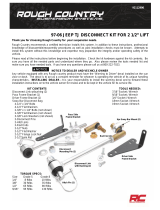
13. Install the new coil spring spacer with supplied washer/nut retainer and secure the assembly with supplied 1/2” x 2
3/4” bolt & lock washers through the factory coil mount as shown in Photo 36 & 37.
14. Install the factory coil spring isolator as shown. See Photo 38.
15. Install the supplied rear coil shim as shown in Photo 39.
16. Install the top of the coil back onto the coil seat. When installing the bottom of the coil into the seat rotate the coil
until the pigtail hits the spring stop. Lower vehicle slightly, watching coils to assure they properly seat on top
17. Place the bracket on the factory mount and install the supplied 3/8” x 1” Bolts , washers and Flange lock nuts as
shown in the factory holes. Do not tighten at this time. See Photo 40.
18. Verify the original track bar mounting hole and the hole in the track bar bracket are aligned vertically. Using the track
bar bracket as a template mark and drill a 13/32” hole in the top of the original track bar mount from the top.
19. Install using the .375-16 x 1” bolt, washer through the drilled hole from the top and secure with flange nut using a
9/16” wrench and socket. Do not tighten at this time. See PHOTO 41.
Photo 36 Photo 37
Photo 38 PHOTO 39
PHOTO 40 PHOTO 41
Install the rear
track rod
bracket on the
axle
Install the 3/8” x 1” bolt in bracket

20. Insert the supplied sleeve, inside the factory track bar mount. Insert the supplied 14mm” x 80mm” bolt through the
bracket, factory mount, and sleeve secure using the washer and nut. Do not fully tighten. See Photo 42.
21. Tighten all track rod bracket hardware including 14mm x 80mm bolt and 3/8” bolts.
22. Install the factory track bar with the supplied 14mm x 75mm bolt washer & flange nut (upper hole) with the head of
the bolt on the front by the coil spring. See Photo 43. The passenger side mount on the track bar will be installed in
a later step.
23. Locate the 4 sway bar link sleeves. Insert the supplied 1/2” inner diameter sleeves into the sway bar link bushings.
Using the supplied .500-16 x 2.75” bolts, washers and nuts from 1681bag, install the sway bar links to the sway bar,
and axle mount., and tighten using a 13/16” socket and 7/8” wrench. See PHOTO 44. Make sure the bolts are in-
stalled with the head of the bolt toward the tire as shown.
24. Install the supplied bushings and sleeves from 1681Shock bag2 to part # 660586 rear shocks. Install the RCX 2.2
series shocks using the factory hardware, using a 18mm socket for the top, and a 18mm socket for the bottom. Shaft
end of the shock will be pointed down. The shocks have a built in bump stop. A longer bump stop will not be needed.
See PHOTO 45.
25. Remove the rubber brake line from the steel line using a 12mm wrench as shown in Photo 46 and remove the brake
line from the caliper using a 15mm wrench.
26. Install the new brake line bracket using a 10mm wrench
and stock hardware to secure to factory location. Install the
new brake line on the hard line and tighten. Install spring
clip as shown in Photo 47. Install on the caliper with sup-
plied crush washers, using a 15mm wrench.
27. Reinstall the rear tires/wheels, using a 19mm deep well
socket
28. Lower the vehicle to the floor.
29. Using a 21mm socket tighten the front and rear lower con-
trol arms, both ends to 130 ft.lbs.
30. Using a 18mm socket tighten the front upper control arms,
both ends to 80 ft.lbs
31. Using a 21mm socket tighten the rear upper control arms to
130 ft. lbs.
32. Make sure the body is centered over the rear axle and install the rear track rod bracket in the factory location on the
frame with the factory hardware and using a 21mm wrench.
PHOTO 43
Install washers on head of bolt
PHOTO 44 PHOTO 45
Install the RCX 2.2 Shock Absorbers Remove the rear brake lines
PHOTO 46
Install the new brake lines
PHOTO 42
Bolt shown pointed toward rear of vehicle

31. Adjust front draglink to center the steering wheel before driving by loosening the two bolts and turning the adjust-
ment collar. See PHOTO 48 & 49.
IMPORTANT NOTE : The draglink must be adjusted to the center steering wheel BEFORE the vehicle is driven.
Failure to do so will cause a computer error, odd handling, and poor performance.
POST INSTALLATION
1. Confirm that the draglink was adjusted to the center steering wheel BEFORE the vehicle is driven. Failure to do
so will cause a computer error, odd handling, and poor performance.
2. Check all fasteners for proper torque. Check to ensure there is adequate clearance between all rotating, mobile,
fixed and heated members. Check steering for interference and proper working order. Test brake system.
3. Perform steering sweep. The distance between the tire sidewall and the brake hose must be checked closely. Cycle
the steering from full turn to full turn to check for clearance. Failure to perform inspections may result in component
failure.
4. Re-torque all fasteners after 500 miles and recheck after 1000 miles. Alignment must be checked by a qualified me-
chanic. Visually inspect components and re-torque fasteners during routine vehicle service.
5. Readjust headlights to proper settings.
6. Have a qualified alignment center realign the front end, to the factory specifications immediately.
Caster preferred 4.6 degree range +,- 1 degree
Camber preferred –0.25 degree range +,- 0.63 degree
Toe-in preferred 0.15degree range +,- 0.15 degree
MAINTENANCE INFORMATION
It is the ultimate buyers responsibility to have all bolts/nuts checked for tightness after the first 500 miles and then every
1000 miles. Wheel alignment steering system, suspension and driveline systems must be inspected by a qualified pro-
fessional mechanic at least every 3000 miles.
PHOTO 48 PHOTO 49
Loosen adjustment collar Adjust as necessary
Thank you for purchasing a Rough Country Suspension System.
By purchasing any item sold by Rough Country, LLC, the buyer expressly warrants that he/she is in compliance with all
applicable , State, and Local laws and regulations regarding the purchase, ownership, and use of the
item. It shall be the buyers responsibility to comply with all Federal, State and Local laws governing
the sales of any items listed, illustrated or sold. The buyer expressly agrees to indemnify and hold
harmless Rough Country, LLC for all claims resulting directly or indirectly from the purchase, owner-
ship, or use of the items.
/