Page is loading ...

FORM#40051.01-07162019 PRINTED IN U.S.A. PAGE 1 OF 13
2019 JEEP GLADIATOR JT
2.5” Inch Leveling Kit
INSTALLATION INSTRUCTIONS
MAKE SURE YOU HAVE THE CORRECT LIFT FOR YOUR VEHICLE:
Double check the Year, Make, Model, Lift Height and KIT Part Numbers.
Engineered for 2019+ Jeep Gladiator JT
4WD 4-Door Models
Includes Sport, Sport S, Overland & Rubicon
Prior to beginning the installation, OPEN the Boxes and CHECK the Included Components
Compared to the Parts Breakdown. Check all parts and hardware in the box with the parts list below. Be sure you
have all needed parts and know where they install.
IF you find a packaging error, contact SUPERLIFT directly. Do not contact the dealer where the system was
originally purchased. You will need the control number from each box when calling; this number is located at
the bottom of the part number label and to the right of the bar code.

FORM#40051.01-07162019 PRINTED IN U.S.A. PAGE 2 OF 13
How to Read the Kit Breakdown Charts:
The ‘K KIT BREAKDOWN’ lists the Part Numbers, Quantities & Part Description of the Boxes that are included in the K KIT.
The ‘KIT BREAKDOWN’ lists Part Numbers, Quantities & Part Description of the Individual Components & Hardware Bags
that are included in Each Box. The ‘HARDWARE BREAKDOWN’ lists the Part Numbers, Quantities & Part Description of the
Individual Components.
Kit Part Number 40051
Part Number Qty. Part Description
55-26-5825 2 Coil Spacer, Front
55-13-5825 2 Shock Spacer, Front
55-19-5825 2 Sway Bar Link, Front
77-40051 1 Hardware Bag, Bushings and Sleeves
77-40051A 1 Hardware Bag, Nut and Bolts
Kit Part Number 77-40051A
Part Number Qty. Part Description
01-60418 4 Bushing, Hourglass
24-5704 6 Sleeve, 0.75" OD x 0.50" ID x 1.50" Long
55-08-5800 2 Tab Nut
Kit Part Number 77-40051
Part Number Qty. Part Description
12C5NN 2 1/2" Nut, Nyloc Coarse Thread
12MFW 4 12mm Flat Washer
12MNN 2 12mm Nut, Nyloc Coarse Thread
12MX1.75X80CS 2 12mm x 80mm Bolt, 1.75 Coarse Thread
12SW 2 1/2" Washer, SAE
12X314C8CS 4 1/2" x 3-1/4" Bolt, Coarse Thread
38C5FN 2 3/8" Flange Nut, Coarse Thread
38SW 2 3/8" Washer, SAE
38X114C8CS 2 3/8" x 1-1/4" Bolt, Coarse Thread
38X3C8CS 2 3/8" x 3" Bolt, Coarse Thread
K KIT BREAKDOWN
HARDWARE BAG BREAKDOWN
Step Part Number Qty.
Per Kit Description New Attaching Hardware Qty. Per
Bracket
Hardware Bag
Number
12 55-26-5825 2 Coil Spacer, Front 3/8" x 1-3/4" Bolt, Coarse Thread 1
3/8" Washer, SAE 1
3/8" Tab Nut 1
13 55-13-5825 2 Shock Spacer, Front 24-5704 Sleeve, 0.75" OD x 0.50" ID x 1.50" Long 1 77-40051
3/8" x 1-14" Bolt, Coarse Thread 1 77-40051A
1/2" x 3-1/2" Bolt, Coarse Thread 1
1/2" Washer, SAE 2
3/8" Flange Nut, Coarse Thread 1
1/2" Nut, Nyloc Coarse Thread 1
3/8" Washer, SAE 1
21 55-19-5825 2 Sway Bar Link, Front 01-60418 - Bushing, Hourglass 2 77-40051
24-5704 - Sleeve, 0.75" OD x 0.50" ID x 1.50" Long 2 77-40051A
12mm x 80mm Bolt, 1.75 Coarse Thread 1
12mm Flat Washer 2
12mm Nut, Nyloc Coarse Thread 1
77-40051

FORM#40051.01-07162019 PRINTED IN U.S.A. PAGE 3 OF 13
Read And Understand All Instructions And Warnings Prior
To Installation Of System AND Operation Of Vehicle.
INTRODUCTION BEFORE INSTALLATION...
Installation requires a professional mechanic. In addition to these instructions, professional knowledge of
disassembly / reassembly procedures and post installation checks must be known.
PRIOR to beginning, inspect the vehicles steering, driveline, and brake systems, paying close attention to the
suspension link arms and bushings, sway bars and bushings, tie rod ends, pitman arm, idler arm, ball joints
and wheel bearings. Also check the steering sector-to-frame and all suspension-to-frame attaching points for
stress cracks. The overall vehicle must be in excellent working condition; repair or replace all worn parts.
Read instructions several times before starting.
Read each step completely as you go.
Be sure you have all needed parts and know where they install.
• Front end alignment is necessary.
• A foot-pound torque reading is given in parenthesis ( ) after each appropriate fastener.
• Tool and Wrench/Socket size is given in brackets { } after each appropriate step.
• Always wear safety glasses when using power tools.
• Prior to attaching components, be sure all mating surfaces are free of grit, grease, excessive undercoating, etc.
• Do not fabricate any components to gain additional suspension height.
• A factory service manual should be on hand for reference.
• Due to payload options and initial ride height variances, the amount of lift is a ‘base figure’. Final ride height
dimensions may vary in accordance to original vehicle stance.
BEFORE YOU DRIVE...
Check all fasteners for proper torque. Check to ensure for adequate clearance between all rotating, mobile,
fixed, and heated members. Verify clearance between exhaust and brake lines, fuel lines, fuel tank, floor
boards and wiring harness. Check steering components for clearance.
Test and inspect brake system. Perform steering sweep to ensure front brake hoses have adequate slack
and do not contact any rotating, mobile or heated members. Inspect rear brake hoses at full extension for
adequate slack. Failure to perform hose check/replacement may result in component failure.
Perform head light check and adjustment.
It is the ultimate buyer’s responsibility to have all bolts / nuts checked for tightness after the
first 100 miles and then every 1000 miles. The steering, suspension and driveline systems, plus wheel alignment
should be inspected by a qualified professional mechanic at least every 3000 miles.
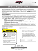
TIRES & WHEELS...
Larger rim and tire combinations may increase leverage
on suspension, steering, and related components. When
selecting combinations larger than OE, consider the
additional stress you could be inducing on the OE and
related components.
Stock 17” and 18” Wheels Will Fit back on the
vehicle once this suspension system is installed.
ANY larger or wider tire & wheel
combination other than listed Will Require Vehicle
Trimming.
Tire Size Wheel Backspacing
(INCH) Offset (MM)
35x12.50R17 17x9 4.00-4.75 -
315/70R17 17x9 4.00-4.75 -
35x12.50R18 18x9 4.00-4.75 -
325/65R18 18x9 4.00-4.75 -
35x12.50R20 20x9 4.00-4.75 -
315/60R20 20x9 4.00-4.75 -
Maximum BS/Offset Listed
TIRE SIZE SPECIFICATIONS

FORM#40051.01-07162019 PRINTED IN U.S.A. PAGE 4 OF 13
ALL Tire & Wheel Combinations Should Be Test Fit Prior to Installation. * Some Minor
Trimming Maybe Required. Some minor trimming will be required with certain wheel/tire combinations.
This is normal with most aftermarket tire/wheel fitments. As a rule of thumb, deeper backspacing and
shorter/narrower tires will reduce/eliminate trimming required.
IMPORTANT DISCLAIMER: The provided tire/wheel fitments are approximate. Actual dimensions of a given
tire size can vary considerably from one brand to another. Manufacturers’ wheel offset and backspacing
measurement points are not always consistent. Backspacing greatly impacts tire-to-fender clearance when
turning. Wheel width and backspacing influence whether the tires protrude past the fenders, and to what
extent. Considering these important factors, we recommend that you fit-check your tire/wheel selection prior
to purchasing.The provided tire/wheel fitments are approximate. Actual dimensions of a given tire size can
vary considerably from one brand to another. Manufacturers’ wheel offset and backspacing measurement
points are not always consistent. Backspacing greatly impacts tire-to-fender clearance when turning.
Wheel width and backspacing influence whether the tires protrude past the fenders, and to what extent.
Considering these important factors, we recommend that you fit-check your tire/wheel selection prior to
purchasing.
TOOLS & TECH...
The chart is a listing of the main tools need to
install this lift kit system.
We have also included a Tech Tip noted by this
icon to help if we have found a
quicker or easier way to accomplish a task in the
steps.
Floor Jacks Standard Metric
Jack Stands 9/16" 8mm
Adjustable Pliers 3/4" 13mm
Torque Wrench 15mm
18mm
21mm
22mm
Tie Rod Puller Tool 6mm Allen
Plastic Fastener Removal Tool
Tools
Miscellaneous Tools Wrench / Socket Sizes
Flathead Screwdriver
Ball Peen Hammer
Size Grade 5 Grade 8 Size Grade 8.8 Grade 10.9
5/16" 15 ft/lbs. 20 ft/lbs. 6mm 5 ft/lbs. 9 ft/lbs.
3/8" 30 ft/lbs. 35 ft/lbs. 8mm 18 ft/lbs. 23 ft/lbs.
7/16" 45 ft/lbs. 60 ft/lbs. 10mm 32 ft/lbs. 45 ft/lbs.
1/2" 65 ft/lbs. 90 ft/lbs. 12mm 55 ft/lbs. 75 ft/lbs.
9/16" 95 ft/lbs. 130 ft/lbs. 14mm 85 ft/lbs. 12 ft/lbs.
5/8" 135 ft/lbs. 175 ft/lbs. 16mm 130 ft/lbs. 165 ft/lbs.
3/4" 185 ft/lbs. 280 ft/lbs. 18mm 170 ft/lbs. 240 ft/lbs.
Torque Specifications
STANDARD METRIC

FORM#40051.01-07162019 PRINTED IN U.S.A. PAGE 5 OF 13
Use the check-off box
found at each step to help you keep your place. Two
denotes that
one check-off box is for the Driver Side (Left) and one is for the Passenger Side (Right). Unless otherwise
noted, always start with the Driver Side.
FRONT DISASSEMBLY
Save ALL factory components and hardware for reuse, unless noted.
As you unstall OEM parts, Place the Factory Hardware Back into the Factory Location. This will
save you time and make the install easier to complete.
1. PREPARE VEHICLE FOR FRONT...
Disconnect the battery.
Chock rear tires and place transmission in neutral.
Raise the front of vehicle with a jack and secure a jack
stand beneath each frame rail. Ease the frame down onto
the stands, place transmission in Low Gear for Manual
Transmission or Park for Automatic. Remove the front
wheels & tires. [Lug Nuts 22mm Deep Well Socket]
2. REMOVE SWAY BAR LINKS...
[Illustration 1] Remove the factory hardware from the
lower sway bar link mount at the axle mount. [Bolt: 18mm,
Nut: 18mm] Retain factory hardware.
[Illustration 1] Remove the factory hardware from
the upper sway bar link at the sway bar. [6mm Allen and an
18mm wrench]
3. DISCONNECT DRAGLINK FROM PITMAN ARM...
[Illustration 2] Loosen, but
do not remove the factory
nut from the draglink where
it attaches to the pitman arm.
[21mm] TECH TIP: Rotate the
sway bar upward or downward
as needed.
Using a tie rod puller tool,
separate the draglink from the
pitman arm. Be careful. Do not
let the draglink fall abruptly. It
could cause damage.
If you do not have a puller, you
can use the method of striking the pitman arm near the
draglink to dislodge the draglink. Strike the pitman arm
portion only.
Remove the draglink nut and save for re-install.
4. DISCONNECT TRACK BAR AT AXLE MOUNT...
[Illustration 3] Remove the factory bolt and tab nut
from the track bar at the lower axle mount. [21mm]
Retain the factory hardware.
Illustration 1
Illustration 2
Illustration 3

FORM#40051.01-07162019 PRINTED IN U.S.A. PAGE 6 OF 13
5. RUBICONS: DISCONNECT FRONT LOCKER...
[Illustration 4] RUBICON Models: The front locker must be
disconnected so the wiring connectors are not over-extended.
On the Driver Side located on the ‘inner’ frame rail above the axle,
Unplug the harness plug. Unclip the wiring harness clips from the
frame. [Plastic Fastener Removal Tool]
6. UNCLIP CENTER AXLE DISCONNECT (CAD)...
[Illustration 5] The Center Axle Disconnect or otherwise known as
the CAD, must be disconnected so the wiring connectors are not over-
extended.
On the Passenger Side located on the ‘inner’ frame rail above the axle,
remove the zip tie from the wiring harness. Unclip the wiring harness
clips from the frame. [Plastic Fastener Removal Tool]
At the Passenger Side axle, unplug the CAD harness. Unclip wiring clips from front axle. [Plastic Fastener
Removal Tool] Make sure there is adequate slack on all wires.
7. REMOVE BRAKE LINE BRACKET...
[Illustration 6] On the Driver Side & Passenger Side, remove the brake line bracket from the lower
control arm. [15mm]
8. DISCONNECT FRONT DRIVESHAFT...
[Illustration 7] Make an alignment mark on the front driveshaft and front differential input yoke.
Remove the four bolts from the yoke. [15mm] Save the driveshaft hardware.
Remove the front driveshaft from the differential. Secure the driveshaft safely up and out of the way with a
bungee, mechanic’s wire or other method.
Illustration 4
Illustration 5
Illustration 7Illustration 6

FORM#40051.01-07162019 PRINTED IN U.S.A. PAGE 7 OF 13
9. DISCONNECT FRONT AXLE VENT TUBE...
[Illustration 8] Locate the brake line bracket attached on the Driver Side frame to the rear of the shock
tower. [Plastic Fastener Removal Tool] Unclip the axle vent hose clip from the brake line bracket. Follow the
vent tube up and unclip the frame attachment. [Plastic Fastener Removal Tool] Continue to follow the vent
tube up and unclip from the shock tower that is behind the wheel well plastic. [Plastic Fastener Removal Tool]
10. REMOVE FRONT SHOCKS...
[Illustration 9]
If you are installing the Shock
Spacer Kit, you ONLY need to
disconnect the lower shock
mount.
Disconnect the shock from
the upper shock tower mount.
[18mm socket]
Disconnect the shock from the
lower mount at the axle. [18mm
wrench \ 18mm socket]
Remove shocks. Retain the shocks and shock mount hardware.
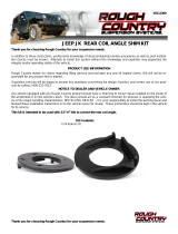
11. REMOVE FRONT COIL SPRINGS...
[Illustration 10] Lower the axle enough to facilitate removing the front coil
springs. Remove the coil springs. Remove the lower coil spring mount pad.
FRONT ASSEMBLY
12. INSTALL FRONT SPRING SPACERS & COIL SPRINGS...
[Illustration 11] Locate the (2) SUPERLIFT coil spring spacer brackets, (#55-
26-5825). These brackets are not side specific.
Locate Hardware Bag #77-5803. Hardware PER Side: (1) 3/8” x 3” Bolt, Coarse
Thread, (1) 3/8” SAE Washer & (1) #55-08-5800 - 3/8” Nut, Tab
Locate the lower coil spring mount pad. Install the pad over the spring spacer.
Insert the 3/8” washer onto the 3” bolt. Insert the bolt through the spring mount pad and into the top of the
#55-26-5825 spacer bracket. Place the spacer onto the axle housing. Align the 3“ bolt into the axle mount hole.
Reach under the spring mount pad and above the axle tube to start the #55-08-5800 - 3/8” tab nut onto the spacer
bracket bolt. Tighten the lower spring mount pad & coil spring spacer bracket into place. [9/16” socket] (25)
Illustration 8
Illustration 9
Illustration 10

FORM#40051.01-07162019 PRINTED IN U.S.A. PAGE 8 OF 13
On the Passenger Side, it may be necessary to remove the ABS bracket to install the tab nut. At
the rear of the axle above the shock mount, disconnect factory brake line bracket from axle coil spring seat.
[10mm] Pull bracket rearward to allow clearance. Do not over extend brake lines or ABS lines.
Once spring spacer is tight, reinstall ABS line mounting bracket onto axle. [10mm]
Insert the coil spring into the upper tower first. Be sure that the coils are indexed so they seat properly then
raise the axle enough to hold the coil springs in place.
13. INSTALL FRONT SHOCK SPACER INSTALL...
[Illustration 12] Locate the (2) SUPERLIFT front shock spacers (#55-13-5825). They are not side specific.
Locate Hardware Bag #77-5800. Hardware PER Side: (1) #24-5704 Sleeve, 0.75” OD x 0.50” ID x 1.50” Long, (1)
3/8” x 1-1/4” Bolt, Coarse Thread, (1) 3/8” SAE Washer, (1) 3/8” Flange Nut, Coarse Thread (1) 1/2” x 3-1/4” Bolt,
Coarse Thread, (1) 1/2” SAE Washer & (1) 1/2” Nyloc Nut, Coarse Thread.
Swing the shock rearward and up out of the way. Place the SUPERLIFT front shock spacer on the factory shock
mount with pointing rearward and up. Insert the 3/8” SAE washer onto the 3/8” x 1-1/4” bolt. Insert the bolt/
washer up though the bottom hole of the bracket/factory mount. Install 3/8” flange nut. [9/16 wrench / 9/16
socket]
The bottom hole of the factory shock mount may have to be deburred before the bolt is
installed easily. Use a 3/8” drill bit to deburr the hole if needed.
Attach 1/2” SAE Washer onto the 1/2” x 3-1/4” bolt. Insert the bolt pointing inward into the shock spacer/
factory shock mount. Attach #24-5704 sleeve. Continue bolt through spacer/shock mount, then attach 1/2”
SAE washer & 1/2” Nyloc nut. Snug tighten only. [3/4” wrench / 3/4” socket]
Swing factory shock into place and align with the upper hole of the spacer. Install shock with factory
hardware with the bolt pointing inward. Snug tighten only. [18mm wrench \ 18mm socket]
Shocks will be tightened completely when the vehicle is set on the ground.
Illustration 12
Illustration 11

FORM#40051.01-07162019 PRINTED IN U.S.A. PAGE 9 OF 13
14. REATTACH BRAKE LINE BRACKET...
[Illustration 13] On the Driver Side & Passenger Side, reattach the brake line bracket to the lower control
arm. [15mm]
15. REATTACH FRONT AXLE VENT TUBE...
[Illustration 14] Locate the brake line bracket attached on the Driver Side frame to the rear of the shock
tower. Re-clip the axle vent hose clip to the brake line bracket. Follow the vent tube up and re-clip to the
frame attachment. Continue to follow the vent tube up and re-clip to hole on the shock tower.
16.
REATTACH FRONT DRIVESHAFT...
[Illustration 15] Locate the front driveshaft factory bolts. Apply thread locking compound to the
factory bolt threads before installation. Align mark on the front driveshaft and front differential input yoke,
reconnect the front driveshaft to the front differential. [15mm] (81)
With the bolts in place, use a pry bar to keep the driveshaft from turning while you tighten &
torque into place.
17. RUBICONS: RECONNECT FRONT LOCKER...
[Illustration 16] RUBICON Models: On the Driver Side located on the ‘inner’ frame rail above the axle, re-
clip the plug wiring harness together & re-clip back to the frame. Reconnect so the wiring connectors are not
over-extended.
Illustration 13 Illustration 14
Illustration 15 Illustration 16

FORM#40051.01-07162019 PRINTED IN U.S.A. PAGE 10 OF 13
18. RECLIP CENTER AXLE DISCONNECT (CAD)...
[Illustration 17] At the Passenger Side axle, re-plug the CAD harness.
On the Passenger Side on the ‘inner’ frame rail above the axle, re-clip the plug wiring harness together & re-
clip back to the frame. Reconnect so the wiring connectors are not over-extended.
19. REATTACH TRACK BAR AT AXLE MOUNT...
[Illustration 18] Using the factory bolt and tab nut, reattach the track bar at the lower axle mount. [21mm]
A rachet strap will help position the track bar. Attach the rachet strap to the track bar upper
frame mount & to the lower axle mount. Racket the strap to align the track bar with the mount hole.
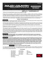
20. INSTALL FRONT SWAY BAR LINKS...
[Illustration 19] Locate the (2) SUPERLIFT front sway bar links (#55-16-5825). These
supplied front sway bar links are shorter than the supplied rear sway bar links.
Locate Hardware Bag #77-5801 & #77-5801A. Hardware PER Side: (2) 01-60418 - Bushing, Hourglass, (2) #24-
5704 - Sleeve, 0.75” OD x 0.50” ID x 1.50” Long, (1) 12mm x 80mm Bolt, Coarse Thread, (2) 12mm Washer & (1)
12mm Nut, Nyloc Coarse Thread.
Lightly grease and install/press the hourglass shaped bushing and 0.50” ID sleeve into each end of the sway
bar link end.
Use the factory hardware to attach the lower sway bar link mount at the axle mount. [Bolt: 18mm, Nut:
18mm]
Attach 12mm Washer onto the 12mm x 80mm bolt. Insert the bolt pointing inward into the new sway bar
link. Continue bolt through sway bar, then attach 12mm washer & 12mm Nyloc nut. Snug tighten only.
[19mm wrench / 19mm socket]
Illustration 18
Illustration 17

FORM#40051.01-07162019 PRINTED IN U.S.A. PAGE 11 OF 13
21. FRONT TIRES / WHEELS...
[Illustration 20] Install the front tires & wheels. [Lug Nuts 22mm]
(140) Lower the vehicle to the ground.
When the tires / wheels are installed, always check for
and remove any corrosion, dirt, or foreign material on the wheel
mounting surface, or anything that contacts the wheel mounting surface
(hub, rotor, etc.). Installing wheels without the proper metal-to-metal
contact at the wheel mounting surfaces can cause the lug nuts to loosen
and the wheel to come off while the vehicle is in motion.
Reconnect the battery.
22. INITIAL FRONT CLEARANCE CHECK...
With the vehicle on the ground, cycle the steering lock-to-lock and
check all components for proper operation and clearances. Pay special
attention to the clearance between the tires / wheels and control arms,
brake hoses, ABS wiring, etc.
Raise the vehicle back onto jack stands and secure as per Step 1. With
the suspension ‘hanging’ at full extension travel, cycle the steering lock-
to-lock and check all components for proper operation and clearances. Pay special attention to the clearance
between the tires / wheels and control arms, brake hoses, ABS wiring, driveshaft-to-crossmember, etc.
Lower vehicle to the floor. Final tightening and adjustments to the front suspension installation will take
place once rear lift is completed.
23. CLEARANCE CHECK...
Check all hardware for proper torque specifications.
With the vehicle on the ground, check all components for proper operation and clearances. Pay special attention
to the clearance between the tires / wheels, brake hoses, wiring, etc. Check tire/wheel clearance with the
fenders/bumper as well as with the steering knuckle.
24. WHEEL ALIGNMENT...
Realign vehicle to factory OEM specifications. It is necessary to have a proper and professional wheel
alignment performed by a certified alignment technician. Align the vehicle to factory specifications. It is
recommended that your vehicle alignment be checked after any off-road driving.
25. HEADLIGHTS...
Re-adjust headlights to proper setting. In addition to your vehicle alignment, for your safety and others, it
is necessary to check and adjust your vehicle head lamps for proper aim and alignment.
Illustration 19
Illustration 20

FORM#40051.01-07162019 PRINTED IN U.S.A. PAGE 12 OF 13
26. FOUR WHEEL DRIVE…
Activate the four wheel drive system and check for proper engagement.
27. SUPERLIFT WARNING DECAL...
Install the WARNING TO DRIVER decal on the inside of the windshield, or on the dash, within Driver’s view.
IMPORTANT MAINTENANCE INFORMATION
It is the ultimate buyer’s responsibility to have all bolts / nuts checked for tightness after the
first 100 miles and then every 1000 miles. The steering, suspension and driveline systems, plus wheel alignment
should be inspected by a qualified professional mechanic at least every 3000 miles.
LIMITED LIFETIME WARRANTY / WARNINGS
Your SUPERLIFT® product is covered by the Limited Warranty explained below that gives you specific legal
rights. This limited warranty is the only warranty SUPERLIFT® makes in connection with your product purchase.
SUPERLIFT® neither assumes nor authorizes any retailer or other person or entity to assume for it any other
obligation or liability in connection with this product or limited warranty.
SUPERLIFT, LLC, LIMITED LIFETIME WARRANTY
What is covered? Subject to the terms below, SUPERLIFT® will repair or replace its products found defective
in materials or workmanship for so long as the original purchaser owns the vehicle on which the product
was originally installed. Your warranter is SUPERLIFT, LLC, doing business as SUPERLIFT® Suspension Systems
(“SUPERLIFT®”).
What is not covered? Your SUPERLIFT® Limited Warranty does not cover products SUPERLIFT® determines to
have been damaged by or subjected to:
• Alteration, modification or failure to maintain.
• Normal wear and tear (bushings, rod ends, etc.). Scratches or defects in product finishes
(powder coating, plating, etc.).
• Damage to, or resulting from, the vehicle’s electronic stability system, related components or
other vehicle systems.
• Racing or other vehicle competitions or contests. Accidents, impact by rocks, trees, obstacles or
other aspects of the environment.
• Theft, vandalism or other intentional damage.
Remedy Limited to Repair or Replacement. The exclusive remedy provided hereunder shall, upon SUPERLIFT’s
inspection and at SUPERLIFT’s option, be either repair or replacement of the product covered under this Limited
Warranty. Customers requesting warranty consideration should contact SUPERLIFT® by phone (1-800-551-4955)
to obtain a Returned Goods Authorization number. All removal, shipping and installation costs are customer’s
responsibility.
If a replacement part is needed before the SUPERLIFT® part in question can be returned, you must first purchase
the replacement part. Then, if the part in question is deemed warrant-able, you will be credited / refunded.
OTHER LIMITATIONS EXCLUSION OF DAMAGES YOUR RIGHTS UNDER STATE LAW
• Neither SUPERLIFT® nor your independent SUPERLIFT® dealer are responsible for any time loss, rental
costs, or for any incidental, consequential or other damages you may have.
• This Limited Warranty gives you specific rights, and this is the only warranty SUPERLIFT® makes in
connection with your product purchase. You may also have other rights that vary from state to state.
For example, while all implied warranties are disclaimed herein, any implied warranty required by law
is limited to the terms of our Limited Lifetime Warranty as described above. Some states do not allow
limitations of how long an implied warranty lasts and / or do not allow the exclusion or limitation of
incidental or consequential damages, so the limitations and exclusions herein may not apply to you.
SUPERLIFT® neither assumes nor authorizes any retailer or other person or entity to assume for it any
other obligation or liability in connection with this product or Limited Warranty.

FORM#40051.01-07162019 PRINTED IN U.S.A. PAGE 13 OF 13
IMPORTANT PRODUCT USE AND SAFETY INFORMATION / WARNINGS
As a general rule, the taller a vehicle is, the easier it will roll over. Offset, as much as possible,
what is lost in rollover resistance by increasing tire track width. In other words, go “wide” as you go “tall”; always
use as wide a tire and wheel combination as feasible to enhance vehicle stability. We strongly recommend,
because of rollover possibility, that the vehicle be equipped with a functional roll bar and cage system. Seat
belts and shoulder harnesses should be worn at all times. Avoid situations where a side rollover may occur.
Generally, braking performance and capabilities are decreased when significantly larger / heavier tires and
wheels are used. Take this into consideration while driving. Also, changing axle gear ratios or using tires that
are taller or shorter than factory height will cause an erroneous speedometer reading. On vehicles equipped
with an electronic speedometer, the speed signal impacts other important functions as well. Speedometer
recalibration for both mechanical and electronic types is highly recommended.
Do not add, alter, or fabricate any factory or aftermarket parts to increase vehicle height over the intended
height of the SUPERLIFT® product purchased. Mixing component brands is not recommended.
WE WANT TO SEE YOUR RIDE...
Grab photos of your SUPERLIFT Equipped truck in various poses and in action.
Email pictures to us at [email protected]
Tag us on Facebook: @superlift suspension systems
Tag us on Instagram: #superlift, #superliftsuspension, #superliftequipped
THANKS For Choosing SUPERLIFT...
For questions, technical support and warranty issues relating to this SUPERLIFT products, please contact
SUPERLIFT directly.
SUPERLIFT SUSPENSION
300 Huey Lenard Loop Rd.
West Monroe, Louisiana 71292
Phone: (318) 397-3000
Sales / Tech: (800) 551-4955
Fax: (318) 397-3040
SUPERLIFT.COM
/