Page is loading ...

97-06 JEEP TJ 4” SUSPENSION KIT
92190600
Thank you for choosing Rough Country for your suspension needs.
Rough Country recommends a certified technician installs this system. In addition to these instructions, professional
knowledge of disassemble/reassembly procedures as well as post installation checks must be known. Attempts to
install this system without this knowledge and expertise may jeopardize the integrity and/or operating safety of the
vehicle.
Please read all the instructions before beginning the installation. Check the kit hardware against the parts list. Be
sure you have all the needed parts and understand where they go. Also please review the tools needed list and
make sure you have needed tools.
PRODUCT USE INFORMATION
As a general rule, the taller a vehicle is the easier it will roll. We strongly recommend, because of rollover possibility,
that the vehicle be equipped with a functional roll-bar and cage system. Seat belts and shoulder
harnesses should be worn at all times. Avoid situations where a side rollover may occur.
Braking performance and capabilities are decreased when significantly larger/heaver tires and wheels are used. Take
this into consideration while driving. Also, speedometer recalibration is necessary when larger tires are installed.
Do no add, alter, or fabricate any factory or after-market parts which increase vehicle height over the intended height
of the Rough Country product purchased. Mixing component brands, lifts, and/or combining body lift with suspension
lifts voids all warranties. Rough Country makes no claims regarding lifting devices and excludes any and all implied
claims. We will not be responsible for any product that is altered.
Post suspension system vehicles may experience drive line vibrations. Angles may require tuning, slider on shaft may
require replacement, shafts may need to be lengthened or trued, and U-joints may need to be replaced
The 4” suspension system was developed for 33x12.50x15 tire on an after market wheel with 3.75” of back spacing,
on an 8” wide wheel. Due to the inconsistency of vehicles when manufactured and the various options available, the
amount of actual lift gained by this lift kit will vary. On models outfitted with extra bolt-on equipment and accessories,
Rough Country offers new coil spring isolator pads made from polyurethane to boost ride height 3/4". These are
available for the front or rear.
With the installation of this kit and larger tires it is highly recommended that an aftermarket stabilizer be added.
NOTICE TO DEALER AND VECHICLE OWNER
Any vehicle equipped with any Rough country product must have the “Warning to Driver” decal installed on the sun
visor or dash. The decal is to act as a constant reminder for whoever is operating the vehicle of its unique handling
characteristics. INSTALLING DEALER—It is your responsibility to install the warning decal and to forward these in-
stallation instructions on to the vehicle owner for review and to be kept in the vehicle for its service life.
TORQUE SPECS:
Size Grade 5 Grade 8
5/16” 15 ft/lbs 20 ft/lbs
3/8” 30 ft/lbs 35 ft/lbs
7/16” 45 ft/lbs 60 ft/lbs
1/2” 65 ft/lbs 90 ft/lbs
9/16” 95 ft/lbs 130 ft/lbs
5/8” 135 ft/lbs 175 ft/lbs
3/4” 185 ft/lbs 280 ft/lbs
TOOLS NEEDED:
• Spring Compressor
• Silicone spray
• Drill assortment
• Hammer
• Combination wrenches
• Torx key socket
• File
• Floor jacks
• Wheel chocks
• 1/2” drill motor
• Torque wrench
• 1/2 drive ratchet and sockets
• Allen wrenches
• Large “C” clamps and /or bench
vise
• Heavy duty jack stands
• Safety glasses
• Anti-seize compound

Kit Bag Contents
1668Bag1: Rear Track Bar Brkt
5/16” x 1” Bolt (2)
5/16” Nut (2)
5/16” Lock Washer (2)
5/16” Washer (3)
12mm x 65mm Bolt (1)
12mm Flange Nut (1)
Sleeve
1906Bag2:
Stem Bushing (4)
Cup Washer (4)
3/8” Nut (2)
1668Bag4: Shift Control Brkt
1/4” x 3/4” Bolt (2)
1/4” Nut (2)
Shift Control Brkt (1)
1906Bag1:
Instruction Sheet
Warning to Driver Decal
Rear Track
Bar Brkt
KIT CONTENTS
Rear Coil Spring (2)
Rear Sway
Bar Link (2)
Frt & Rear Lower Arm (4)
1668Bag6: Sway Bar Bag
For Front Sway Bar Conv Brkt
3/8” x 1 1/4” Bolt (2)
3/8” Washers (2)
3/8” Flanged Nut (2)
For Front Sway Bar
12mm ID Sleeves (4) -
12mm x 65mm Bolt (2)
12mm Flanged Nut (2)
12mm Flat Washers (2)
For Rear Sway Bar
10mm ID Sleeves (4) -
10mm x 65mm Bolt (4)
10mm Lock Nuts (2)
10mm Flat Washers (6)
IN 1668CT or 1669CT
Plastic End Cap (4)
97-02 Transfer Case Bag
or
Transfer Case Bolts (6)
03-06 Transfer Case Bag
Transfer Case Bolts (8)
Frt Cross Member Spacer (2)
Front Sway
Bar Link (2)
Transfer Case Spacer (2)
Kit Contents
1906– Box Containing
Rear Track Bar Bracket
Front Offset Sway Bar Link (2)
Frt Sway Bar Bracket (2)
Rear Sway Bar Link (2)
Lower Control Arm w/Bushings (4)
658693– Front Shock (2)
658696– Rear Shock (2)
1668Bag1– Rear Track Bar Brkt
1668Bag3—Shock Bag
1668Bag4—Shift Control Brkt
1668Bag5—Instr Sheet
1668Bag6—Sway Bar Bag
1668CT– 97-02 Box
or
Front Coil Spring (2)
Rear Coil Spring (2)
Pas. Side Transfer Case Spacer
Dr Side Transfer Case Spacer
Transfer Case Bag
1669CT– 03-06 Box
Front Coil Spring (2)
Rear Pass. Coil Spring
Rear Dr Coil Spring
Pas. Side Transfer Case Spacer
Dr Side Transfer Case Spacer
Transfer Case Bag
Cross Member Spacer (2)
Shift Control Brkt
Rear
Shock
(2)
Front
Shock
(2)
Front Coil Spring (2)
03-06 Auto Skid Spacers

FRONT INSTALLATION
1. The front-end components are installed first.
2. Place the vehicle on a level surface. Set the parking brake. Center front wheels and chock rear wheels. From
inside the engine compartment, remove the upper stud nut, retainer and bushings from both of the front shocks
using a 15mm socket.
3. Place jack stands on the frame rail behind the lower control arm mount on the frame and jack up the vehicle. In-
stallation is done one side at a time.
4. Remove the front tires and wheels.
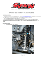
5. Remove both of the front sway bar end links from the axle using a 18mm wrench and the sway bar using a 15mm
socket. The upper link can be dislodged by striking the link as shown. See Photo 1 & 2.
6. Place a floor jack underneath the axle for support and
complete the removal of the front shock absorbers us-
ing a 13mm socket. See Photo 3. Retain the stock
lower hardware for reuse.
7. Mark the position of the lower control arm cam bolt and
axle brackets for installation reference. See Photo 4.
8. If equipped with ABS brakes, remove the sensor wires
and clamps for the inside of the lower arms and save
clamps for re-use.
9. Remove the track rod bolt from the axle on the pas-
senger side only using a 18mm wrench. It may be
necessary to pry bar loose.
10. Remove the coil spring clip located on the bottom coil
seat on the driver side of the vehicle using a 13mm
socket. Lower the axle and remove the coil spring. A
coil spring or strut compressor may be needed to remove the stock coil spring.
11. Remove the stock lower control arm by removing the nut, cam, and cam bolt (if equipped) from the axle bracket
and then removing the nut and bolt from the frame bracket using a 21mm socket / wrench, one side at a time.
12. Install the new Rough Country control arm on the frame and axle using factory hardware. See Photo 5. – DO
NOT tighten control arm bolts until vehicle is on the ground.
PHOTO 3
PHOTO 1 PHOTO 2
PHOTO 4 PHOTO 5
REMOVE THE LINK FROM AXLE REMOVE LINK FROM THE SWAY BAR
MARK STOCK CAM LOCATION
REMOVE LOWER SHOCK HARDWARE INSTALL NEW LOWER CONTROL ARM

13. If applicable, drill a 23/64” hole into each lower link and reinstall the ABS sensor wires. Use the original clamps.
14. A coil spring or strut compressor will be needed for the new coil spring installation. Install the new spring into the
upper and lower spring pockets and carefully remove the compressor. Make sure the coil is seated properly in
the coil seat by rotating the spring so the pig tail end fits in the spring pocket. See Photo 6.
15. Install the coil spring clamp and torque the spring clip bolt to 16ft.-lbs using a 13mm wrench.
16. Repeat steps on other side.
17. On the front track bar mount. From center of stock track bar hole measure directly over 3/4” and mark using a
punch as shown in Photo 7. Drill the new track bar hole using a 7/16” drill bit making sure to keep drill level. Do
not reinstall the track rod at this time. This will be preformed in a later step with the vehicle on the ground. Note:
This step will not be performed if the optional Adjustable Track Rod was purchased. If installing the optional track
rod, please wait until the vehicle is on the ground to center the front end.
18. Install new front shock absorber part #658693 in the factory lower mount
using stock hardware with the body side down. See Photo 8.
19. Install the new upper stud bushings and tighten the upper mounting
point only until bushing bulges slightly. Tighten the bar pin on the bottom
of the shock with the stock hardware.
20. Repeat this on the opposite side of the vehicle.
21. Install the tires, wheels and lug nuts. Lower the vehicle to the ground
and tighten the lug nuts to the factory specifications (80-110 ft. lbs) using
crossing pattern..
22. Install the sway bar hoop (u-shaped bracket) on the bottom side of front
sway bar where the stock link was secured using the supplied 3/8” x
1.25” bolt, washer, and flanged lock nut. Run bolt from inside to outside.
23. Lightly grease and install the 12mm sleeves (larger ID sleeves in bag)
provided on the bottom and top of the bent sway bar link. Use the fac-
tory hardware to install lower end of link. Place large face washer be-
tween bushing and nut. See Photo 9.
24. Install the upper part of the new link in the hoop bracket with the 12mm
bolts & flanged nut. See Photo 9 and 10. Note: The bolt must be in-
stalled with the nut to outside of vehicle to provide adequate clear-
ance to the frame.
PHOTO 10
PHOTO 7
Note:
Direction of bolt
on uppers sway
bar mount. Nut
goes to the out-
side.
PHOTO 9
Note: The offset
of the sway bar
link goes toward
the frame.
PHOTO 6
PHOTO 8
INSTALL NEW COIL SPRINGS MARK AND DRILL USING A 7/16” BIT
TIGHTEN LINK ON AXLE MOUNT

25. Longer brake lines are not required in the front
or rear with this kit unless the sway bar is dis-
connected or this lift is combined with another
lift. If disconnects are used, longer brake lines
are required and available from Rough Country.
26. Tighten the lower suspension arms to frame
bracket. Tighten to 130 ft. lbs. (both sides).
27. Align the reference marks on the adjustment cams
and lower arm axle brackets and tighten to 130 ft.
lbs.
28. Check to be sure the body is centered over the
axle. Unlocking the steering wheel and turning the
wheel to move the body, do this until the newly
drilled track rod extension hole line up. Install the
track rod with the stock bolt/flag nut and using a
15mm wrench. See Photo 11. Torque to factory
specs.
PHOTO 11
Reuse Factory
Hardware
INSTALL TRACK ROD ON AXLE

REAR INSTALLATION
1. Chock the front wheels. Jack up the rear of the vehicle and remove the tires and wheels. Place jack stands on
the frame rail to support the vehicle. Place a floor jack under the differential.
2. Remove the stock shock absorbers using a 13mm on the upper mount and a 18mm on the lower mount. Retain
the stock hardware for reuse.
3. Remove the stock sway bar links from the frame and the sway bar from the axle using a 15mm socket.
4. On the rear driver side of the vehicle unbolt the track rod from the axle and secure out of the way Retain the fac-
tory hardware for reuse.
5. Carefully lower the axle with the floor jack and remove the coil springs. NOTE: It may be necessary to use a coil
spring or strut compressor to remove the stock coil springs. Take care not to overextend the vent tube on the
axle. It may be necessary to unclip the diff vent hose during installation and reroute the hose after installation.
See Photo 1.
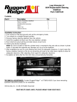
4. Disconnect the track bar from the axle bracket on driver side of vehicle and install the new track bar relocation
bracket in the stock location. Secure using the factory hardware and supplied sleeve as shown in Photo 2.
5. Using the bracket hole as a guide and using a 5/16” drill bit, enlarge the 2 holes in the axle mount to accommo-
date the 5/16” x 1” bolts.
6. Install the 5/16” bolts, washers, lock washers, nuts and tighten. Do not install the track rod in the new bracket at
this time. See Photo 3.
7. Remove and replace one suspension arm at a time. Remove the lower arm axle and frame mount bolts using a
21mm socket/ wrench. See Photo 4.
PHOTO 1
PHOTO 3
12mm x 65mm
bolt installs here
Stock bolt installs
here
Install 5/16” x
1” bolts here
PHOTO 2
PHOTO 4
UNCLIP LINE AND REROUTE AS NEEDED INSTALL BRACKET, SLEEVE AND HARDWARE
REMOVE LOWER ARM
INSTALL TRACK BAR BRACKET HARDWARE

8. Install new lower arm to the frame and axle mount brackets using original hardware. See Photo 5. DO NOT
tighten control arm bolts until vehicle is on the ground. If upper adjustable arms or Cam setup have been
purchased for upper arms install them at this time. Repeat these steps on the other side.
9. Install the new Rough Country coil springs as shown in Photo 6 making sure the rubber isolator is positioned in
the upper mount. It will be necessary to use a coil spring or strut compressor to install the new coil springs.
10. Jack up the axle to compress the coil spring and to a align the track rod with the new mounting point and install
using a 12mm x 65mm bolt and flange lock nut. See Photo 7.
11. Assemble shock # 658696 with the shock bushings and sleeves. Install the shocks on the vehicle with the factory
hardware as shown in Photo 8. Tighten the bar pin on the top of the shock with the stock hardware using a On
the lower mount install the supplied washer next to the bushing on its outside face. Note: If the rear sway bars
are disconnected a shock relocation bracket will be needed to prevent potential rubbing. This bracket is
available from your Rough Country distributor.
12. Reinstall the wheels and tires. Lower the vehicle to the
ground and tighten the lug nuts to the factory specifica-
tions (80-110 ft. lbs) using crossing pattern.
13. On the rear, slightly grease and insert the sway bar
bushings and 10mm sleeves in the new rear extended
sway bar links.
14. Secure the links to the stock location, using the 10mm
x 60mm bolt, washers and nuts supplied. On the upper
mounts you will reuse the factory winged nut. Tighten
to 40 ft. lbs using a 15mm socket / wrench. See
PHOTO 9.
15. Tighten lower arm pivot bolts to 130 ft. lbs and the rear
track bar mounting bolts to 74 ft. lbs.
16. Install transfer case drops or if purchased drive shaft/
SYE combination at this time per the instructions in-
cluded in packaging.
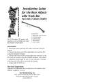
PHOTO 5 PHOTO 6
PHOTO 7 PHOTO 8
PHOTO 9
INSTALL LOWER CONTROL ARM INSTALLCOIL SPRING
REINSTALL TRACK ROD IN BRACKET INSTALL SHOCK ABSORBERS
INSTALL SWAY BAR LINK

TRANSFER CASE DROP BRACKET INSTRUCTIONS
1. Place the transmission in neutral, chock wheels, and place floor jack under the transmission mount skid plate.
2. Using a floor jack, support the skid plate.
3. Slightly loosen the bolts on the transfer case skid plate on both sides to allow for some movement. Do not re-
move the bolts. See Photo 1.
4. Proceed to other side. NOTE: Do not attempt to take out the bolts on both sides simultaneously. Installation is
done one side at a time. Remove the three bolts holding the transfer case skid plate to the frame rail.
5. Using the floor jack, slightly lower the skid plate and insert the transfer case lowering spacer as shown in Photo
2. (Note the shorter of the two brackets will be installed on the passenger side on the 97-02 models)
6. Using the bolts supplied with the kit slightly tighten the bolts. Do not fully tighten to allow for some movement for
the opposite side.
7. Proceed to the opposite side of the vehicle and install the brackets as instructed above. After installing both
sides, tighten bolts.
Note: If your vehicle is equipped with a 4 speed automatic and is a 2003-2006 you will have an additional cross
member connected to the transfer case by a plate. On this vehicle a total of 2 spacers are used per side. In situa-
tions where you are using this vehicle with the front sway bars disconnected (and during full droop during installation)
the front drive shaft may hit this cross member.
PHOTO 1 PHOTO 2
REMOVE STOCK HARDWARE INSTALL T-CASE SPACERS

SHIFT CONTROL BRACKET INSTALLATION
This step is performed only when transfer case drop is used. It is not required if drive shaft/SYE combination is being
installed.
1. From underneath the vehicle, locate the shift control bracket. It is attached to the inside of the transmission tunnel
on the driver side and acts as a pivot for the transfer case shift lever.
2. Remove the shifter linkage from the shifter plate that is mounted on the body tunnel as shown using a 10 mm
wrench. See Photo 1.
3. Reinstall the stock shifter bracket on the new drop bracket as shown with the 1/4” x 3/4” hardware. Tighten using
a 7/16” wrench. See Photo 2.
4. Install the supplied drop bracket on the stock tunnel bracket with the supplied 1/4” x 3/4” bolts/washers & nuts.
Tighten hardware using a 7/16” wrench. Check clearance on bolts. See Photo 3 & 4. In Photo 3, bracket is
shown removed to show mouting location. It is not necessary to remove the bracket although it can be removed
to ease installation.
Due to factory variations on the shifter rod bracket, it may be necessary to modify the shifter bracket by
slightly bending the mount on the rod to clear the shifter bracket or shifter bracket bolts. After noting how
much to bend the bracket to clear, remove the shifter assembly and bend the bracket as shown to slightly
clear the bracket / bolts. Do not over-bend!! See Photo 13.
Before After
PHOTO 13
PHOTO 2 PHOTO 1
INSTALL ASSEMBLY ON MOUNT SHIFTER ASSEMBLY SHOWN
PHOTO 3 PHOTO 4
BRACKET SHOWN INSTALLED ON MOUNT ASSEMBLY SHOWN INSTALLED IN MOUNT

FLOOR PAN MODIFICATION ( MANUAL TRANS ONLY)
This step is only necessary if the vehicle exhibits problems shifting after the lift installation is complete. Test drive the
vehicle and shift through all gears. If it is difficult to shift into ( or the transmission jumps out of) Second , Fourth, or
Reverse, the shifter may be contacting the edge of the transmission tunnel due to the transfer case drop and might
need to be modified slightly. Examine the area and if the shifter is contacting in this area, proceed to the steps below.
If the boot is causing the bind the console can also be relocated or shifted approx 1” and remounted to allow the full
shift pattern to be obtained. Only trim if necessary on the tunnel cover.
1. Move the seats to full rearward position.
2. Pry up the shift boot and bezel from the floor console.
3. Remove the bolts attaching the console to the floor pan and lift
the console upward and remove.
4. Remove the 4 screws attaching the cover boot to the cover and
slide the boot upward to expose the opening in the floor pan.
5. Shift the transmission into 2nd and reverse verifying a minimum
of 1/8” clearance between the shifter lever and the floor pan. If
necessary, enlarge the opening in the floor pan with a round file
See PHOTO 1.
6. Reposition the boot clock wise to match the increased floor pan
opening. Mark and drill three new mounting holes. Reinstall the
cover boot, console, and shift boot.
7. Reinstall the cover boot, console, and shift boot.
PHOTO 1
TRIM AS NEEDED

POST INSTALLATION INSTRUCTIONS
1. Check the transfer case shifter to see if it will move to 4L.
If not, the linkage will need adjusting as follows. Place the
shifter in 4L, loosen adjustment bolt and push the linkage
forward until it stops. Now re-tighten adjustment bolt.
Check to be sure 4WD works properly. See PHOTO 1.
2. Check all fasteners for proper torque. Check to ensure for
adequate clearance between all rotating, mobile, fixed,
and heated members. Verify clearance between exhaust
and brake lines, fuel lines, fuel tank, floor boards and wir-
ing harness. Check steering gear for clearance. Test and
inspect brake system.
3. Perform steering sweep to ensure front brake hoses have
adequate slack and do not contact any rotating, mobile or
heated members. Inspect rear brake hoses at full exten-
sion for adequate slack. Failure to perform hose check/
replacement may result in component failure. Longer replacement hoses, if needed can be purchased from a lo-
cal parts supplier.
4. Rotate driveshaft and check for interference at differential yoke and CV joint. If necessary, lightly dress casting(s)
and/or U-joint tabs in order to eliminate binding
5. Adjust headlights to proper settings.
6. Have a qualified alignment center realign front end to factory specs. As a general rule you set caster to the mini-
mum of the factory spec and set toe-in to the maximum.
7. Install Warning to Driver decal on sun visor.
8. Grease all control arms and periodically grease as required.
9. Re-torque all nuts and bolts after the first 100 miles, again after another 100 miles and then check periodically
thereafter.
10. All components must be retightened after 500 miles, and every three thousand miles after installation
PHOTO 1
ADJUST LINKAGE AS NECESSARY

Thank you for purchasing a Rough Country Suspension System.
TROUBLESHOOTING TIPS
Problem: Driveline Vibrations
Possible Solution: Check all u-joints to insure that there is no wear on the existing hardware caps. Even a new
vehicle can cause vibrations in the angle on the U-joint is changed after being run for even a short period of time.
Possible Solution: Driveline vibrations can be caused from the removal or addition of the hardtop which changes the
rear vehicle weight, and the rear height, which affects the rear drive shaft pinion angle. Rough Country adjustable
upper control arms or upper rear cam bolts, will eliminate such vibrations by adjusting / rotating the rear pinion angle
up or down as needed.
Possible Solution: The transfer case drop brackets must be installed with the 4” lift, if you do not plan to run a slip
yoke eliminator.
Problem: Your Jeep does not steer, or track correctly.
Possible Solution: If the steering is short or offset after installing the lift, the alignment shop should adjust the
linkages on the front axle to line the steering geometry back.
Possible Solution: If you are experiencing bump steer or axle float after the alignment, you will need to check the
track bar to ensure that the tie rod end is not worn or damaged. This will allow the axle to float from side to side. You
will also want to be sure that you drilled and installed the hardware for the support hole on the front track bar bracket.
If the bolt is not installed it will allow the bracket to move and give the same floating effect.
Problem: You experience “High Speed Wobble” after hitting bump at 35-40mph.
Possible Solution: “Death wobble” is usually a combination of items and typically there are is not one easy fix. We
recommend you follow these steps when trying to identify source. Start by looking for any loose movement in the
steering. Watch the tie-rod ends where they connect to the steering knuckle arms. Watch the drag link and the ends.
Watch the track bar—it should remain tight without side to side movement when dry turning. Check to make sure your
wheel bearing are in good condition by jacking up Jeep and grabbing top of the wheel and try to rock it back and
forth. Make sure your tires are balanced—we recommend they be “road force” balanced. Is your front end in
alignment? Lack of proper caster angles may be the problem. Last but not least is the steering stabilizer. A new
stabilizer will not fix the problem, but a worn out one will make the situations worse. Most aftermarket stabilizers
significantly dampen the movement that is the precursor to death wobble—control this and the severity is limited.
MAINTENANCE INFORMATION
It is the ultimate buyers responsibility to have all bolts/nuts checked for tightness after the first 500 miles and then
every 1000 miles. Wheel alignment steering system, suspension and driveline systems must be inspected by a quali-
fied professional mechanic at least every 3000 miles.
/