Page is loading ...

6”
6” 7” 8”
24” 30” 36”
12”
Rev:
Part No:
Page:
E.C.O. No:
CUSTOMER SERVICE PHONE: 1-800-426-8562
2355-048 1 of 6 7029-9961
OSU & Stanchion Assembly
ACTIVE COMPONENTS®
Scale 1 : 1
011/2
1/4 1/4
E
A
A A1
A3
A4
A4
A5
F
H H2H1
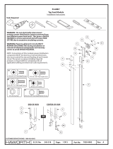
Tools Required
PARTS
Installation Instructions
A3
A2
OR
B
D
5/16 & 1/2”
Drill Bit
5/16 Hex Bit
1/4 & 3/16”
Allen Wrenchs Angle Drill
Attachment
OR
WITHOUT USB WITH USB
#8 x 5/8" Flat Head
Thread Forming Screw
(A4)
E
E
6”
6” 6”
12”
9”
42”
9”
48” - 72” (3 stanchions)
STANCHION/SUPPORT LOCATION FOR NOOK
C
L
C
L
#2
#2
#10-16 x 7/16" Pan Head
(F)

Rev:
Part No:
Page:
E.C.O. No:
CUSTOMER SERVICE PHONE: 1-800-426-8562
2355-048 2 of 6 7029-9961
1
E
C
L
6”
F
A
A
6”
12”
9”
42” - 72” (3 stanchions)
12”
6”
6” 6”
6”
6” 7” 8”
18” OR 24” 30” 36”
12”
STANCHION/SUPPORT LOCATION FOR SHELF
C
L
C
L
E1
E1
IMPORTANT
ALL SCREWS (F) MUST BE
INSTALLED BY HAND!
(VERY LOW TORQUE)
#10-16 x 7/16" Pan Head
(F)

2a
2b
Rev:
Part No:
Page:
E.C.O. No:
CUSTOMER SERVICE PHONE: 1-800-426-8562
2355-048 3 of 6 7029-9961
E
A
A
INTUITY RAIL MOUNTING
WORKSURFACE MOUNTING
OR
B
B
G
C
C
C
D
E
G
G
2”
5/16"
Drill Bit
5/16"
Drill Bit
1/2"
Drill Bit
G
5/16 x 2" Button Head Screw
(B)
(C)
5/16-18 x 1-1/2" Socket Head Cap Screw
A1

2c
Rev:
Part No:
Page:
E.C.O. No:
CUSTOMER SERVICE PHONE: 1-800-426-8562
2355-048 4 of 6 7029-9961
E
E
E
RESIDE MOUNTING
B
#10-12 x 1" Pan Head Screw
(J)
1
INTUITY - STABILIZER BRACKET (OPTIONS) AND ASSEMBLY ORDER
F
F
5/16 x 2" Button Head Screw
(B)
J
J1
Attach stanchion’s and stabilizer brackets
2Remove worksurfaces
3Install overhead 4Reinstall worksurfaces
IMPORTANT
ALL SCREWS (F) MUST BE
INSTALLED BY HAND!
(VERY LOW TORQUE)
#10-16 x 7/16" Pan Head
(F)

Rev:
Part No:
Page:
E.C.O. No:
CUSTOMER SERVICE PHONE: 1-800-426-8562
2355-048 5 of 6 7029-9961
STABILIZER BRACKET (OPTIONS)
F
F
H2
H2
#10-16 x 3/4" Self Drilling
Hex Head Screw
(E)
8”
14”
14”
NOTE: Stabilizer is not
required for 8” high units.
IMPORTANT
ALL SCREWS (F) MUST BE
INSTALLED BY HAND!
(VERY LOW TORQUE)
#10-16 x 7/16" Pan Head
(F)

Rev:
Part No:
Page:
E.C.O. No:
CUSTOMER SERVICE PHONE: 1-800-426-8562
2355-048 6 of 6 7029-9961
STABILIZER BRACKET (OPTIONS)
#10-12 x 1" Pan Head Screw
(J)
WITHOUT HATCH
WITH HATCH
H
H
J
J
F
FF
F
H1
H1
14”
8”
14”
NOTE: Stabilizer is
not required for 8”
high units.
NOTE: Any screw added
must have a clearance/pilot
hole where applicable.
IMPORTANT
ALL SCREWS (F) MUST BE
INSTALLED BY HAND!
(VERY LOW TORQUE)
#10-16 x 7/16" Pan Head
(F)
/


