Page is loading ...

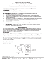
IMPORTANT SAFETY INSTRUCTIONS
For use with Planes Training Tables Quick Connect Power Flip Top Unit
When using an electrical furnishing, basic precautions should always be followed, including the following:
Read all instructions before using this table.
DANGER - To reduce the risk of electric shock:
1. Always unplug this furnishing from the electrical outlet before cleaning.
WARNING: TO REDUCE THE RISK OF BURNS, FIRE, ELECTRIC SHOCK, OR INJURY TO PERSONS:
1. Unplug from outlet before putting on or taking o parts.
2. Close supervision is necessary when this furnishing is used by, or near children, invalids, or disabled persons.
3. Use this furnishing only for its intended use as described in these instructions. Do not use attachments not recom-
mended by the manufacturer.
4. Never operate this furnishing if it has a damaged cord or plug, if it is not working properly, if it has been dropped or
damaged, or dropped into water. Return the furnishing to a service center for examination and repair.
5. Keep the cord away from heated surfaces.
6. Do not use outdoors.
7. Do not operate where aerosol (spray) products are being used or where oxygen is being administered.
8. To disconnect, turn all controls to the o position, then remove plug from outlet.
9. WARNING: RISK OF ELECTRIC SHOCK - CONNECT THIS FURNISHING TO A PROPERLY GROUNDED
OUTLET ONLY. SEE GROUNDING INSTRUCTIONS.
10. WARNING: RISK OF ELECTRIC SHOCK, FIRE, AND INJURY. REVIEW THE ASSEMBLY INSTRUCTIONS TO
CONFIRM THAT THE APPROPRIATE CRITICAL COMPONENTS AND ACCESSORIES ARE BEING USED WITH THE
FURNISHING.
SAVE THESE INSTRUCTIONS
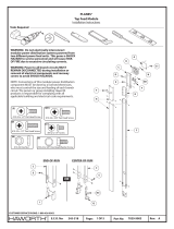
This product must be grounded. If it should malfunction or breakdown, grounding provides a path of least resistance for
electric current to reduce the risk of electric shock. This product is equipped with a cord having an equipment-grounding
conductor and a grounding plug. The plug must be plugged into an appropriate outlet that is properly installed and
grounded in accordance with all local codes and ordinances.
DANGER - Improper connection of the equipment-grounding conductor can result in a risk of electric shock.
Check with a qualied electrician or serviceman if you are in doubt as to whether the product is properly grounded.
Do not modify the plug provided with the product - if it will not t the outlet, have a proper outlet installed by a
qualied electrician.
This product is for use on a nominal 120-volt circuit and has a grounding plug that looks like the plug illustrated in sketch A
(see Figure 1). Make sure that the product is connected to an outlet having the same conguration as the plug. No adapter
should be used with this product.
Rev:
Part No:Page:E.C.O. No:
CUSTOMER SERVICE PHONE: 1-800-426-8562
21 of 10355-064 7029-9770
GROUNDED
OUTLET
(A) FIGURE 1
GROUNDED
PIN
GROUNDED
OUTLET BOX

Rev:Part No:Page:E.C.O. No:
CUSTOMER SERVICE PHONE: 1-800-426-8562
22 of 10 7029-9770
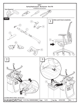
Tools Required
6mm 1/8" Drill
HSticker
S-89
OR
F
ELeg Assembly
G
Non-Locking Caster
K
End Cap
A
Top Assembly
B
S-1
S-1
Bumper
L
Cylinder
M
Beam
Locking Caster
or Glide
Training Table - Fixed & Flip Top
Installation Instructions
PLANES®
#10 x 1" Pan Head Screw
(S-1)
Fliptop Table - Parts
NOTE: Fixed Leg Table Assembly
starts on PAGE 4.
(S-89)
M8 X 40mm Socket Head Cap Screw
Scale 1 : 1
0 11/2
1/4 1/4
#2
355-064

Rev:Part No:Page:E.C.O. No:
CUSTOMER SERVICE PHONE: 1-800-426-8562
23 of 10 7029-9770
#10 x 1" Pan Head Screw
(S-1)
#10 x 1" Pan Head Screw
(S-1)
A
A
Install beam (M) to top assembly (A)
2Install cylinders (L) to beam (M) and Top (A)
3Push beam (M) down
1
S-1
M
M
S-1
L
L1
M
A
1
2
355-064
Depth
24”(610mm)
30”(762mm)
Width
36”(914mm)
42”(1067mm)
48”(1219mm)
54”(1372mm)
60”(1524mm)
66”(1676mm)
72”(1829mm)
36”(914mm)
42”(1067mm)
48”(1219mm)
54”(1372mm)
60”(1524mm)
66”(1676mm)
72”(1829mm)
Number of
Cylinders
1
1
1
1
1
2
2
1
1
1
2
2
2
2
“CLICK”

Rev:Part No:Page:E.C.O. No:
CUSTOMER SERVICE PHONE: 1-800-426-8562
24 of 10 7029-9770
Install leg assmblies (E)
4
Install end caps (K)
5
(S-89)
M8 X 40mm Socket Head Cap Screw
(S-89)
M8 X 40mm Socket Head Cap Screw
M
355-064
M
H
S-89
K
H
S-89
S-89
S-89
K
E
E

Rev:Part No:Page:E.C.O. No:
CUSTOMER SERVICE PHONE: 1-800-426-8562
25 of 10 7029-9770
355-064
M
Install casters (G & F)
6
F
OR
G
F
FG
Install bumpers (B)
7
#10 x 1" Pan Head Screw
(S-1)
S-1
B

Check legs (E)
NOTE: Loosen bolts (S-89)
then level table. Make sure
legs (E) do not twist when
re-tightening bolts.
TROUBLESHOOTING A WOBBLY TABLE
Check casters
E
1
2
1
2
3
4
1
E
S-89
6 of 10 Rev:
Part No:Page:E.C.O. No:
CUSTOMER SERVICE PHONE: 1-800-426-8562
27029-9770
355-064
Flip table
8

Leg Assembly
OR
E
F
Locking Caster
or Glide
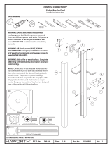
1/8" Drill
A
Top Assembly
M
Cable Trough
N
Reinforcement Bar
Tools Required
Training Table
Installation Instructions
PLANES®
Fixed Table - Parts
Scale 1 : 1
0 11/2
1/4 1/4
7 of 10
E.C.O. No: Rev:Part No:Page:
CUSTOMER SERVICE PHONE: 1-800-426-8562
27029-9770
#10 x 1" Pan Head Screw
(S-1)
S-1
Casting E-1
#2
355-064

A
A
N
M
Rev:Part No:Page:E.C.O. No:
CUSTOMER SERVICE PHONE: 1-800-426-8562
28 of 10 7029-9770
1
2
#10 x 1" Pan Head Screw
(S-1)
#10 x 1" Pan Head Screw
(S-1)
Install reinforcement bar (N)
Install cable trough (M)
S-1
S-1
355-064

A
A
F
G
#10 x 1" Pan Head Screw
(S-1)
4
OR
OR
OR
OR
OR
5
Install support legs (G & F)
Install casters (OPTIONAL)
Locking Caster
Non-Locking Caster
S-1
E
9 of 10
E.C.O. No: Rev:Part No:Page:
CUSTOMER SERVICE PHONE: 1-800-426-8562
27029-9770
355-064

PIE ASSEMBLY
S262
R
P
Q
Q
Q
P
R
S262 3
1/8"Drill
S262
N
P
P
1
2
1
2
M4 X 35mm Pan Head Screw
(S262)
M4 X 35mm Pan Head Screw
(S262)
Rev:Part No:Page:E.C.O. No: 210 of 10 7029-9770
CUSTOMER SERVICE PHONE: 1-800-426-8562
355-064
/


