Page is loading ...

Sukhoi SU 31M
Building instructions - Sukhoi SU 31M
1
Building instructions
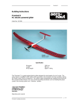
Sukhoi SU 31M
Electric RC model aircraft
Order No. 1352/00
Specification
Wingspan approx. 1410 mm
Length approx. 1120 mm
Wing area approx. 37 dm²
Tailplane area approx. 7.2 dm²
Weight approx. 2000 g
RC functions
- Elevator
- Ailerons
- Rudder
- Speed controller or motor switch
Recommended power system
actro CL 6 (Köhler) and actronic 40-18
12 cells 13 x 8” propeller
Fun 480/33/5,2 (Kontronik)
10 cells 14 x 8” propeller
12 cells 13 x 7” propeller
aero-naut Modellbau GmbH & Co. KG
Stuttgarterstr. 18-22
D-72766 Reutlingen
Germany
http://www.aero-naut.com
© aero-naut Modellbau GmbH & Co. KG

Sukhoi SU 31M
Building instructions - Sukhoi SU 31M
2
Preparation
Before starting construction connect the stand plates (1 + 2) using two lengths of hardwood
dowel (pieces of broom handle), ensuring that the fuselage fits between the plates with the
wing fitted.
Use 5-minute epoxy for all joints unless stated otherwise.
You will need four servos 30 mm long and 12 mm wide, with an output arm length of 15 - 18 mm.
For painting Depron parts (bottom wing fairing) we recommend water-based acrylic paints.
Photographs of the various stages of construction are printed on the sides of the kit box.
Fuselage
The first stage is to reinforce the fuselage (3) with several wooden parts. Glue part (8) across the
fuselage at the front, and the two side doublers (9) on either side (Figs. 8, 9 + 10). Note that the lugs
and notches of these three parts should slot together accurately. Slot the undercarriage support (10)
into the notches in parts (9), and glue it to the doublers and the fuselage (Figs. 10 + 11). Glue the two
captive nuts (39) to part (11) and glue this reinforcement in the fuselage over the undercarriage
support (10), working from above (Fig. 13). Screw parts (10 + 11) together using the nylon screws
(41). Glue the flight battery support (12) in the fuselage from the underside (Fig. 12). The stop-piece
(13) for the battery should not be glued in place until the model’s Centre of Gravity has been
established, in case the battery needs to be shifted further forward.
Glue the balsa screw supports (14) on both sides of the fuselage (3) at the nose to accept the cowl
screws (Fig. 17).
Glue the tailskid support plate (20) to the underside of the fuselage (Figs. 19 + 20), and glue the
tailskid (21) to the plate once the glue has set hard. Cut out the tailskid fairing (22), paint it, and fix it in
place using scrap decal sheet material.
The motor mount is assembled from parts (15 - 19). Sand the dark coloration from
the cut edges and remove dust before gluing. The motor mount plate (15) must be
positioned with the two slots on the left and the single slot on the right. Glue part
(16) in place with the two lugs on the left, and part (17) with the single lug on the
right (Figs. 14, 15 + 16). Glue parts (18 + 19) in place. Note that part (19) has one
angled edge to allow for the 2.5° right-thrust; this edge must be glued to part (18).
Glue the motor mount to the front face of the fuselage, aligning the pointed part of the motor mount
plate (15) with the fuselage moulding seam on both sides. This automatically sets the correct height,
so all you have to do is centre the motor mount. Secure the motor mount carefully so that it cannot
shift while the glue is setting.
Screw the two canopy retainer band hooks (49) in the balsa plates (50), and glue them on either side
of the fuselage below the canopy, adjacent to the battery compartment (Fig. 18). One hook should be
fitted to the balsa plate (51) and glued in the fuselage behind the canopy, between the vacant servo
wells and the control “snakes” (Fig. 18).
Glue the four threaded plastic sleeves (42) for the wing retainer screws in the fuselage (3) and to the
fuselage side doublers (9).
Tailplane and elevators
Apply the film strips (57) to the top surface of the tailplane to act as hinge reinforcements, with half
their width (20 mm) on the tailplane, half on the elevator.
Position the GRP horn (32) half-way along the CFRP tube (6) and glue the CFRP tube to the two
elevators (still attached to the tailplane (5)), with the GRP horn located in the circular recess (Figs. 1, 2
+ 3); note the angle of the horn (Fig. 3). Take care that no glue runs into the second channel (hinge).
Separate the two elevator panels from the tailplane at both tips using a sharp knife (Figs. 3 + 4). Cut
away the central area between the two elevators (Fig. 3); at a later stage this part is glued to the tail
end of the fuselage.

Sukhoi SU 31M
Building instructions - Sukhoi SU 31M
3
Small servos weighing around 13 g are required for this model; they should fit in the servo wells in the
fuselage from the underside (Fig 5). Fix the pushrod connectors (38) to the servo output arms using
the self-locking nuts provided.
The tunnels in the fuselage for the snake outer sleeves (36) can be pierced using a length of stout
wire. The exit slot for the rudder snake should be located about 50 mm forward of the tail end of the
fuselage on one side (Fig. 20). The elevator snake outer (36) should be central at the tail end, lining
up with the elevator horn (32) (Figs. 5 + 6). Please ensure that the snakes are as straight as possible
to avoid stiffness in the linkage; any curves must be of large radius. Glue the snake outers (36)
securely to the fuselage at several points. The pushrods (snake inners) are the steel rods (37). Form a
Z-bend in one end of the elevator pushrod and connect it to the middle hole of the elevator horn. Slip
the pushrod through the snake outer and
thread it through the pushrod connector
mounted on the elevator servo. Elevator
travel should be 20 mm up and 20 mm
down. Glue the tailplane to the fuselage.
Secure the pushrod (37) in the pushrod
connector (38) with a grubscrew, then snip
off excess rod length using side-cutters.
Fin and rudder
Apply the film strips (58) in the V-channels between the fin (7) and the rudder on both sides to
strengthen the hinge line. Separate the fixed rudder from the fin at the top by cutting forward (Fig. 7)
using a sharp balsa knife.
Form a Z-bend in one end of the rudder pushrod (37), slip it into the snake outer (36) and connect it to
the pushrod connector (38) mounted on the rudder servo. Temporarily tape the fin (7) to the tailplane
(5) and establish the correct position for the horn (33) on the rudder. Screw the horn (33) to the rudder
using the spreader and M2 screws (48), and cut off excess
screw length.
Cut a slot for the hinge (55) in the centre of the fuselage tail post
using a balsa knife, and glue the hinge in it. Cut a matching slot
in the rudder. Form a Z-bend in the pushrod (37) as for the
elevator and connect it to the inner hole in the rudder horn. Slip
the steel pushrod into the snake outer (36) and through the
pushrod connector (38) mounted on the servo. The fin can now
be glued to the tailplane, gluing the bottom hinge in the rudder at
the same time. Secure the pushrod (37) to the pushrod
connector (38) using a grubscrew, and cut off excess rod length
using side-cutters. The rudder should be capable of 50 mm
travel to each side of centre.
Final assembly - fuselage
The servos can be glued to the fuselage once you have checked the control surface (servo) travels.
Glue the fuselage turtle deck (4) to the fuselage (3).
The piece removed from the centre of the elevators can now be glued to the fuselage between the
elevators. Take care not to glue it to the elevators, as that would prevent them deflecting. Attach the
wheel axles (machine screws, part 45) to the GRP undercarriage unit (40) using the nuts (46) and
shakeproof washers. Fit the wheels (44) followed by the self-locking nuts (47). Fix the undercarriage
(40) to the fuselage using the nylon screws (41).
The next step is to cut three to five holes of around 10 mm Ø in the front face of the fuselage to
provide a cooling airflow; the motor cables also pass through them. Screw the motor to the motor
mount and run the cables back into the fuselage.
Attach the lower part of the cowl (23) to the fuselage with tape, followed by the top section (24). Drill
four 1 mm Ø holes through the cowl sections into the balsa screw supports (14) on either side of the
fuselage, and fix the cowl sections in place using the self-tapping screws (54). Remove the cowl, fill
the holes in parts (14) with a drop of epoxy, then fit a self-tapping screw in each and remove it again
immediately; the epoxy hardens the threaded holes. Tape the cowl sections together at the front using
adhesive film (scrap decal sheet material).

Sukhoi SU 31M
Building instructions - Sukhoi SU 31M
4
Canopy
Don’t cut out the canopy frame (25) yet.
Cut out the instrument panel from the decal sheet and apply it to the front of the canopy frame (25).
The pilot’s backrest can be painted a different colour if you wish. Cut out the canopy (26) leaving a
flange about 20 mm wide. Glue the canopy to the canopy frame. When the glue has set hard trim the
joined canopy parts leaving a flange 10 mm wide at the canopy recess. Glue the plywood support (27)
to the underside of the canopy frame (25). Bend a hook (49) at right-angles and glue it in place,
centred on the support (27); this hook must be set at right-angles to the fuselage centreline.
Tension a rubber band (53) from each of the two hooks (49) (in the front of the fuselage) to the rear
hook in the fuselage. When the canopy is fitted the two rubber bands are then engaged in the hook on
the bottom of the canopy.
Wing
Lay the two wing panels (29 + 29) upside down on a flat surface. Fit the carbon tube wing spar (30)
into both wing panels from the centre and glue all three parts together (Fig. 21). Apply the film strips
(56) to the top surface of the wing to act as hinge reinforcements; half the width (25 mm) should be on
the wing, half on the aileron. Before gluing the servos in the wing set them to neutral from the
transmitter (Fig. 22). The servo leads have to be extended as described in the RC system operating
instructions. The wing ribs are already cut away to clear the servo leads. At the centre section a hole
must be cut through the high-density foam in the direction of the centre of the wing, so that the servo
leads exit the wing on the top surface.
Glue the balsa supports (52) in the slots in both ailerons. Please take care that no glue gets onto the
aileron hinge. The spigot of the aileron horns (34) has to be shortened slightly; roughen the joint
surfaces and file notches in the spigot to provide a “key” for the epoxy. Glue the horns in the balsa
supports (52) (Fig. 22). The ailerons can now be cut through at the inboard end to separate them from
the wing (Fig. 24). To check the aileron system connect the pushrods (35) to the servo output arms
and the aileron horns, and secure them with the retainer clips (59) (Fig. 23). Aileron travel should be
30 mm to each side of neutral. When you are satisfied, remove the pushrods (35) again and glue the
servos in place. Position the bottom wing fairing (31) in the recess in the wing, and push the servo
output arms through the foam material. Remove the fairing and enlarge the slots slightly so that the
output arms and aileron pushrods have proper clearance when they move. The fairing (31) can now
be glued to the underside of the wing. This is best carried out in two stages: first glue the front edge
(behind the leading edge) and allow the glue to set hard, then glue the remainder of the fairing in
place. On the underside of the wing glue the four circular balsa reinforcements (60) for the nylon
screws (42) in the recesses designed for them.
Centre of Gravity
The model should balance at a point 85 mm aft of the wing root leading edge, measured directly
adjacent to the fuselage. Adjust the position of the flight battery to obtain correct balance.
Decals
Cut out the individual decals and apply them to the model in the arrangement shown in the kit box
illustration.
Control surface travels
Elevator: 20 mm each side
Rudder: 50 mm each side
Ailerons: 30 mm each side

Sukhoi SU 31M
Building instructions - Sukhoi SU 31M
5
Drawing of die-cut parts
Parts list
No.
Description No. off Material Notes
1
Front stand plate 1 High-density foam Moulded
2
Rear stand plate 1 High-density foam Moulded
3
Fuselage 1 High-density foam Moulded
4
Fuselage turtle deck 1 High-density foam Moulded
5
Tailplane 1 High-density foam Moulded
6
Tailplane spar, 5 x 415 mm 1 CFRP tube Ready made
7
Fin 1 High-density foam Moulded
8
Front fuselage reinforcement 1 Plywood 3 mm Die-cut
9
Side fuselage doubler 2 Balsa 2.5 mm Die-cut
10
Fuselage reinforcement, undercarriage 1 Plywood 3 mm Die-cut
11
Fuselage reinforcement, captive nuts 1 Plywood 3 mm Die-cut
12
Fuselage reinforcement, battery support 1 Plywood 3 mm Die-cut
13
Flight battery stop 1 Plywood 3 mm Die-cut
14
Fuselage reinforcement, cowl 2 Balsa 2.5 mm Die-cut
15
Motor mount plate 1 Plywood 3 mm Laser-cut
16
Motor mount, side piece 1 Plywood 3 mm Laser-cut
17
Motor mount, side piece 1 Plywood 3 mm Laser-cut
18
Motor mount, front 1 Plywood 3 mm Laser-cut
19
Motor mount, bottom 1 Plywood 3 mm Laser-cut

Sukhoi SU 31M
Building instructions - Sukhoi SU 31M
6
20
Tailskid reinforcement 1 Plywood 3 mm Die-cut
21
Tailskid 1 Steel rod 2 mm Ready made
22
Tailskid fairing 1 Plastic Vac. moulded
23
Bottom cowl section 1 Plastic Vac. moulded
24
Top cowl section 1 Plastic Vac. moulded
25
Canopy frame 1 Plastic Vac. moulded
26
Canopy 1 Plastic Vac. moulded
27
Canopy support 1 Plywood Die-cut
28
R.H. wing 1 High-density foam Moulded
29
L.H. wing 1 High-density foam Moulded
30
Wing spar, 5 x 970 mm 1 CFRP tube Ready made
31
Bottom wing fairing 2 Depron Die-cut
32
GRP elevator horn 1 GRP Ready made
33
Rudder horn 1 Plastic 7491/03
34
Aileron horn 2 Plastic 7491/01
35
Aileron pushrod 2 Steel rod 1.5 mm Ready made
36
“Snake” outer sleeve, 500 mm 2 Plastic
37
“Snake” inner, 1 x 500 mm, one Z-bend 2 Steel rod
38
Pushrod connector 2 Metal 7490/07
39
Captive nut, undercarriage 2 Metal 7766/04
40
Undercarriage unit 1 GRP Ready made
41
Nylon undercarriage screw, M4 x 70 2 Nylon Ready made
42
Nylon wing retainer sleeve, M6 4 Nylon 7329/66
43
Nylon wing retainer screw, M6 x 60/80 2 + 2 Nylon
44
Wheel, 70 x 4 mm 2 Plastic Ready made
45
Machine screw, M4 x 35 mm 2 Metal 7776/31
46
Nut, M4 2 Metal 7774/04
47
Self-locking nut, M4 2 Stahl 7766/24
48
Rudder horn screw, M2 2 Metal 7772/40
49
Canopy retainer hook 3 Metal 7800/00
50
Front hook plate 2 Balsa 2.5 mm Die-cut
51
Rear hook plate 1 Balsa 2.5 mm Die-cut
52
Aileron horn reinforcement 2 Balsa 2.5 mm Die-cut
53
Canopy retainer rubber band 2 Rubber Ready made
54
Self-tapping cowl retainer screw 10 Metal 7768/00
55
Hinge 1 Nylon 7495/00
56
Self-adhesive film strip, aileron 2 Plastic, 480 x 50 mm Ready made
57
Self-adhesive film strip, elevator 2 Plastic, 190 x 40 mm Ready made
58
Self-adhesive film strip, rudder 2 Plastic, 105 x 20 mm Ready made
59
Pushrod retainer clip 2 Plastic 7489/07
60
Wing retainer screw reinforcement 4 Balsa 2.5 mm Die-cut
61
Decal sheet 1 Self-adhesive film
62
Building instructions 1
/