Page is loading ...

Scarlet
Scarlet building instructions 1
Building Instructions
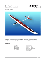
Scarlet RC model aircraft
Order No. 1308/00
Specification:
Wingspan approx. 3000 mm
Length approx. 1270 mm
Wing area approx. 53.5 dm²
All-up weight approx. 1.45 kg
Wing loading approx. 39 g/dm²
RC functions Aileron, elevator,
rudder, flaps,
throttle

Scarlet
Scarlet building instructions 2
Parts List
1) Fuselage, white pigmented 1 GRP, ready made
2) Canopy, black 1 Ready made
3) V-tail and control surfaces 2 (l + r) Wood construction, ready made
4) Wing centre section with flaps, covered 1 Styrofoam / wood, ready made
5) Outboard wing panels with ailerons, covered 2 (l + r) Styrofoam / wood, ready made
6) Aileron / flap servo covers 2 pairs Vacuum-moulded plastic
Contents of small parts bag:
7) Servo plate 1 Poplar plywood, machined
8) V-tail joiner rods 2 Steel, pre-formed
9) V-tail support rail 1 Balsa, ready made
10) V-tail horns 2 Pre-formed rod with ball-link
11) Wing joiners 2 GRP / CFRP, 8 Ø x 140 mm
12) Wing incidence pegs 2 CFRP, 3 Ø x 20 mm
13) Wing locating peg 1 Beech dowel, 4 Ø x 38 mm
14) Wing retainer screw 1 Nylon, M5 x 20 mm
15) Motor bulkhead 1 GRP, ready made
16) Short horns (aileron) 2 Plastic, ready made
17) Long horns (flap) 3 Plastic, ready made
18) Horns, spreader plate and screws 2 sets Plastic, ready made
19) Clevises with threaded couplers and pins 6 sets Ready made
20) Aileron / flap pushrods 4 Steel wire with Z-bend, 75 mm
21) Fuselage formers for tail snakes 1 Wood, ready made
22) V-tail pushrods 2 Steel wire, 0.8 Ø x 800 mm
23) Wing servo mount 4 pairs Wood, ready made
24) Captive nut 1 Ready made, M4
25) Captive nut washer 1 Wood, ready made
26) Canopy tongue 1 GRP, ready made
27) Canopy locating pin 1 1 Ø x 26 mm
28) Building instructions 1 Ready made
Essential accessories
Knife, metal file, straight edge, ruler, set of screwdrivers, 5-minute epoxy, thick and thin cyano-
acrylate, paper masking tape, soldering iron, 4 m x 0.14 sq mm twisted servo cable, 6-pin plug and
socket.
Recommended RC equipment
6 servos (each 9 - 13 mm)
Receiver (min. 5-channel)
Recommended power system
Motor: 500 Watt
Battery: 4S LiPo / LiIon

Scarlet
Scarlet building instructions 3
Wing
The wing (this and the following pictures show the “Noemi”; the “Scarlet” wings are similar) con-
sists of three panels: the centre section, which is attached to the fuselage by a single screw, and
two outboard panels, which are plugged into the centre section.
“Scarlet” is a high-performance electric-powered model glider. The wing consists of balsa-sheeted
Styrofoam panels with a CFRP spar, while the winglets are moulded in white GRP. The four-flap
wing provides effective aerodynamic support for various phases of flight.
Glue the GRP winglets to the tips of the outboard panels using a simple butt joint. Check that
these parts are positioned correctly, and wipe off excess glue where it is squeezed out of the joint.
The wing centre section is fixed to the fuselage by means of a single central screw. Use the tip of
a hot soldering iron to remove the film over the central hole; the tip of the iron will stick the film
down again. The beech locating dowel should now be glued in the centre of the leading edge:
place the wing on the fuselage, check that it is positioned correctly and at right-angles to the fuse-
lage centreline, then mark the position of the pre-cut hole on the leading edge.
Remove the film over the servo wells on the underside of the wing, using the soldering iron again.
The aileron and flap servos are installed using the ply-
wood mounts supplied. To establish the correct position,
fit the mounts on the servo and place this assembly in the
recess “dry” (without glue). You can now mark exactly
where the servo mounts are to be glued.
Glue the servo mounts in the wing using thick cyano or
epoxy. Allow the glue to cure completely before installing
the servos permanently.
Check that the output arms are exactly at right-angles to
the control surface hinge line, then fix the servos in the
mounts using hot-melt adhesive. Check from the transmit-
ter that the servos are exactly at neutral (centre). Set the
correct direction of rotation at the same time.
Cut off the servo leads. Draw a twisted servo extension lead (not included in the kit) through each
wing panel. You will need to fit a three-pin plug and socket at the joint between the centre section
and the outboard wing panels.
Solder the twisted extension leads to the aileron servos, and fit a separate heat-shrink sleeve over
each soldered joint. Alternatively - if you do not wish to cut the servo leads - you can use standard
commercial extension leads and connect the servo plugs to the sockets. In this case you should
wrap tape round the connectors to ensure that they cannot work loose over time.
A six-pin plug and socket have to be installed at the point where the wing centre section meets the
fuselage. All the positive servo wires can be soldered to one pin, and all the negative wires to an-
other pin, leaving four spare pins for the signal wires.
The horns should be glued in the flaps and ailerons exactly in line with the servo output arms.
The short horns are used for the ailerons; note that the linkage hole should coincide exactly with
the hinge pivot axis, and the horn should be exactly in line with the servo output arm. Glue the
longer horns in the flaps, exactly as described for the ailerons.

Scarlet
Scarlet building instructions 4
Each of the pushrods is assembled from a
pre-formed wire rod, a threaded coupler and
a plastic clevis. Solder the threaded coupler
securely to the rod; epoxy can be used as an
alternative.
When everything is in place and working
properly, carefully cut out the servo well co-
vers and tape them to the wing. Check that
the servo output arms do not foul the inside
of the covers.
Plug the outboard wing panels into the cen-
tre section using the CFRP / GRP joiners.
Note that the carbon joiners incorporate the
correct dihedral.
The incidence pegs can now be glued into
the outboard wing panels to prevent the
wings swivelling. Leave them projecting by
about 10 mm, and sand the projecting ends
to a rounded shape so that they are easy to
insert.
When you are flying the model, the wing panels can be secured with strips of adhesive tape ap-
plied along the joint line on the top surface.
The fuselage
The canopy is detachable, so that you can
quickly and easily swap the flight battery at
the flying site.
Glue the GRP tongue to the inside of the
canopy in such a way that it engages snugly
under the fuselage flange. The front end of
the canopy is located by a steel pin which
has to be glued in place. Alternative meth-
ods of attaching the canopy include adhesive tape or a pair of self-tapping screws.
Glue the snake outer sleeves for the V-tail linkage in the fuselage, with the formers already glued
to the wooden rail. Slide the whole assembly back into the fuselage as far as possible.
At the tail end the wood rail supporting the sleeves must be located on the bottom of the fuselage.
The wing retainer screw engages in a captive nut which should be glued to the underside of the
central hole in the wing saddle using 5-minute epoxy. Ensure that no glue gets into the threaded
section.

Scarlet
Scarlet building instructions 5
Glue the plate for the V-tail servos in the
fuselage under the opening in the wing sad-
dle. Thoroughly roughen the inside of the fu-
selage beforehand to ensure that the glue
adheres well.
Check that the servos fit in the apertures
before gluing the plate in the fuselage!
Screw the servos to the servo plate using the
retaining screws and rubber grommets sup-
plied in the servo accessory pack.
Connect the steel pushrods to the servo
output arms using the threaded couplers and
clevises supplied.
V-tail
The two steel joiner rods for the V-tail have to
be glued in the fuselage: start by fixing the
fuselage on the workbench with the wing
saddle horizontal. Ensure that it cannot shift,
and that you can see clearly into the tail end.
Fit the rods and the balsa support rail in the
fuselage as shown. Use a metal file to
roughen the joint areas inside the fuselage to
ensure that the glue adheres well.
Now fit the V-tail panels on the joiner rods
and align them accurately.
The included angle of the tail panels is 110
degrees. If the tail panels cannot be pushed
fully against the fuselage, the joiner rods
need to be shortened slightly.
When you are confident that the tail panels
are correctly positioned, glue the steel rods in
the fuselage using 5-minute epoxy, taking
care to produce really sound joints. Fix the
tail panels so that they cannot shift. Allow the
epoxy to cure completely (preferably over-
night) before you remove the tail panels
again.
The pushrods in the fuselage are connected
to the V-tail panels by means of pre-formed
steel rod horns with linkage balls attached;
glue these in the tail control surfaces as
shown. The ball-links allow the linkages to be
disconnected easily, and they can also be ad-
justed by screwing in or out on the threaded
couplers.
Installing the motor
The first step is to glue the GRP motor bulk-
head in the fuselage. Press it firmly against
the fuselage while you tack it in place with
thin cyano; it can then be glued permanently
using 5-minute epoxy. Keep the bulkhead
exactly parallel to the front edge of the fuse-
lage: the motor shaft must be angled slightly
down (about 2°) and very slightly to the right
(as seen from the tail; about 1°).

Scarlet
Scarlet building instructions 6
Allow the glue to set hard before fitting the spinner on the motor shaft. You may need to sand back
the front face of the fuselage slightly to obtain a perfect match with the diameter of the spinner.
Work slowly, checking constantly, and you will be rewarded with a perfect result.
Now screw the motor to the bulkhead and connect it to the speed controller, taking care to main-
tain correct polarity. It is best to check this before the motor is installed: drill a central hole in a
small piece of scrap wood and push it onto the motor shaft to help you check the direction of rota-
tion. Do not fit the propeller at this stage: injury hazard!
Assemble the folding propeller, hub and spinner as described in the instructions supplied with the
set.
The speed controller can be attached to the inside of the fuselage with hook-and-loop tape, or
installed below the battery plate. At the same time secure the wires between the speed controller
and the motor so that they cannot possibly come into contact with the motor. Do not pack the
speed controller in foam, as this could lead to overheating.
Fix the flight battery to the bottom of the fuselage, again using hook-and-loop tape.
Final stages
Set the correct Centre of Gravity (68 - 72 mm from the root leading edge) by adjusting the posi-
tion of the flight battery. This C.G. range is safe for the first few flights. You may wish sub-
sequently to fine-tune the model’s balance to suit your personal preference - but not by more than
+/- 5 mm.
Fix the battery in the fuselage with hook-and-loop tape, and mark its final position so that you can
be confident of replacing it correctly for subsequent flights.
Check the control surface functions, and set the control surface travels as stated below:
Rudder, right turn: left tail panel 20 mm up, right tail panel 17 mm down;
Rudder, left turn: left tail panel 17 mm down, right tail panel 20 mm up;
Up-elevator: both tail panels 20 mm up;
Down-elevator: both tail panels 17 mm down;
Ailerons, right turn: right aileron 12 mm up, left aileron 8 mm down;
Ailerons, left turn: right aileron 8 mm down, left aileron 12 mm up;
Landing: both ailerons 15 mm up
both flaps 85 degrees down
5 mm down-elevator (both tail panels)
The final task is to apply the plotted stickers to the model, following the arrangement shown in the
kit-box illustration.
The first flight
Once you have completed all the checks, there is nothing to stop you carrying out the model’s first
flight. If you have little or no experience in model flying, we urgently recommend that you join a
model flying club and ask a proficient model pilot to help you: he will carry out the initial test-flights
for you, and then help you to learn the art of model flying step by step.
It is also possible to learn to fly without outside help: first wait for a day with little or no breeze.
Launch the model with a firm push forward into any wind, keeping the wings and fuselage level.
Allow the aircraft to climb at a shallow angle, initially using the elevator only to adjust the rate of
climb; don’t let the model slow up too much. If it turns to one side, gently move the rudder in the
opposite direction to return to straight flight.
Once the model is at a safe altitude, switch the motor off and allow it to glide. Use the controls
very gently at first until you feel familiar with the aeroplane’s response to commands. Don’t get
over-confident too quickly, and maintain plenty of height at all times - model flying is a sophis-
ticated skill which needs to be learned - just like driving a car or riding a bike.
Always land the model with its nose pointing directly into wind. Let it glide towards the ground at a
shallow angle, and don’t apply up-elevator until it is just about to touch down. Never carry out any
major corrections with the rudder when the model is close to the ground!

Scarlet
Scarlet building instructions 7
Safety notes, hazard warnings
Model flying is a fascinating hobby. However, we urge you to observe the following basic rules
when flying a model aircraft, as this will avoid annoying and endangering other people.
In Germany you are only permitted to fly model aircraft using a 35 MHz or 2.4 GHz radio control
system.
Your model should only be flown at a site where you will not annoy or endanger anyone; it is al-
ways best to use approved model flying sites.
Never fly towards or over spectators. Keep any high-risk flying manoeuvres well away from other
people.
Never attempt to repair your radio control system; always leave such work to the experts. Any
home modifications to your RC system inevitably invalidate its official approval.
Do not switch your transmitter on until and unless you have ensured that you will not cause inter-
ference to any other radio control systems in the vicinity; typically through a “channel clash” (two
transmitters on the same frequency).
If possible, join a model flying club, where you will find plenty of friendly people to help with all
your queries and problems.
Please note: if damage ensues due to failure to observe these instructions, the guarantee is rendered invalid. We ac-
cept no liability for consequent damage which results from such actions. Please follow the building instructions to the
letter when completing and operating this model. The building instructions include information on safe flying. This
model is in no respect a children’s toy.
aero-naut Modellbau GmbH & Co KG, Stuttgarter Strasse 18-22, 72766 Reutlingen, www.aero-naut.com
/