Page is loading ...

Premiant II
Premiant II building instructions
1
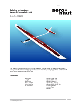
Building Instructions
Premiant II
RC electric-powered glider
Order No. 1317/00
Specification
Wingspan: 2000 mm
Length: 985 mm
All-up weight: approx. 1100 g
The “Premiant 2” is a good-natured electric glider designed for wind speeds of up to 4 m/sec. The
wings feature a modified “E-393” airfoil, which guarantees slow airspeeds and easy handling, making
the model a good choice for beginners. The model’s major components are supplied factory-built and
film-covered; all that remains is to carry out final assembly procedures such as installing the power
system, the receiving system and - if desired - spoilers.
“aero-naut” Modellbau
Stuttgarterstr. 18-22
D-72766 Reutlingen
Germany
http://www.aero-naut.de

Premiant II
Premiant II building instructions
2
Parts List
1.) Fuselage, pigmented white 1 GRP, ready made
2.) Canopy, pigmented blue 1 GRP, ready made
3.) Rudder, covered 1 Wooden construction, ready made
4.) Tailplane and elevator, covered 1 Wooden construction, ready made
5.) Inboard wing panel with spoiler, covered 2 (l + r) Wooden construction, ready made
6.) Outboard wing panel with aileron, covered 2 (l + r) Wooden construction, ready made
7.) Spoiler and horn, covered 2 (l + r) Wooden construction, ready made
8.) Former assembly with snakes and steel inners 1 Ready made
9.) Tail post 1 Balsa, 7 / 12 x 149 x 5 mm
10.) Servo plate, two apertures 1 Poplar plywood, 47 / 53 x 67 x 3 mm
11.) Shaped balsa parts for servo mount 3 Balsa, 10 mm
12.) Battery support 1 Poplar plywood, 175 x 41 x 3 mm
13.) Shaped balsa part 1 Balsa, 6 mm
14.) Balsa former 1 Balsa, 4 mm
15.) Wing panel joiner, angled 2 Beech, 6 Ø x 56 mm
16.) Aileron servo well cover 2 Plywood, 41 x 47 x 1 mm
17.) Spoiler servo well cover 2 Plywood, 44 x 54 x 1 mm
18.) Wing joiner rod 1 Steel, 5 Ø x 245 mm
19.) Wing joiner tube 1 Brass, 6 Ø x 65 mm
20.) Motor bulkhead 1 GRP, ready made
22.) Rudder hinge 2 Ready made
22.) Aileron and rudder horn 3 GRP, ready made
23.) Elevator horn 1 GRP, ready made
24.) Clevis, threaded coupler and screw 4 Ready made
25.) Aileron pushrod 2 Steel rod, one Z-bend
26.) CFRP rod 2 3 Ø x 80 mm
27.) GRP canopy retainer tongue 2 Ready made
28.) Spruce strip 2 5 x 2 x 22 mm
29.) Self-tapping screw 4 1.9 x 6.5 mm
30.) Nylon screw 2 M3 x 15 mm
Essential items required to build the model
Building board (e.g. 16 mm hardwood board), balsa knife, ruler, straight edge, white glue, screwdriver,
5-minute epoxy adhesive, abrasive paper, modelling pins, paper masking tape.
Recommended RC equipment
1.) 4 - 6 servos (9 - 13 g types)
2.) Receiver (min. 3 - 5 channels)
Recommended power system
1.) Motor: Actro C8 18A
2.) Speed controller: Actronic 45 BEC
3.) Folding propeller: 14 x 7”
4.) Flight battery: 7 NiCd / NiMH cells, or 3S LiPo, 1200 mAh
Wings
Each wing consists of two panels, which are of traditional built-up construction and are supplied
assembled and film-covered. The two panels for each wing are simply glued together; the mating
ribs are already set at the correct angle.
Pin down one inboard wing panel flat on the building board. Slip a small piece of clear plastic film
under the outboard facing rib, to prevent the wing becoming stuck to the board.
Prepare a twisted servo extension lead (not included in the kit), thread it through the inboard wing
panel, and into the outboard wing panel.
Locate the angled dihedral brace, and apply a thin coating of epoxy glue to it and the joint surface
of the outboard wing panel. Press the two panels together, pack up the tip at the appropriate angle
with a temporary support, and apply tape over the joint to hold the parts together. Check that the
two panels are not twisted relative to each other: the rib outlines must line up exactly. Carefully

Premiant II
Premiant II building instructions
3
wipe away excess epoxy on the top surface.
Allow the glue to cure completely (!), then remove the joined wing from the building board, and
remove any excess adhesive on the underside with careful use of a sharp knife.
Repeat the whole procedure for the second wing panel.
The next step is to install the aileron servo in each wing: use the tip of a small soldering iron to
remove the covering film over the servo well; the hot iron will stick the edge of the film to the
structure.
Solder the aileron servo lead to the twisted extension lead before placing it in the servo well.
The servo is held in place by the plywood well cover, which is fixed to the wing with clear adhesive
tape. An alternative method is to use retaining screws. We do not recommend that you glue it in
place, as this would make it more difficult to access the servo in case of damage. Cut a slot in the
servo well cover to provide clearance for the servo output arm and aileron pushrod before fitting it.
Glue the GRP horn in the slot in the aileron - exactly in line with the servo output arm.
The aileron linkage consists of a short pre-formed steel pushrod, a threaded coupler and a plastic
clevis. Repeat the whole procedure with the second aileron servo.
Spoilers?
At this juncture you can decide whether you wish to install working spoilers in your model, al-
though it is also possible to install them once the model is complete. Tip: spoilers enable you to
carry out steeper, shorter landing approaches, and are also useful for losing height when the lift is
uncomfortably strong.
Each spoiler servo lead should be soldered to a second twisted extension lead before it is installed
in the servo well.
Use high-quality adhesive tape as hinge material for the spoilers (exactly as for the ailerons and
the elevator). The spoilers are raised directly by the servo output arms, and closed and held
retracted by the steel wire which is already in place; the steel wire is connected to the GRP spoiler
horn.
Take your time over setting up the servo output arm to ensure that the spoilers open and close
smoothly and reliably.
The plywood servo well covers are again held in place using clear adhesive tape or small screws
(not included in the kit).
Fuselage
The first step is to install and align the assembled snake / former unit in the fuselage, working from
the front.
The rudder snake should be routed out of one side of the fuselage, but first you must cut away the
channel along the marked lines. Glue the snake outer sleeve to the fuselage at the exit point, then
cut it off flush with the fuselage side when the glue is hard.
Locate the elevator snake outer (with wood block attached) and pull it up inside the fin. Glue it in
place in such a way that the elevator can be actuated directly, without any tight bends in the
snake.
The formers can be glued in place by applying drops of epoxy at the joint positions using a length
of steel rod or similar as a tool.
The servo plate is assembled from a set of
wooden parts as shown in the illustration.
Glue the parts together using thick cyano or
white glue, then glue the whole assembly in
the fuselage using epoxy.

Premiant II
Premiant II building instructions
4
The battery support can now be fixed on top
of the assembly using four self-tapping
screws.
The wing joiner tube is installed next: start
by sanding the surface thoroughly to ensure
a sound glued joint. The tube is installed in
the rear of the two large holes. Before ap-
plying glue, offer up both wing panels and
check that the top of the airfoil is aligned
neatly with the wing root fairing on the fuse-
lage. If there is a slight discrepancy, adjust
the holes to suit.
Epoxy the brass tube in the holes, applying
plenty of epoxy on the inside of the fuselage.
Drill a hole just aft of the joiner tube in both sides of the fuselage, and file the holes out to form
slots, through which the aileron and spoiler servo leads can be passed when the model is rigged.
The wing incidence pegs take the form of two short 2 mm Ø rods which are glued in the pre-drilled
holes in the root facing ribs. Drill matching 2 mm Ø holes in the fuselage to accept the rods. Check
carefully that the wing roots line up accurately with the root fairings.
The wings are retained on the fuselage using strips of clear adhesive tape which are applied on
the top surface along the separation line.
Tailplane
You will find pre-drilled holes in the tailplane for the retaining screws. Remove the film over the
holes, position the tailplane accurately on the saddle, and mark the hole positions on the top of the
fin.
Cut an M3 thread in both holes in the fuselage using a suitable steel machine screw: this is
accomplished by drilling 2.5 mm Ø pilot-holes, and cautiously driving the screw into the holes.
Remove the screws and apply a small drop of thin cyano to each hole to harden the threads. Allow
the glue to cure fully before fitting the retaining screws!
The tailplane can now be attached to the fuselage using two nylon screws.
Glue the small GRP horn in the slot in the elevator, and check that it is possible to connect the
snake inner: glue a threaded coupler to the end and screw a clevis on it. You may need to shorten
the snake outer sleeve in order to obtain sufficient down-elevator travel.
Rudder
Glue the tail post in the tail end of the fuselage, keeping the edges flush.
Insert two hinges in the tail post and secure them with small wire pins pushed through the
fuselage / fin and the hinges.
Complete the linkage by gluing a GRP horn in the rudder, soldering a threaded coupler to the end
of the steel pushrod, and screwing a clevis to the coupler.
Canopy
The canopy is detachable, allowing the flight battery to be swapped quickly and easily during a
flying session.
Glue the two GRP tongues to the inside of the canopy in such a way that the moulding can be
removed by sliding it forward, and then back.
Alternative methods of fixing the canopy are adhesive tape or a pair of small self-tapping screws.
Installing the motor
Saw off the fuselage nose at a point about 40 mm aft of the extreme tip. It is important to use a
fine-bladed saw, and to cut at right-angles to the fuselage moulding seam. Take care not to
squeeze the fuselage out of shape when using the saw. If you have a small rotary cutter, this is
the best tool for the procedure.
Glue the GRP motor bulkhead in place with about 3° downthrust and 1.5° right side-thrust. The
simplest method is to fit a machine screw or similar aid into the bulkhead, and use it to pull the
bulkhead forward into the fuselage nose from the front. Secure the bulkhead with a little thin
cyano, check the angles, then reinforce the joints with plenty of epoxy.
When the resin has set hard, fit the spinner on the motor output shaft, and sand back the fuselage

Premiant II
Premiant II building instructions
5
nose until it lines up correctly with the spinner. Work slowly and check often - you will be rewarded
with a perfect result.
Now install the motor and connect it to the speed controller, taking care to maintain correct
polarity. It is best to check the direction of rotation of the output shaft before installing the motor.
You will find it easier to check the direction of rotation if you push a small block of wood on the
shaft, drilled centrally to suit the shaft diameter. Do not use a propeller - injury hazard!
Install the folding propeller, hub and spinner as described in the manufacturer’s instructions.
Receiving system
Install the servos in the servo plate, and connect the steel pushrods to the output arms.
We recommend that you permanently plug short extension leads into the receiver, as this makes it
much easier to connect the aileron and spoiler servos. Mark each lead carefully, indicating which
servo is connected where, so that there is no chance of mixing them up when you rig the aircraft.
Install the receiver, and secure it with foam packing.
The speed controller should be placed on the
opposite side of the vertical balsa plate. It
must not be packed in foam, as this would
cause it to overheat in flight.
The final stage is to screw the battery support
to the top of the sub-structure.
Adjust the position of the flight battery to
obtain the correct Centre of Gravity (68 mm
from the root leading edge).
Fix the battery in its final position using Velcro
(hook-and-loop) tape.
Adjustments
First switch the transmitter on, and then the
receiver. Check that the throttle stick is at the
STOP position.
Check the control functions: the rudder travel should be 20 mm to left and right of centre; the
elevator requires 8 mm up-travel and 8 mm down-travel. Check and check again that all the con-
trol surfaces move in the appropriate direction, i.e. that “left stick” really does mean “left rudder”,
etc.
The correct aileron travel is 10 mm up and 5 mm down. For a right-hand turn (right stick) the right-
hand aileron must deflect up, the left-hand aileron down.
Finally check the power system: caution - the spinning propeller represents an injury hazard!
First flight
If everything is in order, there is now nothing to stop you carrying out the model’s first flight.
However, we urgently recommend that you join a model flying club and ask an experienced model
pilot to help you: he will carry out the initial test-flights for you, and then help you to learn the art of
model flying step by step.
It is also possible to learn to fly without outside help: first wait for a day with little or no breeze.
Launch the model with a firm push forward into any wind, keeping the wings and fuselage level.
Allow the aircraft to climb at a shallow angle, initially using the elevator only to adjust the rate of
climb. Don’t let the model slow up too much. If it turns to one side, move the rudder in the opposite
direction to return to straight flight.
Once the model is at a safe altitude, switch the motor off and allow it to glide. Use the controls
very gently at first until you feel familiar with the aeroplane’s response to commands. Don’t get
over-confident too quickly, and maintain plenty of height at all times - model flying is a
sophisticated skill which needs to be learned, just like driving a car or riding a bike.
Always land the model with its nose pointing directly into wind. Let it glide towards the ground at a
shallow angle, and don’t apply up-elevator until it is just about to touch down. Never carry out any
major corrections with the rudder when the model is close to the ground!
Safety notes, hazard warnings
Model flying is a fascinating hobby. However, when flying a model aircraft we urge you to observe
the following basic rules, as this will avoid annoying and endangering anyone else.

Premiant II
Premiant II building instructions
6
When operating any model aircraft you bear the full responsibility for your actions and for any
consequences they bring. For this reason you should take out special model flying insurance.
In Germany you are only permitted to fly model aircraft using a 35 MHz radio control system. The
equipment must be registered with the German Federal Telecommunications Office (BABT).
Your model should only be flown at a site where you will not annoy or endanger anyone; it is al-
ways best to use approved model flying sites.
Never fly towards or over spectators. Keep any high-risk flying manoeuvres well away from other
people.
Never attempt to repair your radio control system; always leave such work to the experts. Any
home modifications to your RC system inevitably invalidate its official approval.
Do not switch your transmitter on until and unless you have ensured that you will not cause inter-
ference to any other radio control systems in the vicinity; typically through a “channel clash” (two
transmitters on the same frequency).
Please note: if damage ensues due to failure to observe these instructions, the guarantee is
rendered invalid. We accept no liability for consequent damage which results from such
actions. Please follow the building instructions to the letter when completing and operating
this model. The building instructions include information on safe flying. This model is in no
respect a children’s toy.
All of us in the aero-naut Modellbau team hope you have many hours of fun with your “Premiant II”!
/