Page is loading ...

Aero-Maxx
Aero-Maxx building instructions
1
Building Instructions
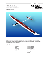
Aero-Maxx
Electric-powered RC
model aircraft
Order No. 1316/00
Specification
Wingspan: 1835 mm
Length: 1070 mm
All-up weight: approx. 900 - 1050 g
Motor: 600 size
Flight battery: 7 NiCd / NiMH cells,
or 3s-LiPo
“aero-naut” Modellbau
Stuttgarterstr. 18-22
D-72766 Reutlingen
Germany
http://www.aero-naut.de

Aero-Maxx
Aero-Maxx building instructions
2
The “Aero-Maxx” is a compact electric glider of all-wood construction, produced using modern CNC
technology. For ease of transport the wing is in two panels, joined by two steel rods for flying. The individual
model components are so accurately manufactured that everything fits perfectly. Very little building work is
required to complete the aeroplane.
Parts List
1.) Fuselage with factory-fitted snake outers, balsa / plywood construction, ready-built bare structure
2.) Inboard wing panels with factory-fitted joiner tubes, balsa / spruce construction, ready-built bare
structure
3.) Outboard wing panels, balsa spruce construction, ready-built bare structure
4.) Tailplane and elevators, balsa construction, ready-built bare structure
5.) Fin and rudder, balsa construction, ready-built bare structure
6.) Machined balsa tailskid, ready to fit
7.) Elevator and rudder pushrods, 0.8 mm spring steel wire, ready-made
8.) Wing retaining dowels, 4 mm Ø beech dowel
9.) Vacuum-moulded canopy, ready-made
10.) Two-part canopy baseplate, plywood, attached to the fuselage
11.) Plastic horns, ready-made
12.) Metal M2 pushrod connectors with washer and nut, ready-made
13.) Dummy pilot, unpainted styrofoam, ready-made
14.) Steel wing joiner rods, 5 mm Ø
15.) Decals and transfer film, ready-made
Accessories required to build the model
Building board (e.g. flat hardwood panel, 16 mm thick), balsa knife, ruler, imperial rule, white glue,
screwdriver, 5-minute epoxy, glasspaper, modelling pins, clothes pegs, masking tape, covering material.
Recommended RC equipment
1.) Two servos (each 13 - 20 g)
2.) Receiver (min. 4-channel)
Recommended electric power system
1.) “Actro C6” brushless motor, Order No. 7002/36
2.) “Actronic 45 bec” speed controller, Order No. 7002/51
3.) Folding propeller, 10 x 8”, Order No. 7234/32
4.) Spinner, 45 mm Ø
5.) Flight battery (e.g. 7 NiCd / NiMH cells or 3s LiPo)
The wing
• The wings are of classic built-up construction, and each wing panel consists of two parts. The two panels
should be glued together at the angle dictated by the facing ribs.
• Lay the inboard wing panels (with the built-in joiner tubes) flat on the building board and pin them down.
Slip a piece of clear plastic film under the outer ribs, to prevent the panels becoming glued to the building
board.
• Apply a thin coat of epoxy to the joint surface of the outboard wing panels, then push them against the
inboard panels and clamp the facing ribs together using clothes pegs. Check that the outboard panels are
not twisted relative to the inboard ones: the rib outlines must line up exactly. Carefully wipe away excess
epoxy which is squeezed out of the top of the joints.
• Allow the adhesive to cure fully (!), then remove the joined wing panels from the building board and slice
off any excess adhesive using a sharp knife.
• Carefully sand the joint areas smooth and flush.
The fuselage
• The basic fuselage structure is supplied ready-made; all you have to do is glue the tailplane and fin to it.
• Remove the elevators from the tailplane and place them to one side for the moment.
• Carefully slide the tailplane through the slot in the fuselage from one side. If it is too tight a fit, open up the
slot slightly using fine abrasive paper.
• Set the tailplane exactly central. Sight along the fuselage from the nose to check that the tailplane is
exactly horizontal. Take your time over this; it is better to check twice to be really sure.
• When you are satisfied, glue the tailplane to the fuselage using thin cyano-acrylate: apply small drops of
the adhesive to the joint areas of the fuselage, and allow them to run along the joints. Ensure that the cyano
really does run into all the contact areas.

Aero-Maxx
Aero-Maxx building instructions
3
• Remove the rudder from the fin, and place it to one side for the moment.
• Insert the fin in the appropriate slots in the top of the fuselage. If it is too tight, open up the slots carefully.
• Check that the fin is at right-angles to the tailplane.
• Glue the fin to the fuselage permanently, again using thin cyano. Apply the adhesive exactly as described
for the tailplane.
• Glue the tailskid to the underside of the fuselage.
• The control surfaces should not be attached again until the model has been covered.
The canopy
• The canopy is removable, to ensure that you can swap batteries quickly at the flying field. All you have to
do is glue the vacuum-moulded plastic canopy to the plywood plate. The canopy can then be held in place
using a strip of adhesive tape for ease of removal and re-fitting.
• First remove the two plywood parts from the fuselage, then cover the opening in the fuselage with clear
plastic film so that the canopy cannot become stuck to the fuselage.
• Glue the two plywood parts together on the fuselage, taking care to position them accurately.
• Carefully cut out the canopy, working along the marked lines. Don’t use large scissors for this; it is much
better to use nail scissors or special Lexan shears; these have curved blades and are available from most
model shops.
• Sand the cut edges smooth using fine glasspaper, and check that the canopy fits snugly and lines up
accurately with the fuselage shape. Take your time over this – a well-fitting canopy really looks good.
• The canopy can now be glued to the plywood frame using special plastic cement, although contact glue
can also be used (wet-on-wet). Tape the canopy to the fuselage until the glue has cured completely (!).
Covering
• We recommend translucent or solid-colour iron-on film for covering the model. If you have never used
iron-on film before, we recommend that you ask an experienced modeller to help you, otherwise you might
not obtain the results you wish.
• Sand the edges of the wingtips and all the edges of the tail surfaces to a rounded section. Use a sanding
block for this, clad with 180-grit abrasive paper or similar.
• Carefully remove all traces of dust from the model’s components. Take care to avoid distorting (warping)
the components when you apply the iron-on film.
• Apply the film following the instructions supplied by the manufacturer.
• We recommend that you use a darker colour on the outboard wing panels than on the centre section, as
the contrast will help you orientate the model in the air.
• The control surfaces can now be attached to the tailplane and fin using strips of adhesive tape as a hinge.
Ensure that they move freely to both sides of centre.
• Fit the hardwood dowels through the holes in the fuselage and glue them in place; they are used to secure
the wing retaining bands.
The motor
• The motor bulkhead is drilled to suit current 600-size electric motors. If you are using a brushed motor,
ensure that it is properly suppressed to prevent radio interference. The bulkhead is factory-installed at the
correct thrustline of 3° downthrust and 0° right sidethrust; these values have proved ideal over many test-
flights.
• Connect the motor to the speed controller, taking care to maintain correct polarity at the motor. Check the
direction of shaft rotation before you install the motor; drill a central hole in a small piece of wood and clamp
it on the motor shaft; this will help you detect the direction of rotation. Don’t use the propeller for this –
injury hazard!
• Screw the motor to the motor bulkhead. Tighten the screws firmly, but not to the point where they
compress and damage the wood.
• Assemble and install the folding propeller, hub and spinner following the instructions supplied by the
manufacturer.
The radio control system
• The servos should be installed in the rear of the compartment under the wing; the aperture in the servo
plate suits most current 13 g servos. Secure the servos with the screws and fittings supplied with them.
• The steel pushrods feature a Z-bend at one end; this should be at the tail end of the fuselage.
• Connect the horn to the steel rod first, then slip the pushrod into the snake outer sleeve from the tail end of
the fuselage, and glue the horn to the control surface exactly in line with the snake outer. The job is easier if
you first mark the horn position on the rudder and elevator using a ruler.

Aero-Maxx
Aero-Maxx building instructions
4
• Connect the steel pushrods to the servo output discs using the swivel pushrod connectors supplied. Check
that the connectors rotate smoothly.
• Place the receiver in the forward area of the compartment under the wing, right at the bottom of the
fuselage. Connect the servos and the speed controller to the receiver, then pack foam round it to hold it in
place. Be sure to read the installation instructions supplied by your RC system manufacturer.
• Assemble the model completely. Use four rubber bands to attach the wing to the fuselage: two crossed
over diagonally, two parallel to the fuselage sides.
• Check the model’s Centre of Gravity (balance point), and adjust the position of the flight battery if
necessary until it balances in the range 80 to 85 mm from the wing root leading edge. Fix the battery in
this position using Velcro tape.
The settings
• Switch the transmitter on first, and check that the throttle stick is at the “stop” position. Switch on the
receiver.
• Check the control functions: the rudder should move 30 mm to each side of centre when the stick is
moved. Set the elevator travel to 15 mm up and 10 mm down. Check, then check once more that the
controls work in the correct “sense”, i.e. left-stick really does produce left-rudder.
• Check the motor run. Caution: the spinning propeller represents an injury hazard!
The first flight
• If everything is in order, there is now nothing to stop you flying the model for the first time. If you are a
beginner, we urge you to join a local club and ask an experienced pilot for help. You are sure to find
somebody who will test-fly the aeroplane for you, and teach you the art of model flying step by step.
• However, it is also possible to try your luck on your own: wait for a day with little or no breeze, and give the
model a gentle launch with the wings level and the nose angled slightly above horizontal. Limit yourself
initially to correcting the angle of climb; don’t allow the model to slow down too much. If the model turns to
one side, apply opposite rudder to keep it flying straight.
• Once the model is at a safe height, switch the motor off and allow the machine to glide. Try operating the
controls, keeping all movements small and gradual initially. Don’t become over-confident too soon, and
always keep at a safe height – model flying is a skill which takes time to learn, just like driving a car or a
motorbike.
• Always land directly into wind. Allow the model to glide down with the motor switched off, and keep it flying
in a straight line towards the landing point. Apply gentle up-elevator just before it touches the ground. Avoid
using the rudder if possible when the aeroplane is very close to the ground.
Safety and hazard notes
• Model flying is a fascinating hobby. We recommend that you keep to the following basic guidelines
whenever you go flying, so that you do not annoy or endanger your fellow-man:
• You bear the responsibility for your actions and their consequences whenever you are flying a model
aircraft. For this reason it is essential to take out special model flying insurance. The best method of
obtaining this is to contact and join your national body (BMFA in Great Britain).
• In many countries it is only permissible to fly model aircraft using 35 MHz radio control equipment, but it is
your responsibility to find out if this applies where you live. You may need to register your RC equipment
with the authorities.
• Fly only at a site where you will not annoy or endanger anyone; the ideal place is an approved model
flying site.
• Never fly towards or over spectators, and never use other people as the target of dangerous or silly flight
manoeuvres.
• If your radio control equipment requires repair, have the work carried out by an expert. Interfering with the
equipment yourself will invalidate the official approval for your system.
• Do not switch your transmitter on until you have ensured that you will not cause interference to other radio
control systems in the vicinity. Don’t switch on if your system is on the same frequency as another set.
• Do join a model flying club, where you will find the answers to all your questions and solutions to your
modelling problems.
Please note: we will not consider any claim under guarantee for damage caused by ignoring these
instructions. We accept no liability for consequent damage which may result from any accident. It is
essential to observe the assembly instructions accurately when building and operating the model. The
building instructions include information relating to safe operation of the aeroplane. This model is by no
means a children’s plaything.
All of us at the Aero-Naut Modellbau team hope you have many hours of pleasure building and
flying your “Aero-Maxx”!
/