Page is loading ...

Twinspeedy / Sailspeedy
Sailspeedy / Twinspeedy instructions
1
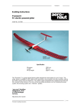
Building instructions
Twinspeedy
Order No. 1319/01
Sailspeedy
Order No. 1319/00
“aero-naut” Modellbau
Stuttgarterstr. 18-22
D-72766 Reutlingen
Germany
http://www.aero-naut.de
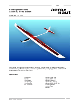
This model is of very simple construction, and can be built even by modellers with little prior
experience. All the parts contained in the kit are numbered, and the numbers are included in the text,
the stage photos and the parts list. It is important to complete the model in the sequence described in
these instructions, and to allow all glued joints to harden completely at the end of each stage before
resuming construction. We at “aero-naut” are unable to monitor the methods you use to build the
model, and for this reason “aero-naut” accepts no liability for damage or injury caused during
construction or operation of this model.
Flying this model successfully requires a basic knowledge of model flight. If you are a beginner please
ask an experienced model pilot to help you during the initial stages of learning to fly.
Use 5-minute epoxy for all joints.
Extra items required to complete the model
1 RC (radio control) system with V-tail mixer
4 9 g servos
1 Receiver battery
1 Clear adhesive tape, 10 - 20 mm wide
1 5-minute epoxy (two-pack resin adhesive)
1 Speed controller (for Twinspeedy only)
2 Race 400 6V motors, Order No. 7000/42, or Speed 400 6V (for Twinspeedy only)
2 Propellers (for Twinspeedy only), Order No. 7249/08
1 6-cell sub-C flight battery or 7-cell 4/5 sub-C flight battery (for Twinspeedy only)
Translation for following pictures:
6 Servokabel Servo lead
9 Schnitt Cut
14 Kohlefaserrohr Carbon fibre tube
Servoschacht Servo well
Tragflaeche Wing
Schnitt Cut
Querruder Aileron
Schlitz Slot
Schnitt Cut
18 Spinner cap

Twinspeedy / Sailspeedy
Sailspeedy / Twinspeedy instructions
2
Fuselage
The V-tail servos are mounted at the tail end of the fuselage,
and have to be extended to a length of 65 cm to reach the RC
system receiver, which is housed under the canopy at the front.
Please read the instructions supplied by your RC system and
servo manufacturer regarding extension leads, as suppressors
may be required.
Test the servos to ensure that they work correctly after they are
fitted with the extension leads. Wrap clear tape round the servo
leads for a distance of about 8 cm to protect them from the
epoxy. Glue the two servos in the tail of the fuselage (1), run the
leads through the hole in the fuselage (1) and allow them to
hang down (Fig. 1).
The next stage is to epoxy the carbon fibre tube (6) in the
fuselage (1) to stiffen and strengthen it.
Slip the carbon fibre tube (6) into the fuselage (1) from the canopy end and position it just short of the
servos at the tail end; the servo leads should be below the carbon fibre tube (6) (Fig. 2). Glue the
balsa plate (7) in the recess at the tail of the fuselage (1) to stiffen it. It should fit over the two servos
and the carbon fibre tube (6) (Fig. 3).
Run the servo leads forward into the cabin area (Fig. 6). Seal the underside of the fuselage by gluing
the balsa strip (12) in the channel; it should end flush with the outside skin of the fuselage.
Glue the sheet balsa doublers (8) in the front part of the fuselage (1) on both sides of the cockpit
recess (Figs. 4 + 6).
Three threaded nylon sleeves (13) have to be glued in the fuselage (1) to accept the wing retaining
screws: one on each side of the fuselage (1), where they are attached to the balsa doublers (8), and
the third in the circular recess at the rear of the wing saddle (Fig. 5). The balsa reinforcement (9) is
then glued on top of the third sleeve (13) (Fig. 6).
The two ring-screws (14) can now be glued between the sides of the fuselage (1) and the balsa
doublers (8): press the ring-screws (14) into the fuselage, then enlarge the holes and epoxy the ring-
screws securely to parts (1 + 8) (Fig. 7). These ring-screws are used to attach a rubber band (22)

Twinspeedy / Sailspeedy
Sailspeedy / Twinspeedy instructions
3
which engages in a third ring-screw in the canopy to hold it in place. Screw the third ring-screw into the
balsa reinforcement (2) and epoxy it to the inside of the canopy (19), after roughening the joint surface
with glasspaper. The ring-screws (14) should be positioned 110 mm aft of the front edge of the
canopy.
V-tail
The two V-tail panels (2 + 3) feature a channel on the underside. To
release the control surfaces cut from both ends of the channel (left
and right) to the trailing edge using a sharp knife, (Fig. 9).
The hinges are formed by two or three overlapping strips of
adhesive tape, applied along the top surface of the tail panel for the
full length of the channel (2 + 3). The tape must extend to a width of
12 mm on the fixed and moving panels.
Epoxy the two V-tail panels (2 + 3) together and glue the balsa
stiffener (10) in the recess on the underside (Fig. 10).
The next step is to glue the V-tail assembly to the tail end of the
fuselage. Cut a slot in the V-tail control surfaces (2 + 3) to accept
the GRP horns (16) (Fig. 11); the horns (16) must be parallel to the
servo output arms (Fig. 13). Roughen the joint surface of the horns
with glasspaper. Connect the short pushrod (17) to the servo output
arm and the GRP horn (16) (Fig. 12), and epoxy the horn in the
control surface. Take care to produce strong glued joints.
Wing
The first step here is to glue the carbon fibre tube (5) in the wing (4) to act as a spar. Sand the tube
lightly beforehand to obtain a strong joint, and remove all traces of dust (Fig. 14).
The servo leads must be extended to a length of 45 cm to reach the receiver, which will be installed in
the fuselage under the canopy. Check that the servos work correctly once the leads have been
extended.

Twinspeedy / Sailspeedy
Sailspeedy / Twinspeedy instructions
4
Connect the long pushrod (18) to the top end of the servo output
arm; you may need to open up the hole to 1.3 mm Ø, depending on
the servo. The servos can now be glued in the moulded-in recesses
in the wing.
Connect the horn (15) to the pushrod (18) before gluing the horn in
the slot. Sand the joint surfaces of the horn beforehand to obtain a
strong joint (Fig. 15).
Caution: take care not to allow epoxy to run between the wing and
the aileron, as the channel represents the aileron hinge line, and
must be kept free.
The aileron hinge takes the form of two or three overlapping strips of adhesive tape applied to the top
of the wing, over the aileron hinge line channel, joining the aileron to the wing. Note that the tape must
extend to a width of 12 mm onto the wing and aileron.
When the glued joints have set hard, release the ailerons from the wing by cutting from both ends of
the hinge line channel to the trailing edge of the wing (Fig. 14).
Run the servo leads along the carbon fibre tube (5) to the wing centre, and apply strips of wide
adhesive tape over the channels. Epoxy the sheet balsa discs (11) in the recesses in the top surface
of the wing (Fig. 16). They act as reinforcements for the wing screws used to secure the wing (4) to
the fuselage (1).
Twinspeedy
The wing of the Twinspeedy features two moulded-in fairings into
which the electric motors are glued from the underside. Before
installing the motors the power supply leads must be soldered to the
terminals. If the motors do not feature factory-fitted suppressors,
three ceramic capacitors must be soldered to each motor at this
stage:
• Between the positive and negative terminals on the motor;
• From the positive motor terminal to the motor can;
• From the negative motor terminal to the motor can.
Lay the motor power cables in the channel and run them to the
centre of the wing. Cover the channel with a strip of wide adhesive
tape (Fig. 17).
The propeller, Order No. 7249/08, is designed for tractor use as standard and must be converted to
pusher orientation. Pull off the spinner cap (Fig. 18), turn the propeller through 180° and push the
spinner cap back into place. The inscription should now be on the exposed face (Fig. 19). Press the
propellers onto the motor shafts as far as they will go; ensure that the inscribed face now faces the V-
tail (Fig. 20).
Final assembly
The receiving system and battery are installed in the area under the canopy in the following sequence,
working from front to rear:
• Flight battery (Twinspeedy only)
• Speed controller (Twinspeedy only)
• Receiver battery
• Receiver

Twinspeedy / Sailspeedy
Sailspeedy / Twinspeedy instructions
5
Run the receiver aerial along the fuselage under the wing and to the V-tail, and fix it to the fuselage
with several strips of adhesive tape. Don’t run the aerial through the V-tail, as it could become jammed
in the control surfaces; instead allow it to trail freely from a point just in front of the tail.
Connect the RC system and speed controller as described in the instructions supplied with these
items.
All control surfaces should be set to 10 mm deflections on both sides of neutral (centre).
Centre of Gravity
The model must be balanced correctly if it is to fly properly. The Centre of Gravity (CG) should be at
the position of the carbon fibre tube (5) fitted in the underside of the wing. Adjust the position of the
system components inside the fuselage until the model balances at the stated point. If this is not
possible, ballast must be fitted at the nose or tail as required. To check the CG fix the wing (4) to the
fuselage (1) using the nylon screws (21) and support the model at the stated point under the wing
roots on two fingertips. When correctly balanced the model will hang level, with the nose slightly down.
Parts list
No. Part Material No. off Size
1 Fuselage High-density foam 1 Ready made
2 V-tail panel, right High-density foam 1 Ready made
3 V-tail panel, left High-density foam 1 Ready made
4 Wing High-density foam 1 Ready made
5 Wing spar Carbon fibre tube 1 748 x 4.9 Ø mm
6 Fuselage stiffener Carbon fibre tube 1 465 x 4.9 Ø mm
7 Fuselage stiffener Balsa 1 110 x 15 x 2.5 mm
8 Fuselage doubler Balsa 2 327 x 55 x 2.5 mm
9 Fuselage reinforcement Balsa 1 25 x 22 x 2.5 mm
10 V-tail stiffener Balsa 1 80 x 10 x 2.5 mm
11 Wing screw reinforcement Balsa 3 12 Ø x 2.5 mm
12 Fuselage sealing strip Balsa strip 1 415 x 5 x 5 mm
13 Threaded sleeve Nylon 3 M4 Order No. 7329/64
14 Ring-screw Metal 3 Order No. 7800/00
15 Control surface horn Plastic 2 Order No. 7491/01
16 Control surface horn GRP 2 Order No. 7491/11
17 Short pushrod Steel rod 2 Ready made, 45 mm
18 Long pushrod Mild steel rod 2 Ready made, 81 mm
19 Canopy Plastic 1 Ready made
20 Reinforcement Balsa 1 10 x 10 x 30 mm
21 Screw Nylon 3 M4 Order No. 7769/04
22 Rubber band Rubber 1 Order No.
23 Decal sheet Self-adhesive film 1
24 Instructions 1
25 Abrasive paper 1
+
8
8
9
7
11
10
/