Page is loading ...

INSTALLATION AND PROGRAMMING GUIDE
9000 Series Wireless Keypads


TABLE OF CONTENTS
About the Keypad ...................................... 1
What is Included ................................................... 1
Keypad Features ......................................... 2
Enter Characters .........................................3
Enter Alpha Characters ..................................... 3
Enter Non-Alphanumeric Characters .......... 3
System Components ..................................4
Card Reader...........................................................4
2-Button Panic Keys ........................................... 4
Internal Speaker Operation ............................. 4
Backlighting ........................................................... 5
Backlit Logo .......................................................... 5
User Options Menu ............................................. 6
Program the Keypad ..................................7
Install the Keypad .......................................9
Remove the Cover ............................................... 9
Mount the Keypad ..............................................10
Power the Keypad ............................................... 11
Program the Keypad Options ................. 12
Keypad Options .................................................. 12
Custom Card Format ................................ 14
Additional Programming (9063 only) ........21
Test the Keypad ........................................22
End User Training .................................... 24
Keypad Arming and Disarming .................... 25
Keypad Entry Delay .......................................... 27
Replace the Battery ..........................................28
Public Card Formats ................................ 31
Readers and Credentials .........................32
Ordering Information .............................. 34
Keypads .................................................................34
Accessories ..........................................................35
Batteries ................................................................ 35


Digital Monitoring Products, Inc | 9000 Series Installation and Programming Guide 1
ABOUT THE KEYPAD
The 9060 and 9063 are fully functioning supervised wireless keypads. The wireless
keypads provide installation flexibility while also oering codeless arming and disarming
capabilities.
Each keypad provides:
• Custom 32-character full LCD display
• Three 2-button panic keys
• Backlit keyboard with easy-to-read lettering
• Internal speaker
• Wall tamper protection
• Keyboard backlighting that turns red in alarm conditions
• Wireless Encryption (Keypad Version 300 and higher, Panel Version 183 and higher)
The 9063 keypad also provides a built-in proximity card reader designed to read proximity
credentials for codeless arming and disarming.
What is Included
• One wireless keypad mounted in a Thinline™ two-part housing (base and cover)
• One internal rechargeable 3.7V lithium battery
• One 12VDC DC Plug-in Power Supply
• Built-in proximity card reader (9063 only)

9000 Series Installation and Programming Guide | Digital Monitoring Products, Inc. 2
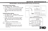
KEYPAD FEATURES
Keypad Display/
Status List
Select Keys
Panic Keys
Command
(CMD) Key
Back Arrow Key
1
4
3
2
Figure 1: 9000 Series LCD Keypad
1. Backlit Logo
2. Proximity
Credential
Reader
(9063 only)

Digital Monitoring Products, Inc | 9000 Series Installation and Programming Guide 3
ENTER CHARACTERS
Enter Alpha Characters
To enter an alpha character, press the number
key that has the desired letter below it. The
keypad display shows the number on that key.
To change the number to a letter, press the top
row select key that corresponds to the letter
location under the key. See Figure 2.
Enter Non-Alphanumeric
Characters
Each key has a non-alpha special character that
is not shown on the keypad. Non-alphanumeric
characters are entered into the keypad the same
way as alphanumeric characters. See Figure 3.
First Letter
Second Letter
Third Letter
Special Character
(CBA
Figure 2: Entering Alpha Characters
1 2 3 4
9 0 CMD
5 6 7 8
A
(
C
B
D
)
F
E
G
!
I
H
J
?
L
K
V
,
X
W
S
$
U
T
P
&
R
Q
M
/
O
N
Y
'
(space)
Z
-
#
*
.
Figure 3: Keys with Non-Alpha
Characters

9000 Series Installation and Programming Guide | Digital Monitoring Products, Inc. 4
SYSTEM COMPONENTS
Card Reader
When a proximity credential is presented to the 9063 internal reader, located behind
the backlit logo, a beep tone is emitted to provide an audible acknowledgment of the
credential read.
2-Button Panic Keys
All keypads oer a panic key function that allows users to send panic, emergency, or fire
reports to the central station in an emergency. Enable the panic key function in the keypad
user menu. Place the supplied icon stickers below the top row select keys. The user must
press and hold the two select keys for two seconds until a beep is heard.
Panic (left two select keys)—Zone 19 + Device Address
Emergency Non-Medical (center two select keys)—Zone 29 + Device Address
Fire (right two select keys)—Zone 39 + Device Address
Internal Speaker Operation
All keypads emit standard tones for key presses, entry delay, and system alerts. The
speaker also provides distinct burglary, fire, zone monitor, and prewarn cadences. The
keypads provide an alternate prewarn with alarm cadence that occurs when the status list
displays a zone alarm.

Digital Monitoring Products, Inc | 9000 Series Installation and Programming Guide 5
Backlighting
The keyboard lights when a key is pressed or the speaker sounds. During an alarm
condition, the keyboard lighted area turns red. When all alarm conditions are cleared from
the display, the red display turns o and the lighted area returns to the user-selected
brightness.
Backlit Logo
The backlit logo indicates the armed status of the panel and the power and battery status
of the keypad. Depending on the status, the LED displays in Red or Green. See Table 1
COLOR AND
ACTIVITY
ARMED STATUS KEYPAD POWER STATUS
Green Steady Panel Disarmed Primary Power OK, Battery OK
Green Blinking Panel Disarmed Primary Power OK, Battery Fault
No Light Panel Disarmed Primary Power Fault, Battery OK
Red Steady Panel Armed Primary Power OK, Battery OK
Red/Green Alternate Panel Armed Primary Power OK, Battery Fault
Red Blinking Panel Armed Primary Power Fault, Battery OK
Table 1: Backlit Logo

9000 Series Installation and Programming Guide | Digital Monitoring Products, Inc. 6
User Options Menu
To access the Options menu, press and hold the back arrow and CMD keys for 2seconds.
Backlighting Brightness
Adjust the brightness, power and armed LEDs, green keyboard, and logo backlighting. At
SET BRIGHTNESS, use the left and right select keys to adjust the brightness. The
brightness reverts to maximum intensity whenever a key is pressed. If no keys are pressed
and the speaker has not sounded for 10seconds, the user-selected brightness restores.
Note: During primary power loss, the backlighting turns completely o after
10seconds of no activity to conserve the standby battery.
Internal Speaker Tone
Adjust the keypad internal speaker tone. At SET TONE, use the left and right select keys to
decrease and increase the tone.
Internal Volume Level
Adjust the keypad internal speaker volume for key presses and entry delay tone
conditions. During alarm and trouble conditions, the volume is always at maximum level.
At SET VOLUME LEVEL, use the left and right select keys to adjust the volume.
Model Number
Display the keypad model number, firmware version, and date.
Serial Number Display
Display the keypad serial number.

Digital Monitoring Products, Inc | 9000 Series Installation and Programming Guide 7
PROGRAM THE KEYPAD
The keypads can be programmed into the control panel by entering the serial number
in Device Setup or using the wireless keypad association operation. A maximum of
4keypads may be used with the XT30/XT50 panel, 7keypads with XR150/XR550 panels
using Version 191 software or higher, and 7keypads with XTLplus/XTLtouch panels.
Device Setup Programming
Program the keypad as a device in Device Setup during panel programming. At the serial
number prompt, enter the 8-digit serial number. Continue to program the device as
directed in the panel programming guide.
Note: If the keypad serial number is entered manually, the Wireless Keypad
Association operation is not required.
Wireless Keypad Association
Enable Wireless Keypad Association operation on both the keypad and panel.
To enable association operation in the keypad, access the Installer Options Menu and
select RF Survey. The keypad logo LEDs turn red until association is successful.
To enable association operation in XR150/XR550, XT30/XT50, and XTLplus/XTLtouch
panels, reset the panel 3times within 12seconds. Allow the keypad bus Transmit/Receive
LEDs to turn back on between each reset.

9000 Series Installation and Programming Guide | Digital Monitoring Products, Inc. 8
For 60seconds, the panel listens for wireless keypads that are in the Installer Options
Menu and have not been programmed, or associated into another panel. Those keypads
are assigned to the first open device position automatically based upon the order in which
they are detected. The keypad logo turns green to indicate it has been associated with the
panel.
Selecting the Proper Location
9000 Series keypads provide a built-in survey capability in the Installer Options menu to
allow one person to confirm keypad communication with the panel. For more information,
see “Keypad Wireless Survey”.

Digital Monitoring Products, Inc | 9000 Series Installation and Programming Guide 9
INSTALL THE KEYPAD
Remove the Cover
The keypad housing is made up of two parts: the cover,
which contains the circuit board and components, and
the base.
To separate the keypad cover from the base, insert a
flathead screwdriver into one of the slots on the bottom
of the keypad and gently lift the screwdriver upward.
Repeat with the other slot. Gently separate the cover
from the base and set the cover containing the keypad
components aside. See Figure 4
1
Figure 4: Separate the
Keypad Housing
Cover
Base
All DMP keypad housings are designed to easily install
on any desk stand, 4” plastic square box, 3-gang plastic
switch box, or a flat surface. Do not install the keypad near
any metal objects.

9000 Series Installation and Programming Guide | Digital Monitoring Products, Inc. 10
Mount the Keypad
Secure the keypad to the wall ensuring that the wall tamper switch makes proper
contact with the wall. Use the supplied screws in the mounting hole locations. See
Figure 5.
2
Black (-)
Black/White
stripe (+)
Wall
Tamper
Surface and Backbox Mounting Holes
Surface and Backbox Mounting Holes
Combined 4-Square and
3-Gang Switch Box
Mounting Holes
Figure 5: Mounting Holes on Keypad Back

Digital Monitoring Products, Inc | 9000 Series Installation and Programming Guide 11
Power the Keypad
Primary DC Power Supply
Locate the keypad near a wall outlet to allow connection of the Model 371-500
plug-in DC power supply. See Figure 6 for a diagram of the DC power supply
connector. In addition to powering the keypad, the power supply also charges the
internal back-up battery. The plug-in power supply includes a six foot cord. The
cord can be lengthened but should be located within 100feet of the keypad using
22AWG wire.
Caution: Observe polarity when extending
the power supply cord.
When the power supply connector is plugged
into the keypad, the internal battery is
automatically connected. The keypad can
operate from battery only as long as the power
supply connector is plugged into the keypad.
Standby Battery
The keypad rechargeable battery provides 24hours of backup battery power
when primary DC power is unavailable. It is shipped already installed inside the
keypad. The battery is intended for backup power only and not to operate the
keypad on a daily basis. If the battery is low, or not plugged into the internal
battery connector, a low battery condition is indicated by the panel when the
battery falls below 3.62VDC. To restore the keypad from a low battery state, the
voltage must be above 3.62 VDC.
3
Black (-)
Black/White
Stripe (+)
Figure 6: DC Power Supply
Connector

9000 Series Installation and Programming Guide | Digital Monitoring Products, Inc. 12
PROGRAM THE KEYPAD OPTIONS
Keypad Options and Keypad Diagnostic menus allow install and service technicians to
configure and test keypad operation. To access the installer options:
Hold down the back arrow and CMD keys for two seconds. Enter 3577 (INST) and press
CMD.
The display changes to KPD OPT (keypad options), KPD DIAG (keypad diagnostics),
KPD RF (wireless survey), and STOP.
The Keypad Options menu allows you to set the default keypad message, enable 2-button
Panic keys, and additional options.
The keypad must be operating anywhere in the Installer Options menu, 3577 (INST), to
be automatically associated by the control panel receiver. To place the keypad into the
association operation, first remove the power connector from the back of the keypad.
Then reapply power and access the Installer Options menu. See “Keypad Wireless Survey”
for more information.
Keypad Options
Keypad Options
To program keypad options, press KPD OPT.
Serial Number
The keypad displays the serial number of the keypad.
KPD KPD KPD
OPT DIAG RF STOP
SERIAL #:XXXXXXXX

Digital Monitoring Products, Inc | 9000 Series Installation and Programming Guide 13
Default Keypad Message
Enter a custom message of up to 16characters to appear at
the top of the keypad display. Press any select key, enter a new
message, and press CMD.
Arm Panic Keys
Use this option to configure the select keys as two-button
panic keys. To enable or disable a panic option, press
the select key under the desired name: PN (panic), EM
(emergency), and FI (fire). Press the select key again to disable
the panic option. Once the panic option is enabled, an asterisk
displays next to the selected option(s).
ALL? NO YES (9063 only)
Select the number of seconds (1-9) the keypad should
wait when an area system displays ALL? NO YES during
arming/disarming or a HOME/SLEEP/AWAY system waits
during arming only. If NO or YES, or HOME, SLEEP, or AWAY
is not manually selected before the delay expires, the keypad
automatically selects YES or AWAY. Select zero (0) to disable
this feature. The delay also occurs when any credential is
presented for arming the Home/Sleep/Away system. Default
is 2.
Enable Tamper?
Select YES to enable wall tamper protection. Default is NO.
DEFAULT KPD MSG:
ARM PANIC KEYS:
*PN *EM *FI
ALL?: NO YES
DELAY: 2
ENABLE TAMPER?
NO YES

9000 Series Installation and Programming Guide | Digital Monitoring Products, Inc. 14
Card Formats
Select DMP to allow credentials that use a 26-45bit data
string. The menu advances to REQUIRE SITE.
Select CUSTOM to disable DMP format and program slots 1-8
as needed. The menu advances to FORMAT NO.
Select ANY to allow all Wiegand card reads to activate the
door strike relay. The door strike relay is activated for the
length of time programmed in ZN3 REX TIME. No user code
information is sent to the panel. The menu advances to NO
COMM WITH PNL.
The default card format is DMP.
CARD FORMATS
DMP CUSTOM ANY
CUSTOM CARD FORMAT

Digital Monitoring Products, Inc | 9000 Series Installation and Programming Guide 15
Card Format Number
Select the slot number (1-8) that you want to program for a
custom non-DMP card format. The format that is programmed
into slot 1 is the default format. In the event that a card with
an unrecognized format is used, that card will be read in the
format that is programmed in slot 1. To restrict card reads to
specific formats, only program slots 2-8.
See Public Card Formats for some publicly available card
formats that can be used with the keypad. Other private or
custom formats may also be compatible. Please contact the
credential supplier or manufacturer for the bit structure.
Note: If you select slot 1 and you are upgrading from
XRpanel version 182 or earlier, FORMAT NAME will
automatically be named SINGLE CARD FORMAT and
WIEGAND CODE LENGTH will default to 45.
Format Name
Press any select area to rename the card format. Press CMD to
save and advance.
CARD FORMATS
FORMAT NO: -
FORMAT NAME
*UNUSED*

9000 Series Installation and Programming Guide | Digital Monitoring Products, Inc. 16
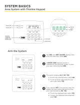
Wiegand Code Length
When using a custom credential, enter the total number of bits
to be received in Wiegand code including parity bits.
Press any select key or area to enter a number between
1-255to equal the number of bits. Default is 26bits.
An access card contains data bits for a site code, user code,
and start/stop/parity bits. The starting position, location, and
code length must be determined and programmed into the
keypad. See Figure 7.
WIEGAND CODE
LENGTH: 26
01110101101101010001100111
First Bit
Received
Position = 0
Site Code
Position = 1
Length = 8
User Code
Position = 9
Length = 16
Last Bit
Received
Position = 25
In this example the Wiegand Code Length = 26 bits.
Figure 7: Wiegand Data Stream Bit Location
/