Page is loading ...

Repair Manual
Americas Business Center
Technical Services
201 Burlington Road
Bedford MA 01730
TEL: 1.781.386.5309
FAX: 1.781.386.5988
Miniportrait 204/404
May 1997

Repair Manual Model 204/404 MiniPortrait Camera
2
Contents
Purpose of this Manual..................................... 3
Organization of this Manual.............................. 3
Other Documents Required for Repair............. 3
List of Illustrations............................................. 4
1. Description and Operation .......................... 5
2. Troubleshooting .......................................... 23
3. Parts Replacement...................................... 34
4. Schematics.................................................. 57
About this Manual
This manual applies to both the Model 204 and 404 cameras. Differences
between these two models will be noted throughout the document.

Repair Manual Model 204/404 MiniPortrait Camera
3
Purpose of this Manual
This manual is intended as a reference guide for Polaroid and Polaroid
authorized technical personnel repairing the Polaroid Model 204/404
MiniPortrait Camera.
Organization of this Repair Manual
Description and Operation. General information about camera features,
capabilities, applications and operating instructions.
Troubleshooting. Function tables for diagnosing problems.
Parts Replacement. Step-by-step procedures for replacing system assemblies
and components.
Schematics. Electronic schematics to isolate problems and assist in component
replacement.
Other Documents Required for Repair
In addition to this manual, repair requires the use of the Polaroid Model 204/404
MiniPortrait Camera Parts Catalog.

Repair Manual Model 204/404 MiniPortrait Camera
4
List of Illustrations
Section 1. Description and Operation
Figure 1-1 Rear (Operational) View .......................................................................8
Figure 1-2 Front View ............................................................................................8
Section 3. Parts Replacement
Figure 3-1 Removing the Front/Rear Housing .......................................................36
Figure 3-2 Unplugging the Electrical Connectors ..................................................37
Figure 3-3 Replacing the Aiming Light....................................................................40
Figure 3-4 Adjusting the Aiming Light.....................................................................40
Figure 3-5 Replacing the Strobe Assembly ............................................................41
Figure 3-6 Removing the Shutter Assembly............................................................42
Figure 3-7 Replacing the Solenoid(s).....................................................................44
Figure 3-8 Solenoid/Shutter Blade Orientation ......................................................45
Figure 3-9 Removing the Baffle .............................................................................47
Figure 3-10 Removing the Pull Film Switch ...........................................................47
Figure 3-11 Checking Switch Position with Go/No-Go Gauge................................48
Figure 3-12 Replacing the Load Film Sensor ........................................................50
Figure 3-13 Logic Board Screws and Connectors .................................................52
Figure 3-14 Power Board Screws and Connectors.................................................54
Figure 3-15 LCD Display Board Removal...............................................................55
Figure 3-16 Replacing the Capacitor......................................................................56
Section 4. Schematics
Logic Board.............................................................................................................58
Power Board ...........................................................................................................59
Harness Diagram....................................................................................................60

Repair Manual Model 204/404 MiniPortrait Camera
5
Section 1. Description and Operation
Important Safety Instructions ................................................................................6
A. General Description..........................................................................................7
B. Camera Components........................................................................................8
C. Camera Features............................................................................................10
D. Operating Instructions....................................................................................13
(1) Work area requirements...........................................................................13
(2) Preparing the camera for making ID photos.............................................13
(3) Making ID photos .....................................................................................16
(4) Programming the camera.........................................................................19

Repair Manual Model 204/404 MiniPortrait Camera
6
Important Safety Instructions
When using the camera, always follow these basic safety precautions:
• Read and understand all instructions before setting up and using the system.
• Close supervision is necessary when any appliance is used by or near
children. Do not leave the camera unattended while in use.
• Do not operate the camera with a damaged cord, or when it has been
dropped or damaged, until it has been examined by a qualified service
person.
• Position the cord so that it will not be tripped over, pulled, or in contact with
hot or sharp surfaces.
• If an extension cord is necessary, a UL recognized grounded cord with a
rating at least equal to that of the camera should be used.
• Always turn the camera OFF before unplugging.
• Always unplug the camera from the electrical outlet when not in use, and
before cleaning and servicing. Never pull the cord from the outlet. Grasp
and pull the cord from the outlet to disconnect.
• To reduce the risk of electrical shock, do not immerse the camera in water or
other liquids and do not operate outdoors in inclement weather.
CAUTION
The film used by this camera contains a caustic jelly that is safely
packed inside the film pack. If you should accidentally get some of
this jelly on your skin, wipe it off immediately and wash the area with
plenty of water as soon as possible. Under all circumstances, keep
the jelly away from the mouth and eyes. Keep discarded materials
out of reach of children and animals, and out of contact with clothing
and furniture, as discarded materials still contain caustic jelly
residue.

Repair Manual Model 204/404 MiniPortrait Camera
7
A. General Description
The Polaroid Model 204/404 MiniPortrait Camera is a new, optical cut-and-paste
camera that features the unique combination of programmability, low cost, and
exceptional ease-of-use.
Features include programmable LCD graphic display of step-by-step operational
prompts, power-on memory, battery capability, counters for strobe flashes and
packs used, key switch, tripod mount, converging light rangefinder, sync circuit
system with ON/OFF switch, and removable film holder for black-and-white and
color films.
The system consists of a camera head, camera base and AC/DC adapter. The
camera head pivots so that it can swing down into the camera base for storage
and transport, and swing up for picture-taking.
The camera can be positioned either 40 inches from the subject for a larger
head size, or 60 inches from the subject for a smaller head size. At 60 inches, a
supplementary lens is required for proper focus.

Repair Manual Model 204/404 MiniPortrait Camera
8
B. Camera Components
Refer to these illustrations as you proceed through the following sections:
Preparing the camera for making ID photos, Making ID photos, and
Programming the camera.
40 60 4060
I
A
C
BQ
E
D
F
G
H
K
L
M
G
N
O
P
I
J
0
R
Caution
Attention
Polaroid
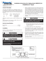
Figure 1-1 Rear (Operational) View
T
UU
V
S
Polaroid
Figure 1-2 Front View

Repair Manual Model 204/404 MiniPortrait Camera
9
Rear View Callouts
Call-out Component
A Display Screen
B Program/Power Button
C Shutter Button
D UP Cursor Symbol
E Menu Symbol
F Camera Back
G Aim Light Adjustment Lever
H Camera ON/OFF Switch
I Release Knob
J Locking Knob
K Strobe Switch
L Flash Sync Socket
M Power Cord Socket
N DOWN Cursor Symbol
O EXIT PROGRAM Cursor
Symbol
P Aiming Button
Q Brightener Button
R Dark Slide
Front View Callouts
S Strobe
T Lenses
U Aim Lights
V Aperture Adjustment

Repair Manual Model 204/404 MiniPortrait Camera
10
C. Camera Features
Picture version
There are two camera versions. The Model 204
makes 2 images per film frame; the Model 404
makes 4 images per film frame. Both use Type
669 film.
Totally programmable
Allows operator to program all functions needed
for operation of ID program.
Graphic display
Display guides operator through all
programming and operating functions.
Voltages
AC/DC adapter operates on 115 or 90 - 250-volt
wall unit.
Battery capability
Operates on 12-volt battery supply.
Low power indicator
A low battery icon will appear on the graphic
display and an audio beep will inform the
operator of need to charge or replace battery.
Low battery protection
Automatically shuts down if low battery indicator
is ignored, preventing damage to the camera’s
microprocessor.
Variable aperture
Adjustable aperture for different film speeds.
Variable exposure
Programmable strobe brightness setting for
exposure in all lighting conditions.
Strobe boost
Strobe boost (brightener) button will enhance
brightness by 1/2 stop for one picture without
changing exposure setting.
Strobe count
Counts all strobe flashes. The number will be
displayed in Program Mode; used for tracking
the number of photos produced.
Pack count
Counts the number of film packs used. Used for
determining/controlling film usage.
Out of film sensor
Sensor alerts the operator when camera is out
of film.

Repair Manual Model 204/404 MiniPortrait Camera
11
Language
Camera display can be programmed to read in
English, Spanish, French, or Italian. Language
can be customized for large volumes.
Development time
Development time can be programmed from
thirty (30) seconds to one hundred and ninety
(190) seconds to accommodate all types of film.
Select capability
Allows the operator to select:
One or two subjects with the 204 camera
One, two or four subjects with 404 camera
Timer
Built-in timer will timeout after the film is pulled;
audible beeps signal the operator when the film
is fully developed.
Memory
If the camera is turned off during picture-taking,
the existing sequence continues when turned on
again. By not resetting, film waste is prevented.
Auto shut off
Camera can be programmed to do the following:
1) Shut off automatically if unused for 10
minutes, or 2) Shut off automatically if unused
for 20 minutes, or 3) Remain on until camera
power is turned off.
Converging lights
viewfinder/rangefinder
Converging flashing light beams allow the
operator to set the proper camera-to-subject
distance, and center the subject in the photo.
Key switch
Allows power to be turned on or off without
unplugging the camera. Key can be removed to
prevent unauthorized use.
Tripod mount
With insert adapter: Standard 1/4-20 screw
mount for desk stand or tripod.
With adapter removed: 3/8-16 screw mount.

Repair Manual Model 204/404 MiniPortrait Camera
12
Electronic sync with ON -
OFF switch
PC type external X sync connector. Design
allows use of auxiliary flash strobe with option of
turning camera flash strobe ON or OFF.
Removable camera back
Dedicated interchangeable camera back (with
removable dark slide).

Repair Manual Model 204/404 MiniPortrait Camera
13
D. Operating Instructions
(1) Work area requirements
• Work area of at least 8 x 10 feet; avoid exposure to extreme temperatures
(avoid doors, windows, etc.).
• Table to support camera; 29 - 30 inches (76 cm) high.
• Electrical outlet (ground where applicable).
• Wastebasket.
• Non-reflective (felt or velvet) backdrop to place behind subject; backdrop
should be at least 30 inches (76 cm) square.
• Chair for subject to sit in; should be 17 - 18 inches (45 cm) high.
(2) Preparing the camera for making ID photos
Note: Throughout this section, component names are followed by a letter in parenthesis. This
letter refers to the component location as depicted in Figures 1-1 and 1-2.
1. Place the camera on the table.
2. Pull out the silver release knob (I) on the
side of the camera base, and while holding it
out, grasp the camera head firmly and swing
it into the upright position. The knob will
click in when the camera is fully upright.
Note: The camera is pivoted to the lower position for
storage and transport.
40 60 4060
I
I
0
3. Tighten the black locking knob (J) under the
camera to prevent it from moving on the
camera base.
Note: If for any reason it is necessary to remove the
camera from the base, unscrew the black knob
completely.
40 60 4060
I
J
0
4. Place the backdrop on the wall and position
a chair in front of the backdrop.

Repair Manual Model 204/404 MiniPortrait Camera
14
5. Adjust the camera-to-subject distance.
Place a subject in the chair and measure 40
inches from the camera lenses to the
subject’s chin. This may be approximate
since the final rangefinder adjustment is
made with the aiming lights during picture-
taking.
Note: For distances of 60 inches, adjustments can be
made during picture-taking by simply moving the
camera back 20 inches and making final adjustments
with the aiming lights.
6. Plug one end of the AC Adapter into the
power cord socket (M) of the camera and the
other end into the power source. Or, use the
optional 12 volt battery.
40 60 4060
I
0
M
7. Power up the camera by turning the key (H)
clockwise 90° to the ON position (shown by
arrow). Make sure the AC outlet is
grounded.
I
0
H
8. Adjust the aperture (V) for the recommended
f/stop setting. Refer to table at right.
f . . . . . .
11
44
32
22
16
64
Film Speed Aperture
ASA 80 f/11-1/2
ASA 100 f/11-1/2
ASA 125 f/16
ASA 3000 f/64

Repair Manual Model 204/404 MiniPortrait Camera
15
9. Set the Aim Light Adjustment Lever (G) for
the proper camera to subject distance; 40
inches for larger image or 60 inches for
smaller image size.
Note: Photos taken at 60 inches require a special
accessory lens.
40 60 4060
I
GG
0
10. Turn the Strobe Switch (K) to the ON (up)
position.
Note: If using an auxiliary flash, turn the Strobe Switch
to the OFF (down) position; plug the flash into the
Flash Sync Socket (L) of the camera.
40 60 4060
I
K
L
G
0
11. Remove the camera’s dark slide (R)
R

Repair Manual Model 204/404 MiniPortrait Camera
16
(3) Making ID photos
1. Power up the camera by turning the key (H)
clockwise 90° (as shown by arrow).
A LOAD FILM message appears in the
Display Screen (A).
I
0
H
LOAD FILM
2. Load the film into the Camera Back (F).
A PULL FILM message appears in the
Display Screen. Also, a “1” (indicating first
film frame) is visible in the upper left corner.
Note: If a partially used film pack is inserted, a
READY message is displayed.
PULL FILM
1
3. Pull the film safety cover; a white tab will be
visible.
A READY message appears in the Display
Screen and the first image blinks.
Note: The imaging format for each frame depends on
the PICTURE SELECT menu explained in the next
section. For example, four different images, four
identical images, or, two double images.
READY
Blinking
1
4. Prior to taking ID photos, access the
Program Mode to make appropriate camera
adjustments. Begin by pressing the
Program/Power Button (B).
B

Repair Manual Model 204/404 MiniPortrait Camera
17
4. Continued
The program menu (at right) will appear.
Note: For details about each adjustment screen, refer
to the next section, “Programming the camera”.
COUNTS
EXPOSURE FILM
PICTURE SELECT 000380
DEVELOPMENT TIME
RESET COUNTS STROBE
LANGUAGE 001139
AUTO SHUT OFF
EXIT
5. Check to make sure the camera aperture is
set according to the film type being used.
Film Film Speed Aperture
T669 ASA 80 f/11 1/2
T100 ASA 100 f/11 1/2
T667 ASA 3000 f/64
6. Aim the camera as follows:
Press the Aiming Button (P) and the Aiming
Light will come on; it will blink for
approximately 15 seconds. Center the
converging light spots on the subject’s chin
for proper framing.
Note: Once the Aiming Light goes out, the Shutter
Button is deactivated and a picture cannot be taken
until the Aiming Light Button is pressed again.
P
Converging light
beams
7. Press the Shutter Button (C) to take the
picture.
While the strobe is recharging, a WAIT
message is displayed.
A READY message informs the operator that
the second picture on the frame can now be
taken. Also, the next image blinks.
C
WAIT
1
READY
Blinking
1

Repair Manual Model 204/404 MiniPortrait Camera
18
7. Continued
Continue taking pictures until each photo on
the frame is taken.
When all photos are taken, a PULL FILM
message appears and all four image boxes
are solid.
Note: If the subject has a dark complexion, more
illumination can be provided by pressing the
Brightener Button (Q) just prior to taking the photo. It
is activated for one photo only.
A starburst (shown at right) informs the operator that
the Image Brightener is activated for that photo.
PULL FILM
1
Q
READY
1
8. Pull the film from the camera; first the white
tab, then the yellow tab. A READY message
is displayed. Also, a “2” (indicating the
second frame about to be taken) appears in
the upper left corner.
Lay the picture frame on a flat surface while
developing. Audible beeps will signal when
development is complete.
After development, separate the print from
the negative.
READY
1 2
Blinking
Blinking

Repair Manual Model 204/404 MiniPortrait Camera
19
(4) Programming the camera
This section describes the process for accessing the Program Mode and making
the required adjustments prior to picture-taking.
Important: The Display Screen must read READY or LOAD FILM in order to access the Program
Mode (refer to item 4. in the previous section, “Making ID photos”).
1. Press the Program/Power Button (B)...
... and the program menu (at right) will be
displayed. This initial screen highlights
COUNTS, which shows the number of film
frames that have been pulled, and the
number of strobe firings. No adjustments are
made in this screen.
Note: You can scroll and select any item on the menu
by pressing and holding the Program/Power Button;
the selection will be made upon releasing the button.
B
COUNTS
EXPOSURE FILM
PICTURE SELECT 000380
DEVELOPMENT TIME
RESET COUNTS STROBE
LANGUAGE 001139
AUTO SHUT OFF
EXIT
2. Press the Program/Power Button (B) a
second time and the EXPOSURE adjustment
screen is displayed. A range of seven
exposure settings can be selected.
To decrease exposure, repeatedly press the
Brightener Button (Q) until the desired
exposure is set. When in the Program
Mode, this button acts as a DOWN cursor
(indicated by arrow).
EXPOSURE
Q

Repair Manual Model 204/404 MiniPortrait Camera
20
2. Continued
To increase exposure, press the Shutter
Button (C) until the desired exposure is set.
This button acts as an UP cursor (indicated
by the arrow).
C
3. Press the Program/Power Button (B) a third
time to enter the PICTURE SELECT screen.
Use either the UP or DOWN cursor [Shutter
Button (C) or Brightener Button (Q)] to make
selections described in the following
sequence.
When the upper left box is selected, one
individual photo will be taken each time the
Shutter Button is pressed. With this
selection, the Shutter Button is pressed four
times per film frame.
When two vertical boxes are selected, two
identical photos (2-up) will be taken each
time the Shutter Button is pressed. With this
selection, the Shutter Button is pressed twice
per film frame.
When all four boxes are selected, four
identical photos will be taken each time the
Shutter Button is pressed. With this
selection, the Shutter Button is pressed once
per film frame.
PICTURE SELECT
C Q
PICTURE SELECT
PICTURE SELECT
PICTURE SELECT
/