Page is loading ...

Mister Cool™
Evaporative Cooling
Installation & Operator’s Instruction Manual
MV1258B20March 1997

2
Mister Cool™ Evaporative Cooling Manual
Chore-Time Warranty
Chore-Time Equipment warrants each new product manufactured by it to be free from defects in material or
workmanship for one year from the date of initial installation by the original purchaser. If such a defect is found by
Chore-Time to exist within the one year period, Chore-Time will, at its option, (a) repair or replace such product
free of charge, F.O.B. the factory of manufacture, or (b) refund to the original purchaser the original purchase price,
in lieu of such repair or replacement.
Conditions and limitations:
1. The product must be installed and operated in accordance with instructions published by Chore-Time or
warranty will be void.
2. Warranty is void if all components of a system are not supplied by Chore-Time.
3. This product must be purchased from and installed by an authorized Chore-Time dealer or certified
representative thereof, or the warranty will be void.
4. Malfunctions or failure resulting from misuse, abuse, negligence, alteration, accident, or lack of proper
maintenance shall not be considered defects under this warranty.
5. This warranty applies only to systems for the care of poultry and livestock. Other applications in industry or
commerce are not covered by this warranty.
Chore-Time shall not be liable for any Consequential or Special Damage which any purchaser may suffer or claim
to have suffered as a result of any defect in the product. “Consequential” or “Special Damages” as used herein
include, but are not limited to, lost or damaged products or goods, costs of transportation, lost sales, lost orders,
lost income, increased overhead, labor and incidental costs and operational inefficiencies.
THIS WARRANTY CONSTITUTES CHORE-TIME’S ENTIRE AND SOLE WARRANTY AND CHORE-TIME
EXPRESSLY DISCLAIMS ANY AND ALL OTHER WARRANTIES, INCLUDING, BUT NOT LIMITED TO,
EXPRESS AND IMPLIED WARRANTIES AS TO MERCHANTABILITY, FITNESS FOR PARTICULAR
PURPOSE SOLD AND DESCRIPTION OR QUALITY OF THE PRODUCT FURNISHED HEREUNDER.
Any exceptions to this warranty must be authorized in writing by an officer of the company. Chore-Time reserves
the right to change models and specifications at any time without notice or obligation to improve previous models.
CHORE-TIME EQUIPMENT, A Division of CTB, Inc.
P.O. Box 2000
Milford, Indiana 46542-2000 U.S.A.

Table of Contents
Topic Page User*
*Legend: C = Customer (end user), D = Distributor (sales), I - Installer of equipment
Chore-Time Warranty . . . . . . . . . . . . . . . . . . . . . . . . . . . . . . . . . . . . . . . . . . . . . . . . 2 C, D
Distributor and Installer Information . . . . . . . . . . . . . . . . . . . . . . . . . . . . . . . . . . . 4 C, D
Support Information . . . . . . . . . . . . . . . . . . . . . . . . . . . . . . . . . . . . . . . . . . . . . . . . . 4 C, D
Safety Information . . . . . . . . . . . . . . . . . . . . . . . . . . . . . . . . . . . . . . . . . . . . . . . . . . . 5 C, I
Planning the Installation . . . . . . . . . . . . . . . . . . . . . . . . . . . . . . . . . . . . . . . . . . . . . . 6 I
Tools Needed for Installation . . . . . . . . . . . . . . . . . . . . . . . . . . . . . . . . . . . . . . . . . . . . . . . .6 I
System Layout Diagrams . . . . . . . . . . . . . . . . . . . . . . . . . . . . . . . . . . . . . . . . . . . . . . . . . . .6 I
Water and Electrical Supply Requirements . . . . . . . . . . . . . . . . . . . . . . . . . . . . . . . . . . . . .6 I
Pad Area Requirements . . . . . . . . . . . . . . . . . . . . . . . . . . . . . . . . . . . . . . . . . . . . . . . . . . . .7 I
Select Pad Height . . . . . . . . . . . . . . . . . . . . . . . . . . . . . . . . . . . . . . . . . . . . . . . . . . . . . . . . .7 I
Calculate Total Pad Length. . . . . . . . . . . . . . . . . . . . . . . . . . . . . . . . . . . . . . . . . . . . . . . . . .7 I
Nozzle Spacing . . . . . . . . . . . . . . . . . . . . . . . . . . . . . . . . . . . . . . . . . . . . . . . . . . . . . . . . . . .7 I
Evaporative Cooling System Installation . . . . . . . . . . . . . . . . . . . . . . . . . . . . . . . . . 8 I, C
Gutter Installation . . . . . . . . . . . . . . . . . . . . . . . . . . . . . . . . . . . . . . . . . . . . . . . . . . . . . . . . 10 I
Pad Installation . . . . . . . . . . . . . . . . . . . . . . . . . . . . . . . . . . . . . . . . . . . . . . . . . . . . . . . . . . 11 I
Hanger Installation . . . . . . . . . . . . . . . . . . . . . . . . . . . . . . . . . . . . . . . . . . . . . . . . . . . . . . . 12 I
Pipe Installation . . . . . . . . . . . . . . . . . . . . . . . . . . . . . . . . . . . . . . . . . . . . . . . . . . . . . . . . . 13 I
Wiring the System . . . . . . . . . . . . . . . . . . . . . . . . . . . . . . . . . . . . . . . . . . . . . . . . . . . . . . . 14 I
Control Panel Installation . . . . . . . . . . . . . . . . . . . . . . . . . . . . . . . . . . . . . . . . . . . . . . . . . . 14 I
Operating Recommendations . . . . . . . . . . . . . . . . . . . . . . . . . . . . . . . . . . . . . . . . . . 16 C, I
System Maintenance. . . . . . . . . . . . . . . . . . . . . . . . . . . . . . . . . . . . . . . . . . . . . . . . . . 16 C
Trouble Shooting Guidelines. . . . . . . . . . . . . . . . . . . . . . . . . . . . . . . . . . . . . . . . . . . 16 C
Evaporative Cooling Miscellaneous Parts . . . . . . . . . . . . . . . . . . . . . . . . . . . . . . . . 17 C, D, I
Spray Pad Control Panel Parts . . . . . . . . . . . . . . . . . . . . . . . . . . . . . . . . . . . . . . . . . 18 C, D, I
Mister Cool™ Evaporative Cooling Manual
3

4
Mister Cool™ Evaporative Cooling Manual
Distributor and Installer Information
Distributor’s Name_____________________________________________________
Distributor’s Address __________________________________________________
Distributor’s Phone _______________________ Date of Purchase _____________
Installer’s Name _______________________________________________________
Installer’s Address_____________________________________________________
Installer’s Phone ________________________Date of Installation _____________
System Specifications__________________________________________________
_____________________________________________________________________
_____________________________________________________________________
Please fill in the following information about your Product.
Keep this manual in a clean, dry place for future reference.
Support Information
The Chore-Time Evaporative Cooling System is designed to help maintain a desirable temperature inside
livestock houses. Using this equipment for any other purpose or in a way not within the operating
recommendations specified in this manual will void the warranty and may cause personal injury.
This manual is designed to provide comprehensive planning, installation, operation, and parts listing
information. The Table of Contents provides a convenient overview of the information in this manual. The
Table of Contents also specifies which pages contain information for the sales personnel, installer, and
consumer (end user).
IMPORTANT: CE stands for certified Europe. It is a standard which
equipment must meet or exceed in ordered to be sold in Europe. CE
provides a benchmark for safety and manufacturing issues. CE is
required only on equipment sold in Europe.
Chore-Time Equipment recognizes CE Mark and pursues compliance in
all applicable products. Fill in the CE-Mark serial number in the blank
space provided for future reference.
(CE-mark serial number)

5
Mister Cool™ Evaporative Cooling Manual
Safety Information
Caution, Warning and Danger Decals have been placed on the equipment to warn of potentially dangerous
situations. Care should be taken to keep this information intact and easy to read at all times. Replace missing or
damaged safety signs.
Using the equipment for purposes other than specified in this manual may cause personal injury or damage to the
equipment.
Safety–Alert Symbol
This is a safety–alert symbol. When you see this symbol on your equipment, be
alert to the potential for personal injury. This equipment is designed to be installed
and operated as safely as possible...however, hazards do exist.
DANGER
WARNING
CAUTION
Signal Words
Signal words are used in conjunction with the safety–alert symbol to
identify the severity of the warning.
DANGER...........indicates an imminently hazardous situation
which, if not avoided, WILL result in death or
serious injury.
WARNING........indicates a potentially hazardous situation
which, if not avoided, COULD result in death or
serious injury.
CAUTION..........indicates a hazardous situation which, if not
avoided, MAY result in minor or moderate
injury.
DANGER: ELECTRICAL HAZARD
Disconnect electrical power before inspecting or servicing equipment unless
maintenance instructions specifically state otherwise.
Ground all electrical equipment for safety.
All electrical wiring must be done by a qualified electrician in accordance with
local and national electric codes.
Ground all non-current carrying metal parts to guard against electrical shock.
With the exception of motor overload protection, electrical disconnects and over
current protection are not supplied with the equipment.

6
Mister Cool™ Evaporative Cooling Manual
Planning the Installation
Tools Needed for Installation
1. File 7. Electrical Wire
2. Pipe Cutters 8. Drill & Drill Bits
3. Hammer & Nails 9. 5/16" Socket and Ratchet
4. PVC Cleaning Solvent 10. Tin Snips
5. Wire Cutters 11. Hand Saw
6. Wire Strippers 12. PVC Cement
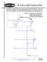
Figure 1. Possible Evaporative Cooling System Layouts (top view)
System Layout Diagrams
Several system layouts are shown in Figure 1, Below.
Water and Electrical Supply Requirements
Water Supply: The water supply must be capable of providing 1 g.p.m. at 30 p.s.i. for
each 100 sq. ft. of pad.
Note: A booster pump must be used if the existing water supply is not capable of
supplying this water pressure to the spray lines. If a booster pump is
required, see the Control Panel Installation section, on page 14 for pump
location.
Water PH level must be between 6 and 9. Water with too high or too low PH level will
cause premature pad deterioration.
Electrical Supply: The Water Solenoid on the Control Panel requires 230 V, 50/60 Hz.,
single phase electrical power.
Key Description
1 Cooling Pads
2 Tunnel Fans

Mister Cool™ Evaporative Cooling Manual
7
Pad Area Requirements
Three (3) ft
2
of cooling pad is required for each 1,000 c.f.m. of Tunnel Fan capacity. If
fan performance data is not available, assume 20,000 c.f.m. for each 48" Fan, 10,000
c.f.m. for each 36” Fan, and 6,000 c.f.m. for each 24" Fan.
For example, a house with (8) 48" tunnel fans would require approximately 480 ft
2
of
Cooling Pad. Calculation: Total c.f.m = 160,000 divided by 1,000 = 160 x 3 (ft
2
) = 480 ft
2
.
Select Pad Height
Spray Pads are available in 4' (1.2 m), 5' (1.5 m) 6' (1.8 m) heights. Pad height is
determined by the height of the tunnel opening and the available wall space to hang the
pad.
Calculate Total Pad Length
To calculate the total pad length, divide the pad area by the pad height.
Nozzle Spacing
Nozzle spacing is determined by the available water pressure and the pad height. See
the Chart below for the appropriate (horizontal) spacing between the nozzles. The
nozzle spacing listed in the table will provide 1 gallon/minute of water per 100 ft
2
of
pad.
If the water supply system is not capable of providing 30 p.s.i. to the nozzles, a booster
pump must be used. To calculate the total water pressure with a booster pump, add the
pressure the booster pump will supply to the water system supply pressure.
Pad Height Tunnel Opening
4' (1.2 m) 3' - 4' (.9 m - 1.2 m)
5' (1.5 m) 4' - 5' (1.2 m - 1.5 m)
6' (1.8 m) 5' - 6' (1.5 m - 1.8 m)
Water Pressure
at the Nozzles
(P.S.I.)
Pad Height
4' (1.2 m) 5' (1.5 m) 6' (1.8 m)
30 15" (38 cm) 12" (30 cm) 10" (25 cm)
40 17" (43 cm) 13" (33 cm) 12" (30 cm)
50 -- 15" (38 cm) 13" (33 cm)
60 -- 17" (43 cm) 15" (38 cm)
70 -- 17" (43 cm) 15" (38 cm)
80 -- -- 17" (43 cm)
90 -- -- 17" (43 cm)
100 -- -- 17" (43 cm)

8
Mister Cool™ Evaporative Cooling Manual
Evaporative Cooling System Installation
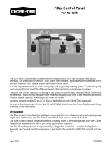
A system overview is provided in Figure 2, below. Figures 3 - 8 provide specific
installation details and dimensions.
Figure 2. Evaporative Cooling System Overview (side view: left, front view: right)
Key Description
1 Truss Extension
2 Chain & S Hooks
3 Hanger
4 Curtains
5 Water Lines w/ Nozzles
6 Evaporative Cooling Pad
7 Gutter
8 Water Supply Lines

Mister Cool™ Evaporative Cooling Manual
9
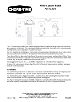
Figure 3. Framing Dimensions (side view)
1
Frame
Opening
Height
2
Tunnel
Opening
3
Pad
Height
4
Min. Wall
Height
Requirement
5
Distance from
curtain to pad
45" (1.14 m) 3' - 4' (.9 - 1.2 m) 48" (1.2 m) 58" (1.47 m) 8" - 10" (20 - 25 cm)
57" (1.44 m) 4' - 5' (1.2 - 1.5 m) 60" (1.5 m) 70" (1.78 m) 8" - 10" (20 - 25 cm)
69" (1.75 m) 5' - 6' (1.5 - 1.8 m) 72" (1.8 m) 82" (2.08 m) 8" - 10" (20 - 25 cm)
A frame should be built to hold the pad 8" - 10" (20 cm to 25 cm) from the side wall.
See Figure 3.
The tunnel curtain should be installed inside this frame between the spray pad and the
screen covering the tunnel opening.
The length of the frame should be equal to the pad length.
The height of the frame opening should be 3" (7.6 cm) shorter than the pad to allow for
1.5" (4 cm) of overlap at the top and bottom.
Note: Be sure to allow adequate space above the frame or inside the top of the
frame for the curtain cables and pulleys.

10
Mister Cool™ Evaporative Cooling Manual
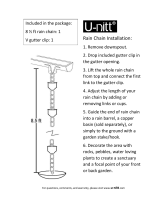
Figure 4. Gutter Installation
Gutter Installation
The Gutter sections are secured together using a Gutter Coupler. Apply caulk to the
both sides and the bottom of the Gutter Couplers. Use a Gutter Coupler and (4) 1/2"
Self-Drilling Screws to secure the Gutter sections together. See Figure 4.
Apply caulk around the End Cap and install on the high end of the Gutter, using (3)
1/2" Self-Drilling Screws. The Gutter may be shortened as required using a hacksaw or
tin snips.
Hang the Gutter using four (4) 1" self drilling screws placed equally apart (supplied per
length of gutter), so that it slopes 1/2" (12 mm) over the total length of the Gutter.
Some water runoff should be expected. Therefore, it may be desirable to install a drain
under the Gutter to route the runoff away from the building.
Key Description
1 1/2" (13mm) Slope over the total length of the gutter
2 (4) 1" Self-Drilling Screw
3 Tunnel Opening
4 Gutter
5 Gutter Coupler
6 (2) Beads of Caulk
7 1/2" Self-Drilling Screw
8 Gutter End Cap
9 1/4" at the high end of the Gutter

Mister Cool™ Evaporative Cooling Manual
11
Key Description
1 Secure pads to framework through wire hangers. Two screws and washers per pad.
2 Pad
3 3/4" (19 mm) minimum gap
4 Wire Hanger
5 Gutter
6 Minimize gap by pushing pads together as they are being installed.
7 Frame end panel
Figure 5. Pad Installation (side view: left, front view: right)
Pad Installation
The pad sections include a Wire Hanger on the top end. Fasten the pads to the
framework using #10 x 1-1/2" screws and 1-1/4” washers through the Wire Hangers.
See Figure 5.
The pads must be:
n installed as vertically straight as possible.
n installed tightly against each other. Try to minimize the gap between the pads. It
is better to have the pads squeezed together than to allow large gaps between
them.
n installed so that the pads do not rest in the Gutter. Allow at least 3/4" (19 mm) of
clearance between the bottom of the pad and the bottom of the Gutter.
n installed to fit tight against the frame at both ends of pads.
Note: The pad may be cut to size using a hand saw. Wire cutters are required to
cut the Wire Hangers.

12
Mister Cool™ Evaporative Cooling Manual
Hanger Installation
The Hangers must be installed so that the spray nozzles will be located as specified in
Figure 6.
Key Description
1 Pad
2 Water Pipes w/Nozzles
3 For 4' Pad: 17" - 19" (43 - 48 cm)
For 5' Pad: 26" - 28" (66 - 71 cm)
For 6' Pad: 33" - 35" (84 - 90 cm)
4 12" (30 cm)
5 Hanger
6 12" - 14" (30 - 36 cm)
7 2" (51 mm)
The Hangers may be installed a variety of ways depending upon your particular
installation. Four are shown in Figure 7. The Hangers should be installed on a
maximum of 5' (1.5 m) centers.
The Hangers may be secured directly to the trusses. The Hangers may be hung from the
trusses using chain and “S” Hooks. Or, Truss Extenders may be required to install the
Hangers.
Figure 6. Recommended Nozzle
locations (side view)
Figure 7. Hanger Installation Options (side view)
Key Description
1 Truss
2 Hanger
3 Truss Extenders
4 Chain and “S” Hooks
5 Nail or screw (not supplied)
6 10-16 x 1-1/2" Screw

Mister Cool™ Evaporative Cooling Manual
13
Pipe Installation
Snap the pipes into the Hangers at the spacings specified in Figure 6 on page 11. The
first and last nozzle on each line should be approximately 8" - 12" (20 - 30 cm) from
the end of the pad.
Note: It may help to turn the pipe while snapping it into the Hanger.
Refer to the chart to determine the appropriate location for the bottom line of nozzles.
Cement the pipe sections together, using PVC Cement and PVC Couplers. Chore-Time
recommends using PVC Pipe Cleaner (not supplied) to prepare the pipe ends for
joining.
The nozzles must be pointing straight toward the pad. See Figure 8.
If the pipes must be cut, use pipe cutters (using a saw may leave debris in the lines,
plugging the nozzles).
Glue a shut-off valve on the drain end of each line. See Figure 8.
Assemble and glue the supply end components to the supply end of the water lines.
Connect the assemblies with the 3/4" pipe supplied after cutting it to length. See Figure 8.
Connect the spray lines to the supply line with the rubber hose and PVC Adapter, as
shown in Figure 8.
Figure 8. Pipe Installation (front view)
Key Description Key Description
1 Hanger 7 3/4" PVC Adapter
2 Shut-Off Valve 8 3/4" Pipe
3 Spray Line w/Nozzles 9 Elbow Valve Assembly
4 PVC Coupler 10 Pad
5 Regulator Assembly 11 8" - 12" (20 - 30 cm)
6 4' Hose w/Fittings

14
Mister Cool™ Evaporative Cooling Manual
Figure 9. Control Panel Installation (front view)
Key Description
1 Inlet Supply Hook-Up
2 Control Panel
3 Outlet Hook-Up
4 Water Solenoid Manual Bypass Valve
Wiring the System
Wire the solenoid valve on the control panel as specified in the appropriate diagram for
your system. See Figures 10 - 13.
Figure 10. System wiring when controlled by a Chore-Time Super-Selector Control.
Control Panel Installation
Mount the Control Panel on the wall See Figure 9.
If the water system supply pressure is less than 20 p.s.i., connect the booster pump
between the Control Panel inlet and the water supply line. Do not connect a booster
pump larger than 1/3 H.P. to the inlet end of the Control Panel.
If the existing line pressure is greater than 20 p.s.i., connect the booster pump to the
outlet end of the Control Panel.
Plumb the lines from the Control Panel/Booster Pump to the spray lines based on the
following specifications.
Use 1" (2.5 mm) pipe if the water pressure at the Control Panel is less than 35 psi and
the distance to the nozzles is greater than 100 feet (30 m).
All other systems use 3/4" (19 mm) pipe.
Connect the spray lines to the supply line with the rubber hose.

Mister Cool™ Evaporative Cooling Manual
15
Figure 11. System wiring when controlled by a single thermostat.
Figure 12. System wiring when controlled by a single thermostat and cycle timer.
Figure 13. System wiring when controlled by two thermostats and cycle timer.

16
Mister Cool™ Evaporative Cooling Manual
Operating Recommendations
n After the installation is complete, open the valves at the end of the spray lines.
Allow the water to run for several minutes to clean any dirt or debris from the lines.
n The Spray Pad Evaporative Cooling system may be controlled in a variety of ways
(i.e. Super-Selector Control, single or multiple thermostats, timers, etc.). To
control water run-off from the pad, some type of timer/temperature controller
should be used.
n Some water runoff from the pads is required to minimize the accumulation of dirt
and build-up on the cooling pads.
n For tunnel ventilated buildings, Chore-Time recommends using the Super-Selector
Control. Refer to Figure 10 for wiring information when using a Super-Selector
Control.
n Use the “I” knob (on the Super-Selector) in conjunction with the Auxiliary Timer
to control the first stage of cooling. The “H” knob controls the second stage of
cooling. The solenoid valve will remain open as long as the “H” output is ON.
n The most basic control for the Spray Pad Evaporative Cooling System is a single
thermostat. The thermostat should be wired to open the solenoid when the
temperature rises above the thermostat set point. See Figure 11.
n Adding an ON/OFF Timer in series with the single thermostat provides a means of
reducing excessive water runoff at low set point temperatures. The time should be
set so that the “ON” time is long enough for the pad to be completely wetted. The
“OFF” time should be short enough that the pad does not dry out. Refer to
Figure 12 for wiring information for this type of system.
n Further, a second thermostat may be wired in parallel with the first thermostat and
timer to provide second stage of cooling. This thermostat can be used to hold the
solenoid open allowing for maximum amount of water to be sprayed onto the pad.
This will provide the maximum amount of cooling. Refer to Figure 13 for wiring
information for this type of system.
n The Manual By-Pass Valve on the Control Panel may be used to supply water to
the nozzles when the solenoid is “OFF”.
System Maintenance
n Clean the cooling pads by spraying with a garden hose and scrubbing with a stiff
brush.
n Clean or change the water filter cartridge when the pressure gauges indicate a
5 p.s.i. or greater pressure drop across the filter.
n Each week, open the valves at the end of the spray lines. This will help flush build-
up off the nozzle screens. Allow the water to run at full pressure for several
minutes.
n At the end of the cooling season, drain the lines to prevent sediment build-up and
freezing or breaking of the spray lines.
Trouble Shooting Guidelines
If the nozzles do not produce a full spray pattern:
1. Make sure the water supply to the nozzles is at least 30 p.s.i.
2. Flush the lines to remove sediment or build-up on the nozzle screens.
3. Remove the nozzles and clean the nozzle screens.

Mister Cool™ Evaporative Cooling Manual
17
Item Description Part No.
1 Truss Extender 36655
2 Chain 2128-1
3 “S” Hook 4270
4 Hanger (4') 36631
Hanger (5') 36830
5 Nozzle 36134
6 3/4" SxS Valve 34728
7 Cooling Pad 2"x24"x48" 36264-4
Cooling Pad 2"x24"x60" 36264-5
Cooling Pad 2"x24"x72" 36264-6
8 Gutter End Cap 36658
9 Schedule 120 Pipe (3/4" x 10')
w/ 7 Nozzles 36133-7
w/ 8 Nozzles 36133-8
w/ 9 Nozzles 36133-9
w/10 Nozzles 36133-10
w/12 Nozzles 36133-12
10 3/4" PVC Coupler 7775
11 2" Fogger Pad Gutter 36656
12 Fogger Gutter Coupler 36657
13 Tee-Valve Assembly 36934
14 3/4"Hose w/ Fittings (4' Long) 36654
15 3/4" PVC Adapter 14605
16 3/4" Pipe 7514-10
17 Elbow Valve Assembly 36696
Evaporative Cooling Miscellaneous Parts

18
Mister Cool™ Evaporative Cooling Manual
Spray Pad Control Panel Parts
Part No. 36661
Item Description Part No.
1 3/4" PVC Male Adapter 9229
2 20 Micron Filter Cartridge 7723
3 1" Solenoid Valve 36660
4 Pressure Gauge (100 p.s.i.) 7191
5 Filter Mounting Bracket 35302
6 Water Filter 353097
7 3/4" Union 8137
8 Plastic Standoff Block 35300
9 3/4" Plastic Conduit Clamp 35301
10 Mounting Board 36726
11 3/4" Valve 36720

19
Mister Cool™ Evaporative Cooling Manual
This Page
Currently
Not in Use

Contact your nearby Chore-Time distributor or representative for additional parts and information.
CTB, Inc.
P.O. Box 2000
Milford, Indiana 46542-2000 U.S.A.
Phone: 219-658-4101 • E-Mail: [email protected]
Printed in the U.S.A.
Revisions to this Manual
Page No. Description of Change
17 Part No. changes on cooling pads.
Made to work.
Built to last.
TM
/