Page is loading ...

PDS™ Control 4 and 8 Station
Pneumatic Drinking System
Installation and Operators Manual
MW1402FJanuary 2015

PDS™ Control 4 and 8 Station Limited Warranty
MW1402F
2
Chore-Time Group, a division of CTB, Inc. (“Chore-Time”) warrants new CHORE-TIME Cage and Cage Components
manufactured by Chore-Time to be free from defects in material or workmanship under normal usage and conditions, for
One (1) year from the date of installation by the original purchaser (“Warranty”). If such a defect is determined by Chore-
Time to exist within the applicable period, Chore-Time will, at its option, (a) repair the Product or Component Part free of
charge, F.O.B. the factory of manufacture or (b) replace the Product or Component Part free of charge, F.O.B. the factory of
manufacture. This Warranty is not transferable, and applies only to the original purchaser of the Product.
CONDITIONS AND LIMITATIONS
THIS WARRANTY CONSTITUTES CHORE-TIME’S ENTIRE AND SOLE WARRANTY AND CHORE-TIME
EXPRESSLY DISCLAIMS ANY AND ALL OTHER WARRANTIES, INCLUDING, BUT NOT LIMITED TO,
EXPRESS AND IMPLIED WARRANTIES, INCLUDING, WIHTOUT LIMITATION, WARRANTIES AS TO
MERCHANTABILITY OR FITNESS FOR PARTICULAR PURPOSES. CHORE-TIME shall not be liable for any direct,
indirect, incidental, consequential or special damages which any purchaser may suffer or claim to suffer as a result of any
defect in the Product. Consequential or Special Damages as used herein include, but are not limited to, lost or damaged
products or goods, costs of transportation, lost sales, lost orders, lost income, increased overhead, labor and incidental costs,
and operational inefficiencies. Some jurisdictions prohibit limitations on implied warranties and/or the exclusion or
limitation of such damages, so these limitations and exclusions may not apply to you. This warranty gives the original
purchaser specific legal rights. You may also have other rights based upon your specific jurisdiction.
Compliance with federal, state and local rules which apply to the location, installation and use of the Product are the
responsibility of the original purchaser, and CHORE-TIME shall not be liable for any damages which may result from non-
compliance with such rules.
The following circumstances shall render this Warranty void:
· Modifications made to the Product not specifically delineated in the Product manual.
· Product not installed and/or operated in accordance with the instructions published by the CHORE-TIME.
· All components of the Product are not original equipment supplied by CHORE-TIME.
· Product was not purchased from and/or installed by a CHORE-TIME authorized distributor or certified
representative.
· Product experienced malfunction or failure resulting from misuse, abuse, mismanagement, negligence, alteration,
accident, or lack of proper maintenance, or from lightning strikes, electrical power surges or interruption of
electricity.
· Product experienced corrosion, material deterioration and/or equipment malfunction caused by or consistent with
the application of chemicals, minerals, sediments or other foreign elements.
· Product was used for any purpose other than for the care of poultry and livestock.
The Warranty and Extended Warranty may only be modified in writing by an officer of CHORE-TIME. CHORE-TIME
shall have no obligation or responsibility for any representations or warranties made by or on behalf of any distributor,
dealer, agent or certified representative.
Effective: April, 2014
Chore-Time Group
A division of CTB, Inc.
PO Box 2000
Milford, Indiana 46542-2000 USA
Phone (574) 658-4101 Fax (877) 730-8825
E-mail: www.choretimepoultry.com
Internet: poultr[email protected]
Limited Warranty

PDS™ Control 4 and 8 Station
3
MW1402F
Limited Warranty. . . . . . . . . . . . . . . . . . . . . . . . . . . . . . . . . . . . . . . . . . . . . . . . . . . . . . . . . . . . . . . .2
About This Manual . . . . . . . . . . . . . . . . . . . . . . . . . . . . . . . . . . . . . . . . . . . . . . . . . . . . . . . . . . . . . . .4
Safety Information . . . . . . . . . . . . . . . . . . . . . . . . . . . . . . . . . . . . . . . . . . . . . . . . . . . . . . . . . . . . . . .4
Safety Instructions. . . . . . . . . . . . . . . . . . . . . . . . . . . . . . . . . . . . . . . . . . . . . . . . . . . . . . . . . . . . . . . .5
Follow Safety Instructions. . . . . . . . . . . . . . . . . . . . . . . . . . . . . . . . . . . . . . . . . . . . . . . . . . . . . . . . . . . . . . .5
Decal Descriptions. . . . . . . . . . . . . . . . . . . . . . . . . . . . . . . . . . . . . . . . . . . . . . . . . . . . . . . . . . . . . . . . . . . . .5
DANGER: Electrical Hazard. . . . . . . . . . . . . . . . . . . . . . . . . . . . . . . . . . . . . . . . . . . . . . . . . . . . . . . . .5
General. . . . . . . . . . . . . . . . . . . . . . . . . . . . . . . . . . . . . . . . . . . . . . . . . . . . . . . . . . . . . . . . . . . . . . . . .5
Support Information. . . . . . . . . . . . . . . . . . . . . . . . . . . . . . . . . . . . . . . . . . . . . . . . . . . . . . . . . . . . . . . . . . . .5
Installation Information . . . . . . . . . . . . . . . . . . . . . . . . . . . . . . . . . . . . . . . . . . . . . . . . . . . . . . . . . . . . . . . . .5
The System Layout . . . . . . . . . . . . . . . . . . . . . . . . . . . . . . . . . . . . . . . . . . . . . . . . . . . . . . . . . . . . . . .6
Broiler System Layout. . . . . . . . . . . . . . . . . . . . . . . . . . . . . . . . . . . . . . . . . . . . . . . . . . . . . . . . . . . . . . . . . .6
Multiple House Layout . . . . . . . . . . . . . . . . . . . . . . . . . . . . . . . . . . . . . . . . . . . . . . . . . . . . . . . . . . . . . . . . .6
Installation. . . . . . . . . . . . . . . . . . . . . . . . . . . . . . . . . . . . . . . . . . . . . . . . . . . . . . . . . . . . . . . . . . . . . .7
Wiring . . . . . . . . . . . . . . . . . . . . . . . . . . . . . . . . . . . . . . . . . . . . . . . . . . . . . . . . . . . . . . . . . . . . . . . . . . . . . .7
CHORE-TRONICS® . . . . . . . . . . . . . . . . . . . . . . . . . . . . . . . . . . . . . . . . . . . . . . . . . . . . . . . . . . . . . . .7
Tubing . . . . . . . . . . . . . . . . . . . . . . . . . . . . . . . . . . . . . . . . . . . . . . . . . . . . . . . . . . . . . . . . . . . . . . . . . . . . . .9
Adjust Air supplied to the PDS Control. . . . . . . . . . . . . . . . . . . . . . . . . . . . . . . . . . . . . . . . . . . . . . . . . . . . .9
Air Pressure Gauge. . . . . . . . . . . . . . . . . . . . . . . . . . . . . . . . . . . . . . . . . . . . . . . . . . . . . . . . . . . . . . . . .9
Regulator Minimum Water Column Provision . . . . . . . . . . . . . . . . . . . . . . . . . . . . . . . . . . . . . . . . . . . . . . .9
Start Up . . . . . . . . . . . . . . . . . . . . . . . . . . . . . . . . . . . . . . . . . . . . . . . . . . . . . . . . . . . . . . . . . . . . . . . 10
Step 1: Charging the Lines. . . . . . . . . . . . . . . . . . . . . . . . . . . . . . . . . . . . . . . . . . . . . . . . . . . . . . . . . . . . . . 10
Caution: DO NOT FLUSH DRINKER LINES WITH PDS™ CONTROL unless drinker lines are pressurized with wa-
ter! Damage may occur if this caution is not followed. . . . . . . . . . . . . . . . . . . . . . . . . . . . . . . . . . . . . . . . . . . . 10
Step 2: Connecting the compressed air supply . . . . . . . . . . . . . . . . . . . . . . . . . . . . . . . . . . . . . . . . . . . . . . 10
Step 3: Water Column Gauge Calibration . . . . . . . . . . . . . . . . . . . . . . . . . . . . . . . . . . . . . . . . . . . . . . . . . . 11
Step 4: Air Leak Test. . . . . . . . . . . . . . . . . . . . . . . . . . . . . . . . . . . . . . . . . . . . . . . . . . . . . . . . . . . . . . . . . . 11
Operation. . . . . . . . . . . . . . . . . . . . . . . . . . . . . . . . . . . . . . . . . . . . . . . . . . . . . . . . . . . . . . . . . . . . . . 11
Flushing The System. . . . . . . . . . . . . . . . . . . . . . . . . . . . . . . . . . . . . . . . . . . . . . . . . . . . . . . . . . . . . 12
Flushing Recommendations . . . . . . . . . . . . . . . . . . . . . . . . . . . . . . . . . . . . . . . . . . . . . . . . . . . . . . . 14
When to flush the system. . . . . . . . . . . . . . . . . . . . . . . . . . . . . . . . . . . . . . . . . . . . . . . . . . . . . . . . . . . . . . . 14
Flushing for Sediment, Air Locks, and Cleaning . . . . . . . . . . . . . . . . . . . . . . . . . . . . . . . . . . . . . . . . . 14
Flushing After Introduction of Water Treatment or Bird Health Products. . . . . . . . . . . . . . . . . . . . . . 14
Flush to Stimulate Birds to Drink. . . . . . . . . . . . . . . . . . . . . . . . . . . . . . . . . . . . . . . . . . . . . . . . . . . . . 14
Maintenance. . . . . . . . . . . . . . . . . . . . . . . . . . . . . . . . . . . . . . . . . . . . . . . . . . . . . . . . . . . . . . . . . . . . 14
Troubleshooting. . . . . . . . . . . . . . . . . . . . . . . . . . . . . . . . . . . . . . . . . . . . . . . . . . . . . . . . . . . . . . . . . 15
Parts Listing. . . . . . . . . . . . . . . . . . . . . . . . . . . . . . . . . . . . . . . . . . . . . . . . . . . . . . . . . . . . . . . . . . . . 16
4 Station PDS™ Control: 52430-4 . . . . . . . . . . . . . . . . . . . . . . . . . . . . . . . . . . . . . . . . . . . . . . . . . . . . . . . 16
8 Station PDS™ Control: 52430-8 . . . . . . . . . . . . . . . . . . . . . . . . . . . . . . . . . . . . . . . . . . . . . . . . . . . . . . . 16

PDS™ Control 4 and 8 Station About This Manual
MW1402F
4
The intent of this manual is to help you in two ways. One is to follow step-by-step in the order of assembly of your
product. The other way is for easy reference if you have questions in a particular area.
Important: Read ALL instructions carefully before starting construction.
Important: Pay particular attention to all SAFETY information.
• Metric measurements are shown in millimeters and in brackets, unless otherwise specified. “ " ” equals inches
and “ ' ” equals feet in English measurements.
Examples:
1" [25.4]
4' [1.219]
• Optional equipment contains necessary instructions for assembly or operation.
• Very small numbers near an illustration (i.e.,
1257-48) are identification of the graphic, not a part number.
Note: The original, authoritative version of this manual is the English version produced by CTB, Inc. or any of
its subsidiaries or divisions, (hereafter collectively referred to as "CTB"). Subsequent changes to any manual
made by any third party have not been reviewed nor authenticated by CTB. Such changes may include, but are
not limited to, translation into languages other than English, and additions to or deletions from the original
content. CTB disclaims responsibility for any and all damages, injuries, warranty claims and/or any other
claims associated with such changes, inasmuch as such changes result in content that is different from the
authoritative CTB-published English version of the manual. For current product installation and operation
information, please contact the customer service and/or technical service departments of the appropriate CTB
subsidiary or division. Should you observe any questionable content in any manual, please notify CTB
immediately in writing to: CTB Legal Department, P.O. Box 2000, Milford, IN 46542-2000 USA.
Caution, Warning and Danger Decals have been placed on the equipment to warn of potentially dangerous
situations. Care should be taken to keep this information intact and easy to read at all times. Replace missing or
damaged safety decals immediately.
Using the equipment for purposes other than specified in this manual may cause personal injury and/or damage to
the equipment.
Safety–Alert Symbol
This is a safety–alert symbol. When you see this symbol on your equipment, be alert to the
potential for personal injury. This equipment is designed to be installed and operated as safely
as possible...however, hazards do exist.
Understanding Signal Words
Signal words are used in conjunction with the safety–alert symbol to identify the severity of the warning.
DANGER indicates an imminently hazardous situation which, if not avoided, WILL result in death or
serious injury.
WARNING indicates a potentially hazardous situation which, if not avoided, COULD result in death or
serious injury.
CAUTION indicates a hazardous situation which, if not avoided, MAY result in minor or moderate
injury.
About This Manual
Safety Information

Safety Instructions PDS™ Control 4 and 8 Station
5
MW1402F
Follow Safety Instructions
Carefully read all safety messages in this manual and on your equipment safety signs. Follow recommended
precautions and safe operating practices.
Keep safety signs in good condition. Replace missing or damaged safety signs.
Decal Descriptions
DANGER: Electrical Hazard
Disconnect electrical power before inspecting or servicing equipment
unless maintenance instructions specifically state otherwise.
Ground all electrical equipment for safety.
All electrical wiring must be done by a qualified electrician in accordance
with local and national electric codes.
Ground all non-current carrying metal parts to guard against electrical
shock.
With the exception of motor overload protection, electrical disconnects and
over current protection are not supplied with the equipment.
Support Information
The Chore-Time 4 and 8 Station Pneumatic Drinking System (PDS™) Controls are designed to control water line
regulators in a Chore-Time Nipple Watering System. Using this equipment for any other purpose or in a way not
within the operating recommendations specified in this manual will void the warranty and may cause personal
injury.
This manual is designed to provide comprehensive planning and installation information. The Table of Contents
provides a convenient overview of the information in this manual.
Installation Information
Please read the installation instructions in this manual prior to beginning the installation. This manual provides
the necessary information on the installation, operation and maintenance of the Chore-Time equipment you have
purchased.
The 4 and 8 Station PDS™ Control is available in either a 4 or 8 station control. Each station is capable of
controlling up to two (2) individual Chore-Time water regulators. For example a 4 station control can regulate and
flush up to 8 individual water regulators.
Compressed air must be available and regulated between 6 and 12 psi [41.37 and 82.74 kPa]. Each PDS™ control
consumes a low volume of air when in operation. Therefore, one centrally located air compressor with a holding
tank can easily supply enough air for multiple PDS™ controls. See “Adjust Air supplied to the PDS Control” on
page 9 of this manual for recommended air compressor specifications.
Safety Instructions
General

PDS™ Control 4 and 8 Station The System Layout
MW1402F
6
Below are examples of the Chore-Time Nipple Watering system layouts. These are to be used to show different
methods for installing the PDS™ system. Refer to Parts List Section, page 16 for item part numbers.
Broiler System Layout
Figure 1. Broiler Layout
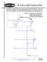
Multiple House Layout
Figure 2. (4 House Layout)
Air can be run from a central location to supply multiple houses. Air lines can consist of Chore-Time tubing (Part
number 45895-500), which will supply a sufficient air supply, or PVC plumbing.
The System Layout

Installation PDS™ Control 4 and 8 Station
7
MW1402F
Locate the control in a convenient location where it can easily be seen and adjusted.
Fasten the control to the wall through the four holes in the corners (mounting hardware not supplied)
Figure 3. Mounting orientation
Wiring
Caution: Be sure power to the Control is still disconnected!
All wiring must be done by a qualified electrician in accordance with local and national codes.
Note: No backup battery needed! All timer settings are stored indefinitely in memory.
CHORE-TRONICS
®
When using CHORE-TRONICS
®
to monitor water consumption, flush water can be automatically subtracted
from the water usage through the meter. To do this connect one wire to common and one wire to MV both
in the Rain Bird Timer. Run these two wires to a 24VAC Coil Relay (not supplied), from the relay run the
two wires to the Chore-Tronics control, see figure 4.
Installation
Mounting Hole Locations
Top of Control
Shown with Control
Lid Open


Installation PDS™ Control 4 and 8 Station
9
MW1402F
Tubing
Route the regulator tubing so any
condensation in the air lines will not run into
the control. Allow slack in the regulator tube
leads so that they can be pinched for
maintenance and diagnostic purposes, see
figure 6.
Connect the regulator tubing to the control
tube leads using tube couplings. Warming
the end of the tubing will aid in installation.
Caution: Over-Heating of tube
end can cause distortion and leaking.
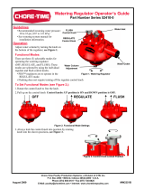
Adjust Air supplied to the PDS Control
Caution: DO NOT FLUSH DRINKER LINES WITH PDS™ CONTROL unless drinker
lines are pressurized with water! Damage may occur if this caution is not followed.
BEFORE connecting the compressed air supply to
the control, turn the red adjustment knob on the PDS
control clockwise (decrease) until the knob stops
turning, see figure 7.
BEFORE connecting the compressed air supply to
the control, the compressed air supplied to the
PDS™ control, must be regulated between 6 and
12 psi [41.37 and 82.74 kPa]. Failure to do this will
result in damage to the gauges and possibly other
components. After the air supplied from the
compressor is confirmed to be between 6 and 12 psi
[41.37 and 82.74 kPa], connect the air supply to the
incoming pressure line on the PDS control, see figure
7.
Air Pressure Gauge
The PDS Control has an Air Pressure Gauge (see
figure 8.) to monitor the incoming air pressure. Under
normal operating conditions, this gauge should show
between 6 and 12 psi [41.37 and 82.74 kPa] of air
pressure.
Regulator Minimum Water Column Provision
In the event of air pressure loss to the PDS Control an internal spring in the Regulator will maintain a minimum
water column height until the air supply can be restored. This minimum water pressure will be in the 4" to 6"
[10.2cm to 15.2cm] range and will vary with the incoming water supply pressure. The PDS Control cannot adjust
the water column height below this minimum.
Figure 6. Regulator Tube Leads
Regulator Tubing
PDS Control
Figure 7. Adjusting the water column
Adjustment Knob
Figure 8. Air Pressure Gauge

PDS™ Control 4 and 8 Station Start Up
MW1402F
10
Step 1: Charging the Lines
Caution: DO NOT FLUSH DRINKER LINES WITH PDS™ CONTROL unless drinker
lines are pressurized with water! Damage may occur if this caution is not followed.
Lines may however, be flushed at any time using the manual flush feature built into the Regulator.
Once all the tubing has been ran from the Control and connected to the Regulators and before compressed air is
connected to the PDS Control, the drinker lines should be charged with water. This can be done by turning the
selector knob on each Regulator to the "ON" position. It is recommended to charge two lines at a time.
Step 2: Connecting the compressed air supply
Air compressor (not supplied) guidelines to operate the system.
• All air compressors must have a minimum rating to run 4 times per hour for 5 minutes each run.
• One (1) PDS™ Control - 2 gallon minimum recommended air supply tank.
• Two (2) - four (4) PDS™ Controls - 5 gallon minimum recommended air supply tank.
• Five (5) - six (6) PDS™ Controls - 10 gallon minimum recommended air supply tank.
• Air regulator with 1/4" fitting.
• Approved air regulators:
• Grainger Industrial Supply Part number 4ZMO8
• Grainger Industrial Supply Part number 4ZMO6
• NAPA Part number 90-725
Note: The PDS Control operates between 6 & 12 psi [41.37 kPa & 82.74 kPa]. Most air Regulators
supplied with air compressors will not effectively regulate air pressure at this low pressure. Chore-
Time recommends using one of the approved air regulators listed above.
Caution: DO NOT FLUSH DRINKER LINES WITH PDS™ CONTROL unless drinker
lines are pressurized with water! Damage may occur if this caution is not followed.
Lines may be flushed at any time using the manual flush mode feature built into the Regulator
Each regulator tubing lead may be used to supply air to two nipple line regulator inlets. This will assure enough
flush water volume per line to move air and sediment down the nipple lines and out.
Run each air supply tube across the ceiling to a 1/4" tee to split the
line and then follow the Regulator water supply line down to the
Regulator and attach it using the air supply connection. see figure
9.
Start Up
Figure 9. Air Supply to Regulator
Air Supply
Connection

Operation PDS™ Control 4 and 8 Station
11
MW1402F
Step 3: Water Column Gauge Calibration
Turn the red adjustment knob counter-clockwise (increase) until the water column gauge reads 14 inches [35.56
cm], see figure 10.
After installation of the PDS regulators make sure all the water
lines are flushed and charged. Then measure the water column
at one of the water regulators and confirm 14 inches of water
column. If anything other than 14 inches is measured at the stand
tube, the water column gage will need to be re-calibrated to that
measurement.
To re-calibrate the water column gauge remove the plastic cover
with a small screwdriver. Then turn the calibration screw (see
figure 10.) until the gauge reads the same water column height
as the measurement. Replace the plastic cover on the gauge.
Step 4: Air Leak Test
Check each control and house for air leaks with the water column gauge at 8 inches [20.32 cm]. To check for air
leaks in the control or the house pinch the incoming air supply tube to shut off the incoming air pressure. Watch
the air pressure gauge on the control, the gauge should not drop any more than 2 psi [13.79 kPa] in 1 minute. If
the air pressure does drop faster than 2 psi [13.79 kPa] in 1 minute, refer to the trouble shooting section on
page 15. Repeat this procedure for every PDS control.
The PDS control will adjust the regulator water column
height at all the regulators. To adjust the water column
height, turn the red adjustment knob counter-clockwise
to increase and clock-wise to decrease (see figure 11.)
until the water column gauge reads the desired water
column height.
Note: Individual PDS regulators provide a minimum
water column height in case air pressure is
lost. The regulators CAN NOT be adjusted
below this height regardless of the water
column gauge reading.
Operation
Figure 10. Water Column Gauge
Calibration
Screw
Figure 11. Adjusting the water column

PDS™ Control 4 and 8 Station Flushing The System
MW1402F
12
Caution: DO NOT FLUSH DRINKER LINES WITH PDS™ CONTROL unless drinker
lines are fully charged with water! Damage may occur if this caution is not
followed.
Refer to the Rain Bird Timer manual for specific programing details.
Single stations or multiple stations may be
manually flushed at any time. Refer to
Operating the Sprinkler Timer section in
the Rain Bird manual.
When birds go out it is a good idea to turn the
Rain Bird
®
Timer to the off position and turn
the adjustment knob on the PDS control to the
minimum setting.
The actual amount of time it takes to
completely change the water in a 3/4" drinker
line is dependent on the flow rate through the
line. This flow rate can easily be estimated by
putting the regulator into flush and timing how
long it takes to fill a container of known
volume at the drain end of the line. Once this
time is determined use the formula below to calculate the flow rate in gallons or liters per minute and then refer
to the charts on page 13 to determine the estimated flush time in minutes for your specific line length.
For example, if it takes 185 seconds to fill a 5 gallon container the resulting flow rate would be 1.6 GMP.
Flushing The System
Volume of Container (Gallons or Liters) = Flow Rate in Gallons or Liters per Minute
Seconds to Fill Container Divided by 60
5 Gallons = 5 = 1.6 Gallons per Minute.
185/60 3.08
Figure 12. Operating the control

Flushing The System PDS™ Control 4 and 8 Station
13
MW1402F
Minutes to Flush and Total Line Capacity
for Chore-Time Nipple Systems
Estimated flush times above are to completely exchange the water in the pipe. The water line length must include
the length of the supply line from the water source to completely exchange the water. The flush time to stimulate
bird drinking may be less, depending on the frequency of flushes.
Water Line Length in Feet
100’ 200’ 300’ 400’ 500’ 600’ 700’ 800’
Gallons per Minute
Flow Rate
1 3.4 6.8 10.2 13.6 17.0 20.4 23.8 27.2
2 1.7 3.4 5.1 6.8 8.5 10.2 11.9 13.6
3 1.1 2.3 3.4 4.5 5.7 6.8 7.9 9.1
4 0.9 1.7 2.6 3.4 4.3 5.1 6.0 6.8
5 0.7 1.4 2.0 2.7 3.4 4.1 4.8 5.4
6 0.6 1.1 1.7 2.3 2.8 3.4 4.0 4.5
7 0.5 1.0 1.5 1.9 2.4 2.9 3.4 3.9
8 0.4 0.9 1.3 1.7 2.1 2.6 3.0 3.4
Estimated Flush Time in Minutes
Total Line
Capacity
3.4
Gallons
Total Line
Capacity
6.8
Gallons
Total Line
Capacity
10.2
Gallons
Total Line
Capacity
13.6
Gallons
Total Line
Capacity
17.0
Gallons
Total Line
Capacity
20.4
Gallons
Total Line
Capacity
23.8
Gallons
Total Line
Capacity
27.2
Gallons
Gallons of water in one foot of 3/4" Chore-Time water pipe=.034
Water Line Length in Meters
30m 60m 90m 120m 150m 180m 210m 240m
Liters Per Minute
Flow Rate
4 3.2 6.3 9.5 12.7 15.8 19.0 22.2 25.3
6 2.1 4.2 6.3 8.4 10.6 12.7 14.8 16.9
8 1.6 3.2 4.7 6.3 7.9 9.5 11.1 12.7
10 1.3 2.5 3.8 5.1 6.3 7.6 8.9 10.1
12 1.1 2.1 3.2 4.2 5.3 6.3 7.4 8.4
14 0.9 1.8 2.7 3.6 4.5 5.4 6.3 7.2
16 0.8 1.6 2.4 3.2 4.0 4.7 5.5 6.3
18 0.7 1.4 2.1 2.8 3.5 4.2 4.9 5.6
20 0.6 1.3 1.9 2.5 3.2 3.8 4.4 5.1
22 0.6 1.2 1.7 2.3 2.9 3.5 4.0 4.6
24 0.5 1.1 1.6 2.1 2.6 3.2 3.7 4.2
26 0.5 1.0 1.5 1.9 2.4 2.9 3.4 3.9
28 0.5 0.9 1.4 1.8 2.3 2.7 3.2 3.6
30 0.4 0.8 1.3 1.7 2.1 2.5 3.0 3.4
Estimated Flush Time in Minutes
Total
Line
Capacity
12.7
Liters
Total
Line
Capacity
25.3
Liters
Total
Line
Capacity
38.0
Liters
Total
Line
Capacity
50.6
Liters
Total
Line
Capacity
63.3
Liters
Total
Line
Capacity
76.0
Liters
Total
Line
Capacity
88.6
Liters
Total
Line
Capacity
101.3
Liters
Liters of water in one meter of 3/4" (1.90 cm) Chore-Time water pipe=.422

PDS™ Control 4 and 8 Station Flushing Recommendations
MW1402F
14
Multiple House Application:
Well capacity typically limits the number of water lines that can be flushed at one time. Flushing should be
staggered so 2 lines per well supply are flushed at the same time.
When to flush the system
Single stations or all stations may be manually flushed at any time. Refer to Operating the Sprinkler Timer
section in the Rain Bird Timer manual.
Flushing for Sediment, Air Locks, and Cleaning
Start by flushing several times per flock. Watch the water coming out of the ends of the water lines. If the water
is clean with little or no air you can flush less often. If the water is discolored and has sediment or large
amounts of air you may want to flush more often until these problems disappear. The sediments could react
with medications, vaccines, and electrolytes. They will also hamper the effects of disinfectants and cleaners.
Flushing After Introduction of Water Treatment or Bird Health Products
After running any type of medication, disinfectant, electrolyte, vitamin, or vaccine the lines must be thoroughly
flushed (see the chart on page 13 for estimated flush times). Some products or treatments may require
longer flushing time to be completely removed from the water lines.
Flush to Stimulate Birds to Drink
1. In periods of hot weather flushing will provide cool, fresh water.
2. As birds mature, additional flushing can stimulate the birds to drink more water.
Keep the control box lid closed. The control is not capable of operating in a dusty environment. The loading
regulator vents into the control box. When the control box is sealed the positive internal air pressure keeps dust out
Clean inside and outside of the water line stand tubes at least once a week.
Flushing Recommendations
Maintenance

Troubleshooting PDS™ Control 4 and 8 Station
15
MW1402F
.
Troubleshooting
Problem Correction
No water in Regulator Stand Tube. 1. Water Off.
2. Defective or plugged Regulator.
3. Regulator plumbed backwards.
4. Stand Tube Cap plugged (not venting).
Water Column does not change on a Regulator. 1. Stand Tube Cap plugged (not venting).
2. Air line to Regulator pinched.
Water Column to top of Stand Tube. 1. Regulator seat worn or foreign object in seat area.
2. Stand Tube Cap plugged (not venting).
3. Air Loading Unit putting out too high pressure (defective solenoid).
Compressor suddenly runs more often than
normal.
1. Shut off or pinch off all lines going to the individual controls to find
which house is the problem.
2. Open one line at a time until you find one that causes the compressor
tank to lose air more quickly.
3. See correction for house leak below.
House seems to leak or lose compressed air too
quickly.
1. Shut off the incoming air line to the control and watch the small
INCOMING PRESSURE GAUGE. If the control holds pressure, the
leak is between the air source and that house.
2. With the incoming air off and the gauge indicates that there is a 2
PSI drop or more within 1 minute, the problem is in the control, lines,
or regulators.
3. Shut off or pinch off all lines going out to the regulators and the
incoming line. If the control loses pressure, the problem is inside the
control. See control unit leak below.
4. If the unit holds pressure, release one line at a time to isolate the
cause of the leak.
5. Test line connections and regulator for leaks.
Control unit leaks compressed air. 1. Check the vent hole in the red cover of the Air Loading Unit, see
figure 13. Put soapy water over the hole. A small amount of air
coming out is normal (bubble should grow slowly over several
seconds).
2. Put soapy water on all internal hose connections to find leak.
Vent Hole
Adjustment
Knob
Figure 13. Vent Hole

PDS™ Control 4 and 8 Station Parts Listing
MW1402F
16
4 Station PDS™ Control: 52430-4
8 Station PDS™ Control: 52430-8
*Item sold in Feet.
Parts Listing
52430-4 52430-8 52430-4 52430-8
Item Description Part No Part No Item Description Part No Part No
1 120V Timer Control 52412-1 52412-2 13 Control Box Latch Pivot 30863 30863
2 Hinge 49482 49482 14 Control Box Latch 30862 30862
3 Water Column Gauge 44029 44029 *15 1/4" O.D. Tubing 48574 48574
4 Air Pressure Gauge 48585 48585 16 Control Box Lid 42683 42683
5 Control Plate 52411 52411 17 1/4" Plug 48588 48588
6 Control Decal 2529-939 2529-939 18 Station Number Decal 2526-430 2526-430
7 1/8" Female Pipe Adapter 48586 48586 *19 1/8" Diameter Seal 34767 34767
8 1/2" Machine Washer 2499 2499 20 1/4" Tube Coupling Tee 45894 45894
*9 Gasket 6968-1 6968-1 21 1/4" Tube Coupling 45893 45893
*10 Max Pressure Decal 2526-437 2526-437 22 1/4" O.D. Tubing (500 Ft Roll) 45895-500 45895-500
11 #6-20 x 5/8" Pan Hd Screw 48577 48577
12 Airloader W/Adjustment Knob 48837 48584


MADE TO WORK.
BUILT TO LAST.
®
Revisions to this Manual
Page No. Description of Change
Various Updated warranty, Updated Regulator graphics, Added "Steps", Some other updates
Contact your nearby Chore-Time distributor or representative for additional parts and information.
CTB Inc.
P.O. Box 2000 • Milford, Indiana 46542-2000 • U.S.A.
Phone (574) 658-4101 • Fax (877) 730-8825
E-mail: poultry@choretime.com • Internet: www.choretimepoultry.com
/