Page is loading ...

Lock/Unlock
mode
(Locked position)
0
Passage
mode
Lock
side
Lock
side
Cylinder Function Setting Positions
Lock/Unlock
mode
(Unlocked position)
Retracts latch
by key or turn
Lock/Unlock
mode
(Locked position)
0
Passage
mode
Lock/Unlock
mode
(Unlocked position)
Retracts latch
by key or turn
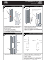
SETTING OF HUB FUNCTION
SETTING OF CYLINDER FUNCTION
1
2
3
TURN KNOB ADAPTORS (If required)
3P80 SERIES MORTICE LOCK
MOUNTING INSTRUCTIONS
CONTENTS
TOOLS REQUIRED
Please ensure that all necessary safety precautions are
undertaken when installing this lockset.
Part No.
Function
3P82TSS-A11E
3P82TSS-E11E
3P82SS-E23E
3P82TSS-E21E
3P82SS-E11E
3P82VSS-E11E
3P82SS-C11D
3P82SS-C21E
3P82SS-C11E
3P72-STA01
3P72-STA01
N/A
3P72-STA01
N/A
3P72-VTA01
N/A
N/A
N/A
A
E
E
E
E
E
C
C
C
SETTING OF LOCK FUNCTION
Fully loosen screw to free hub
selection disc. (Screw will be
retained)
Rotate disc to desired position.
Retighten screw. (Note: Do
not use power driver for this
application.)
Establish functional operation
for the required side of the
door.
1.
Escape (Left side) - Left side handle set to Escape
Escape (Right side) - Right side handle set to Escape
C
A
A
E
E
Combination – both handles lockable
ANTI-LOCKOUT - ‘A’
C
OMBINATION
E
SCAPE SIDE
ANTI-LOCKOUT
E
SCAPE SIDE
‘C’
C
OMBINATION -
ANTI-LOCKOUT
C
OMBINATION
E
SCAPE SIDE -
‘E’
Function setting
tool (supplied)
Indicator Hole
Establish the cylinder function
required on each side of the lock.
Use the Function setting tool
to set the desired position on
each side of the lock.
Feel for 2 ‘clicks’ and ensure the
indicator hole and marks are
aligned.
Cylinder retaining pin
If resetting is required, insert
cylinder retaining pin into
‘RESET’ hole and set to required
position.
Remove cylinder retaining pin.
RESETTING OF CYLINDER
FUNCTION
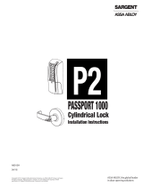
INSTALLATION OF STANDARD
TURN ADAPTOR
Install turn adaptor to inside of
lockset, ensuring cam is engaged.
Insert retainer pin to secure
adaptor in lock.
Ensure lock is in Position 1 and
both sides are in the UNLOCKED
mode.
Install Emergency turnknob
adaptor ( ) into
the side of lock as shown only.
Ensure through slot is vertical
when in UNLOCKED mode.
Insert retainer pin to secure
adaptor in lock.
EMERGENCY TURN ADAPTOR
3P72-ETA01
Anti-lockout (Left side) - Left side handle set to Anti-lockout
Anti-lockout (Right side) - Right side handle set to Anti-lockout
HAND OF DOOR ACCORDING TO ENGLISH PRACTICE
OUTSIDE OUTSIDE
INSIDE INSIDE
RIGHT
HAND
LOCK
RIGHT
HAND
LOCK
DOOR OPENING OUTDOOR OPENING OUT
DOOR OPENING INDOOR OPENING IN
OUTSIDEOUTSIDE
INSIDE INSIDE
RIGHT
HAND
LOCK
RIGHT
HAND
LOCK
LEFT
HAND
LOCK
LEFT
HAND
LOCK
LEFT
HAND
LOCK
LEFT
HAND
LOCK
P/No. 3B80-121 30621 0711
For a full list of all functions visit
or contact 1300 LOCK UP (1300 562 587)
lockweb.com.au
Turn
Adaptor
Hub
Setting
Outside
Setting
Inside
Setting
Escape Office Lock - Anti-lockout
Escape Office Lock
Storeroom Lock
Entry Door Lock
Classroom Lock
Anti-Vandal Classroom Lock
Double Cylinder Glass Door Lock
Glass Entry Door Lock
Single Cylinder Glass Door Lock
Outside - Handle locked/unlocked. Key locks/unlocks.
Inside - Handle always free.
Old P/No. 3582WA#SC
Old P/No. 3582WT#SC
Old P/No. 3582X-#SC
Old P/No. 3582XT#SC
Old P/No. 3582Z-#SC
Old P/No. 3584ZZ#SC
Old P/No. 3584XZ#SC
Old P/No. 3584Z-#SC
Outside - Handle rigid. Key retracts latch.
Inside - Handle always free.
Outside - Handle locked/unlocked. Key retracts latch.
Inside - Handle always free. Turn locks/unlocks outside.
Outside - Handle locked/unlocked. Key locks/unlocks.
Inside - Handle always free. Turn locks/unlocks.
Outside - Handle locked/unlocked.
Inside - Handle always free. Turn locks/unlocks.
Outside - Handle locked/unlocked. Key locks/unlocks/retracts latch.
Inside - Handle always free.
Outside - Handle locked/unlocked. Key retracts latch.
Inside - Handle locked/unlocked. Key locks/unlocks.
Outside - Handle locked/unlocked. Key retracts latch.
Inside - Handle locked/unlocked.
‘Click, Click’
# - Denotes Left (L) or Right (R) lockset
2.
1.
EMERGENCY
Turn Adaptor
THIS SIDE OF
LOCK ONLY
2.
3.
Electric drill
Ø3, 4.5, 10, & 19mm drill bits
Router or compass Saw
File
Phillips head screwdriver
Ruler / Measuring tape
Pencil
Cylinder retaining pin (x2)
M4 x 8 screw (x9)
Function setting tool
Instructions
3P80 series mortice lock
Cover plate
Strike
Strike box
Spindle (x2)
Spindle spring (x2)
Outside - Handle locked/unlocked. Key locks/unlocks.
Inside - Handle locked/unlocked. Key locks/unlocks.
Anti-lockout - Retracting the bolt by inside lever handle, key or closing the
door will ‘kick-off’ the locking feature, and unlock outside lever handle.
To reset Hub Function - The Cylinder Function Position must be at ‘0', ‘I’ or ‘II’,
see Section 2 for setting of Cylinder Function.
3P72-STA01
Standard (T)
3P72-VTA01
Anti-Vandal (V)
3P72-ETA01
Emergency (E)

ASSA ABLOY Australia Pty Limited, 235 Huntingdale Rd, Oakleigh, VIC 3166 ABN 90 086 451 907 ©2011
The global leader in door opening solutions
ASSA ABLOY Australia Pty Limited ("ASSA ABLOY") warrants its Lockwood products against defects in workmanship and materials, subject to the limitations and exclusions set out in this Warranty. If, within the normal working life of a product, it is found to be defective, and none of the
limitations and exclusions set out in this Warranty apply, ASSA ABLOY will supply the same or equivalent product free of charge. This is the only remedy granted by ASSA ABLOY under this Warranty Limitations: All electrical and electronic components used in ASSA ABLOY's Lockwood
range of products (excluding batteries) are guaranteed for a period of 12 months from the date of proof of purchase, unless stated otherwise.Exclusions: This Warranty does not cover: 1. Damage to or malfunction or failure of the Lockwood product caused or contributed to by: (a)
improper installation or failure to follow fitting instructions; (b) improper maintenance; (c) fair wear and tear; (d) any modification or repair which has not been authorized by ASSA ABLOY; (e) use of substitute or replacement parts or cylinders other than genuine ASSA ABLOY parts or
cylinders; or (f) use of batteries other than those specified by ASSA ABLOY. 2. The cost of: (a) removal and/or replacement of the Lockwood product; (b) freight and/or travelling time; (c) replacement batteries; or (d) any modification or repairs to a Lockwood product, unless
authorised by ASSA ABLOY. 3. Damage to or deterioration of the plated finishes Florentine Bronze, Architectural Bronze, Polished Brass, Gold and Satin Brass, which are classified as soft finishes, and are subject to deterioration under some environmental conditions. 4. Personal injury,
property damage or economic loss, however caused. Symmetry® 5 Year Finish Warranty: ASSA ABLOY Australia Pty Limited will replace five-year branded Symmetry product if within five years from the proven date of purchase it tarnishes, discolours or corrodes when properly
installed and subject to no more than fair wear and tear. Symmetry® Everbrass® Warranty: Everbrass product is coated both on the exterior and interior surfaces with a lifetime anti-tarnish finish. ASSA ABLOY Australia Pty Limited will replace Everbrass branded product if it corrodes,
tarnishes or discolours when properly installed and subject to no more than fair wear and tear. This Warranty is in addition to and not in substitution for any rights of the purchaser under the Australian Consumer Law and state or territory legislation.
LOCKWOOD GUARANTEE
DOOR PREPARATION AND LOCK INSTALLATION
1
DOOR PREPARATION
2
INSTALL LOCKSET
Mark centreline of door
thickness on door edge.
Establish desired height
of lockset.
Cut cover plate window
to the dimensions shown.
Drill 2 holes Ø4.5mm and
countersink Ø8.5mm x
90°.
Drill furniture
mounting holes
as required.
156
5.5
R3
167
Drill 2 holes
Ø4.5 & C’sunk
Ø8.5 x 90°
25.4
Ø19
Ø10
39
90
37
159
14
19
22.5 backset
Rotate Bolt to
required handing
3. Cover
plate
2. Cylinder
retainer
pin
1. Cylinder
assembly
Insert cylinder(s) and
secure with cylinder
retaining pin, as
required.
Install cover plate and
secure with 3 x M4
screws provided.
Insert lockset into
door as shown.
Secure with 2 x M4
screws provided.
Rotate bolt head
to suit latching
direction.
6
FURNITURE HANDING
Rotate handle to desired hand.
For THIN doors cut furniture
screws 5mm past door face.
Assemble furniture to door.
5mm
5
SPINDLE ASSEMBLY
4
TURNKNOB ASSEMBLY
Attach spindle spring to rear of
spindle.
Insert spindle(s) into lock.
3
Mark and cut connecting bar as shown.
Turnknob to be in vertical position
when UNLOCKED.
LOCKING TURNKNOB FUNCTION
EMERGENCY TURNKNOB FUNCTION
TURNKNOB CONNECTING BAR
5mm
Prepare door jamb cutout as shown.
Fit strike to strike box and secure with
2 screws.
38
28.5
70 86
TO SUIT
LOCK
ASSEMBLY
21
Ø4.5 HOLE
Ø8.5 x 90° C’sink
R3
MOUNTING STRIKE
/