Sargent P2 PASSPORT 1000 Installation Instructions Manual
- Category
- Security door controllers
- Type
- Installation Instructions Manual

A8033G
04/16
Copyright 2016, Sargent Manufacturing Company, an ASSA ABLOY Group company.
All rights reserved. Reproduction in whole or in part without the express written
permission of Sargent Manufacturing Company is prohibited.
PASSPORT 1000
Cylindrical Lock
Installation Instructions
P1

1-800-810-WIRE • www.sargentlock.com • A8033G
Copyright © 2016, Sargent Manufacturing Company, an ASSA ABLOY Group company. All rights reserved.
Reproductions in whole or in part without express written permission of Sargent Manufacturing Company is prohibited.
04/30/16
!
Warning
1
1
2
3
4
5
6
7
Table of Contents
Warning ...................................................................................2
General Description .................................................................3
Hardware Specifications .........................................................3
Electronic Specifications .........................................................3
Installation Wiring ..................................................................4
Parts Breakdown .....................................................................9
Installation Instructions ........................................................11
Operational Check .................................................................19
8
Changes or modifications to this unit not expressly approved by the party responsible
for compliance could void the user’s authority to operate the equipment.
Industry Canada:
This Class B digital apparatus meets all requirements of the Canadian Interference Causing Equipment Regulations. Operation is subject
to the following two conditions: (1) this device may not cause harmful interference, and (2) this device must accept any interference re-
ceived, including interference that may cause undesired operation.
Cet appareillage numérique de la classe B répond à toutes les exigences de l’interférence canadienne causant des règlements
d’équipement. L’opération est sujette aux deux conditions suivantes: (1) ce dispositif peut ne pas causer l’interférence nocive, et (2) ce
dispositif doit accepter n’importe quelle interférence reçue, y compris l’interférence qui peut causer l’opération peu désirée.
“This equipment complies with FCC radiation exposure limits set forth for an uncontrolled environment. This equipment should be in-
stalled and operated with minimum distance 20cm between the radiator and your body. This transmitter must not be co-located or operat-
ing in conjunction with any other antenna or transmitter.”
Under Industry Canada regulations, this radio transmitter may only operate using an antenna of a type and maximum (or lesser) gain ap-
proved for the transmitter by Industry Canada. To reduce potential radio interference to other users, the antenna type and its gain should
be so chosen that the equivalent isotropically radiated power (e.i.r.p.) is not more than that necessary for successful communication.
Conformément à la réglementation d’Industrie Canada, le présent émetteur radio peut fonctionner avec une antenne d’un type et d’un
gain maximal (ou inférieur) approuvé pour l’émetteur par Industrie Canada. Dans le but de réduire les risques de brouillage radioélectrique
à l’intention des autres utilisateurs, il faut choisir le type d’antenne et son gain de sorte que la puissance isotrope rayonnée équivalente
(p.i.r.e.) ne dépasse pas l’intensité nécessaire à l’établissement d’une communication satisfaisante.
Any retrofit or other field modification to a fire rated opening can potentially impact the fire rating of the opening, and SARGENT Manufac-
turing makes no representations or warranties concerning what such impact may be in any specific situation. When retrofitting any portion
of an existing fire rated opening, or specifying and installing a new fire-rated opening, please consult with a code specialist or local code
official (Authority Having Jurisdiction) to ensure compliance with all applicable codes and ratings.
This equipment has been tested and found to comply with the limits for a Class B digital device, pursuant to Part 15 of the FCC Rules.
These limits are designed to provide reasonable protection against harmful interference in a residential installation. This equipment gener-
ates, uses, and can radiate radio frequency energy and, if not installed and used in accordance with the instructions, may cause harmful
interference to radio communications. However, there is no guarantee that interference will not occur in a particular installation. If this
equipment does cause harmful interference to radio or television reception, which can be determined by turning the equipment off and
on, the user is encouraged to try to correct the interference by one or more of the following measures:
• Reorient or relocate the receiving antenna.
• Increase the separation between the equipment and receiver.
• Connect the equipment into an outlet on a circuit different from that to which the receiver is connected.
• Consult the dealer or an experienced radio/TV technician for help.
FCC
To avoid possible damage from electrostatic discharge (ESD), some basic precautions should be used when handling
electronic components:
• Minimize build-up of static by touching and/or maintaining contact with unpainted metal surfaces such as
door hinges, latches, and mounting plates especially when mounting electronic components such as readers
and controllers onto the door.
• Leave components (reader and controller) protected in their respective anti-static bags until ready
for installation
• Do not touch pins, leads or solder connections on the circuit boards

04/30/16
1-800-810-WIRE • www.sargentlock.com • A8033G 3
Copyright © 2016, Sargent Manufacturing Company, an ASSA ABLOY Group company. All rights reserved.
Reproductions in whole or in part without express written permission of Sargent Manufacturing Company is prohibited.
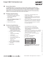
Passport 1000 P1 PoE Cylindrical Lock
General Description
2
Hardware Specifications
3
An ANSI/BHMA Grade 1 lock utilizing Power over Ethernet (PoE) technology, the Passport 1000 P1
provides a cost-effective, future-proof solution for campuses. Featuring multiCLASS SE
®
Technology
from HID Global
®
, it provides simultaneous support for multiple credentials and offers an easy migration
path to higher security credentials and mobile access. Recognized for its contribution to sustainable
buildings, the P1 re-uses existing IEEE 802.3af PoE infrastructure, streamlines the installation process,
reduces costs and components, and minimizes power consumption.
• Complete locksets with controller
• Easily retrofits existing Passport 1000
(cylindrical lock) door preps
• ADA Compliant
• Latch 1/2” standard 3/4” throw fire-rated
double doors (optional) (41- prefix)
• Deadlocking latch
• Inside lever retracts latch
• Outside lever is unlocked through access
control credentials only
• Outside lever controlled by any combination of
keypad, magnetic swipe, contactless reader or
mechanical cylinder
• May be used for indoor and outdoor applications
• ANSI/BHMA A156.25 Listed Grade 1 Compliant
Electronic Specifications
4
• Power Requirements: 55VDC, 90mA
• PoE Class 1 Device, as defined by IEEE
802.3af, requires less than 3.84 watts over
structured cabling
• Multiple time zone and holiday access scheduling
• First-in unlock or automatic unlock configuration,
based on specified time schedule
• 2,400 users per lock; 10,000 event audit trail
• Privacy button
• HID
®
multiCLASS SE
®
technology offers
support for the following credentials:
• 2.4 GHz credential compatibility:
• Secure Identity Object
™
(SIO) on
Mobile IDs (Bluetooth Smart)
• 125 kHz credential compatibilty:
• HID Prox
®
• 13.56 MHz credential compatibility:
• iCLASS
®
• iCLASS SE
®
(SIO-enabled)
• iCLASS Seos
®
• SIO on MIFARE
®
Classic
• SIO on MIFARE
®
DESfire
®
EV1
• MIFARE
®
Classic
• DESfire
®
EV1
• NFC-enabled mobile phones
• Magnetic Stripe
*UL testing was conducted on product powered by UL
Listed model 9001GR/AC injector; manufactured by
Microsemi Corp.
Destructive Attack Level 1
Line Security Level 1
Endurance Level 4
Standby Power Level 1
• UL Listed* - UL294 Indoor Use
• CUL Listed - S319: Class 1
• UL 294 Access Control Ratings:
NOTE: A weather-protective gasket is required
for outdoor applications.

4 1-800-810-WIRE • www.sargentlock.com • A8033G
Copyright © 2016, Sargent Manufacturing Company, an ASSA ABLOY Group company. All rights reserved.
Reproductions in whole or in part without express written permission of Sargent Manufacturing Company is prohibited.
04/30/16
Passport 1000 P1 PoE Cylindrical Lock
Installation Wiring
5
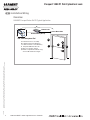
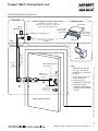
Overview
SARGENT Passport Series PoE P1 Typical Application
LMT: Lock Management Tool
A. PoE frame harness assembly
B. PoE data hinge from McKinney
C. PoE door harness* from McKinney
D. Passport 1000 P1 PoE Lock
E. DPS: Door Position Switch
(Needed on Cylindrical and Exits only)
* Door width determines length
Network Cable
Network Switch (802.3af)
Surface Mount RJ45
A
B
C
E
D

04/30/16
1-800-810-WIRE • www.sargentlock.com • A8033G 5
Copyright © 2016, Sargent Manufacturing Company, an ASSA ABLOY Group company. All rights reserved.
Reproductions in whole or in part without express written permission of Sargent Manufacturing Company is prohibited.
Passport 1000 P1 PoE Cylindrical Lock
Molex-F
Molex-F
Molex-M
Cable: CAT 5e,
26 AWG stranded,
100ohm
RJ45-M
Molex-M
Cable: CAT 5e or higher
24 AWG 100ohm
B-Splice
Crimp Connector
PoE
Lock
Ceiling
Supplied by CI
Ground
Ring Terminal
Secured to Lock
Mounting Plate
Frame-Side
Harness
Assembly
(15' length)
Patch Panel
Cable: CAT 5e or higher
24 AWG
RJ45-F Jack
Approved Software
Certified Integrator (CI) supplies and terminates
the B-Splice connector and the
male RJ45 connector from harness to
end user provided facility cable
Supplied by End User
PoE Switch
PoE Switch is
Terminated to
Earth Ground
Patch Cable
Patch Panel to
PoE Switch
Wiring to TIA/EIA 568-B Standard
A
Notes:
• Connectors go on only
one way. They cannot
be placed in an incorrect
position.
• Do not force and do not
offset connectors
• Be sure they are
completely seated (flush)
• PoE power source
cannot be connected to
a receptacle controlled by
a switch
B
C
D
To building or electrical ground
RJ45-M
Installation Wiring (Continued)
NOTE: TIA/EIA 568-B added
only at lock side

6 1-800-810-WIRE • www.sargentlock.com • A8033G
Copyright © 2016, Sargent Manufacturing Company, an ASSA ABLOY Group company. All rights reserved.
Reproductions in whole or in part without express written permission of Sargent Manufacturing Company is prohibited.
04/30/16
Passport 1000 P1 PoE Cylindrical Lock
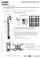
Installation Wiring (Continued)
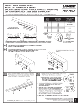
Components and wire harness supplied by McKinney. Suggested installation:
RJ45-M
Molex-M
Cable: CAT 5e or higher
24 AWG 100ohm
B-Splice
Crimp Connector
Ceiling
Supplied by CI
Cut end / ceiling-side PoE harness:
TIA/EIA 568-B Standard Wiring
1
2
3
4
5
6
7
8
Do not confuse pair numbers with pin numbers. A pair number is
used for reference only (eg: 10BaseT Ethernet uses pairs 2 & 3). The
pin numbers indicate actual physical locations on the plug and jack.
Frame-Side
Harness
Assembly
(15' length)
24AWG
Stranded
Drain
Wire for
Earth
Ground in
15' Frame
Harness
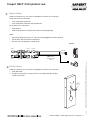
Frame Harness Installation
Hinge side of PoE harness:
A
1. Feed cut end of harness into hole on hinge-side through single access hole.
2. Push one connector back through the hole and feed into the other access hole.
Each of the hinge-side harness connectors should end up threaded through
a different access hole and matched to the same size pin connector from
the door harness:
• 4-pin male molex connector
• 6-pin male molex connector with ground wire
PIN Wire Pair
Number
1 White/Orange 2
2 Orange 2
3 White/Green 3
4 Blue 1
5 White/Blue 1
6 Green 3
7 White/Brown 4
8 Brown 4
1
8
pin
8
1
pin
4-pin M
6-pin M
Frame
PoE Hinge
PoE Data Hinge
Hinge-side harness connectors:
• 4-pin female molex connector
• 6-pin female molex connector with ground wire
Lock-side harness connectors:
• 4-pin female molex connector
• 6-pin female molex connector with ground wire
B
4-pin F
6-pin F
4-pin F
6-pin F

04/30/16
1-800-810-WIRE • www.sargentlock.com • A8033G 7
Copyright © 2016, Sargent Manufacturing Company, an ASSA ABLOY Group company. All rights reserved.
Reproductions in whole or in part without express written permission of Sargent Manufacturing Company is prohibited.
Passport 1000 P1 PoE Cylindrical Lock
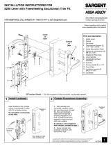
Order of installation may vary. Refer to appropriate sections for instructions.
Hinge-side harness connectors:
• 4-pin male Molex connector
• 6-pin male Molex connector with ground wire
Lock-side harness connectors:
• Ring terminal
• Male RJ45 connector (crimped after cable is fed through door)
Notes:
• Connectors go on only one way. They cannot be plugged to incorrect position.
• Do not force and do not offset connectors.
• Be sure they are completely seated (flush).
Order of installation may vary. Refer to appropriate sections for instructions.
1. Prop door open.
2. Using the ring terminal, carefully route the assembly through the door
channel to the lock.
Hinge Installation
PoE Lock
4-pin F 4-pin M4-pin F
6-pin F 6-pin F 6-pin M
Cable: CAT 5e,
26 AWG stranded,
100ohm
PoE Door Harness
D
C
RJ45-M
PoE
Harness
(Cat 5e)

8 1-800-810-WIRE • www.sargentlock.com • A8033G
Copyright © 2016, Sargent Manufacturing Company, an ASSA ABLOY Group company. All rights reserved.
Reproductions in whole or in part without express written permission of Sargent Manufacturing Company is prohibited.
04/30/16
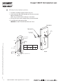
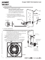
Passport 1000 P1 PoE Cylindrical Lock
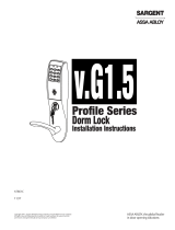
1. Prep door according to proper template (Fig. D1).
2. Insert connector end of DPS through the raceway on the latch
edge of the door (Fig. D2).
Note: Only use collar when installing in a metal door.
3. To insert DPS, push wires through raceway toward lock prep.
4. Push DPS firmly into place by hand.
IMPORTANT: DO NOT TAP SWITCH WITH ANY TOOL.
Horizontal
of Strike
Door Position
Switch Hole
Vertical
of Strike
Dim 2
(See template)
Dim 1
Fig. D1
Wood Frame Metal Frame
Dim 1
3/8” 3/4”
Strike for Cylindrical Lock
Collar is used only
with metal doors.
Door Position
Switch (DPS)
Inside of Door
Fig. D2
Dim 1
DPS (Door Position Switch) Installation
E
DPS
Harness

04/30/16
1-800-810-WIRE • www.sargentlock.com • A8033G 9
Copyright © 2016, Sargent Manufacturing Company, an ASSA ABLOY Group company. All rights reserved.
Reproductions in whole or in part without express written permission of Sargent Manufacturing Company is prohibited.
Passport 1000 P1 PoE Cylindrical Lock
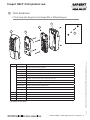
P1 PoE Lock with Magnetic Card Swipe With or Without Keypad
Parts Breakdown
6
1
2
3
4
5
ITEM No. PART No. DESCRIPTION
1 52-3583-[finish] Outside Escutcheon Assemby, mag stripe
52-3582-[finish] Outside Escutcheon Assemby, mag stripe and Keypad (shown)
52-4244-[finish] Outside Escutcheon Assemby, Mag Swipe, Keypad, and HID 125 kHz Prox
52-4759-[finish] Outside Escutcheon Assemby, iCLASS, keypad, mag stripe, Prox, smart card (MIFARE, DESFIRE)
52-4777-[finish] Outside Escutcheon Assemby, iCLASS, mag stripe, Prox, smart card (MIFARE, DESFIRE)
52-4787-[finish] Outside Escutcheon Assemby, FeliCa, keypad, mag stripe, Prox
52-4788-[finish] Outside Escutcheon Assemby, FeliCa, mag stripe, Prox
52-4894-[finish]* Outside Escutcheon Assemby, Standard Reader and Keypad
52-4895-[finish]* Outside Escutcheon Assemby, Standard Reader
52-4896-[finish]* Outside Escutcheon Assemby, Felica Reader and Keypad
52-4897-[finish]* Outside Escutcheon Assemby, Felica Reader
2
52-4779 Mounting Plate Assembly
3 52-4940 PoE Controller Assembly
4 52-4776-[finish] Inside Escutcheon Assembly with Privacy Button
5 52-5373 Door Position Switch Kit
*Bluetooth
®
Smart option

10 1-800-810-WIRE • www.sargentlock.com • A8033G
Copyright © 2016, Sargent Manufacturing Company, an ASSA ABLOY Group company. All rights reserved.
Reproductions in whole or in part without express written permission of Sargent Manufacturing Company is prohibited.
04/30/16
Passport 1000 P1 PoE Cylindrical Lock
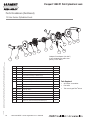
10 Line Series Cylindrical Lock
Parts Breakdown (Continued)
ITEM PART No. DESCRIPTION REQ’D
1 --- Outside Lever (Reference Catalog for Available Styles) 1
2 10-0043 Lever Retainer Key (In Screw Pack 10-2052) 1
3 --- Cylinder Assembly (Reference Catalog for Available Cylinders) 1
4 --- Rose (Reference Catalog for Avalable Styles) 2
5 10-0792 Spacer Bushing 2
6 10-3049 Outside Rose Spring Assembly 1
7 10-3449 Lockbody Assembly 10G77 - Standard Cylinder 1
10-3450 Lockbody - LFIC 1
10-3451 Lockbody - SFIC 1
7a 52-4844 Lockbody Harness 1
8 10-0847 Adapter Plate/Spacer (*Only Included With 1-3/8” Thick Doors) 1
9 10-3192 Latch Assembly 1
10 10-2052 Screw Pack 2
11 10-3048 Inside Rose Spring Assembly 1
12 --- Inside Lever (Reference Catalog for Available Styles) 1
1
2
3
4
5
6
7
11
5
4
12
9
10
8
*
*Adapter Plate/Spacer (10-0847)
is only shipped with orders that
specify 1-3/8” doors.
Tools Required:
• #2 Phillips screwdriver
• Flat head
• T20 security pin Torx
®
driver
7a

04/30/16
1-800-810-WIRE • www.sargentlock.com • A8033G 11
Copyright © 2016, Sargent Manufacturing Company, an ASSA ABLOY Group company. All rights reserved.
Reproductions in whole or in part without express written permission of Sargent Manufacturing Company is prohibited.
Passport 1000 P1 PoE Cylindrical Lock
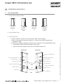
1 Door Preparation
Installation Instructions
7
Left Hand
Hinges Left.
Open Inward.
“LH”
Left Hand
Reverse Bevel
Hinges Left.
Open Outward
“LHRB”
Right Hand
Hinges Right.
Open Inward.
“RH”
Right Hand
Reverse Bevel
Hinges Right.
Open Outward.
“RHRB”
A. Verify Hand and Bevel of Door
B. Verify Product Label
C. Door Preparation
• Prior to installation, all holes must be free of burrs, debris and sharp edges.
• If doors are not properly reinforced per ANSI115.2, commercially available reinforcements
should be installed.
• Prepare door according to appropriate template, (refer to website www.intelligentopenings.com):
• Field template: A8066 with DPS and A8067 without DPS.
• Door manufacturers templates: 4652 with DPS and 4658 without DPS.
Outside of Door
Inside of Door
Door
Position
Switch
Latch
Front
and Hole
Escutcheon Through Bolt Holes
Inside Mouthing Plate Holes
Controller Wire Hole
Wire Run Channel
Lock Body Through Bolt Hoes
Alignment Notches
Lock Body Prep
Escutcheon Through Bolt Holes
Controller Wire Hole
Lockbody Through Bolt Holes
Alignment Notches
Lock Body Prep
Fig. 1
Raceway for PoE
Raceway for PoE

12 1-800-810-WIRE • www.sargentlock.com • A8033G
Copyright © 2016, Sargent Manufacturing Company, an ASSA ABLOY Group company. All rights reserved.
Reproductions in whole or in part without express written permission of Sargent Manufacturing Company is prohibited.
04/30/16
Passport 1000 P1 PoE Cylindrical Lock
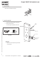
2 Install Strike
Install strike in the door frame (Fig.2).
Fig. 2
3 Install Latch Bolt
1. Install latch with beveled bolt facing strike.
2. Attach with two screws.
DO NOT tighten completely at this time.
Outside of Door
Fig. 3
Latch Assembly
(2) #8-32 x 3/4”
Combination
Screws
DPS Cable
PoE
Harness
(Cat 5e)
IMPORTANT: Latch bevel must match door bevel and
deadlocking latch must stop on strike when door is closed.
Deadlocking Latch
Strike
Fig. 3B Detail
IMPORTANT:
• Door must remain open during installation.
Use door stop.

04/30/16
1-800-810-WIRE • www.sargentlock.com • A8033G 13
Copyright © 2016, Sargent Manufacturing Company, an ASSA ABLOY Group company. All rights reserved.
Reproductions in whole or in part without express written permission of Sargent Manufacturing Company is prohibited.
Passport 1000 P1 PoE Cylindrical Lock
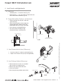
4
Lock Presets and Adjustments
A. Lock Preset
• Lockbody holes – 12 and 6 o’clock (Fig. 5A).
• Door thickness – 1-3/4” thick. Refer to adjustments be-
low for other door conditions (Fig. 4B).
B. Through-Bolt and Door Thickness and Adjustment
• Remove outside lever (Fig 4A), scalp and
spacer bushing.
• Rotate mounting plate to either align with
through-bolt holes in door or adjust for
proper door thicknesses (Fig. 4A and 4B).
• See markings on through-bolt post.
• Re-install spacer bushing (to align
with back of lever), scalp and lever.
Fig. 4A
Lock Body Holes
Rotate to match
lock body holes in door.
1-3/4” Thick Doors
2” Thick Doors
Fig. 4B Detail
1. Insert key, rotate 45° clockwise and hold (Fig. 4C).
2. Depress lever retainer with push pin tool (provided).
Fig. 4C
Cylinder
C. How To Remove Outside Lever (If Necessary)
Cylinder Retainer
Outside Lever
Key
1. With outside lever in hand, use standard
pliers to pull out cylinder retainer.
2. Remove key and cylinder from lever.
3. Insert new cylinder.
4. Secure by pressing cylinder retainer flush.
D. How To Change Cylinder (If Necessary)
Fig. 4D

14 1-800-810-WIRE • www.sargentlock.com • A8033G
Copyright © 2016, Sargent Manufacturing Company, an ASSA ABLOY Group company. All rights reserved.
Reproductions in whole or in part without express written permission of Sargent Manufacturing Company is prohibited.
04/30/16
Passport 1000 P1 PoE Cylindrical Lock
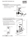
5
Install Lock Body
1. Feed wires followed by the lockbody from
outside of door through the lockbody hole (Fig. 5A).
2. Lockbody must engage both the latchbolt unit prongs
and tail piece (Fig. 5B).
6
Secure Lock To Door
Fig. 5B Detail
Wire Harness
(From Lock Body)
Cylindrical Lock Body
and Outside Trim
Wire Harness
(From Lockbody)
Put top flat head screw
through ground ring
terminal and tighten
down
(2) #10-32 x 1-1/4”
Flat Head Machine
Screws (to secure
outer spring housing)
Spring housing
assembly
Fig. 6A
IMPORTANT: If lock is being installed as a retrofit;
(replacing an existing P1 product), remove the
DPS wires and connector (Fig. 5A) by simply
severing the wires as indicated* (see arrow).
If this is a new lock being installed for the first
time, DO NOT REMOVE wires and connector.
Fig. 5A
Cut wires
here*
DPS
Cable
PoE
Harness
(Cat 5e)
1. Feed wire and connector:
• For wood door, feed connectors and wires through the door
and up the wire run channel (Fig. 6A).
• For metal door (not shown), feed connectors and wires into
the lockbody hole and out the controller hole.
2. Position ground lug between (top) #10-32x1-1/4”
through-bolt and rose assembly (Fig. 6A).
NOTE: Proper placement of ground wire (Fig. 6B) will prevent
pinching/damage to the ground wire.
3. Secure rose assembly with (2) #10-32x1-1/4” through-bolts.
4. Secure latch by fully tightening (2) #6 x 3/4” self-tapping
screws (refer to previous section 3 - Install Latchbolt).
Fig. 6B Detail

04/30/16
1-800-810-WIRE • www.sargentlock.com • A8033G 15
Copyright © 2016, Sargent Manufacturing Company, an ASSA ABLOY Group company. All rights reserved.
Reproductions in whole or in part without express written permission of Sargent Manufacturing Company is prohibited.
Passport 1000 P1 PoE Cylindrical Lock
7
Assemble Inside Trim
1. Verify spacer bushing is inserted horizontally and aligned
with lever (Fig. 7).
2. Place rose (scalp) over shaft of lock body against
surface of door; hand-tighten, turning clockwise.
3. Attach lever. Push until engaged.
Fig. 7
Inside of door
Spacer Bushing
Rose (Scalp)
DPS (Door Position Switch)
Inside Lever
8
Install Wire Cover Plate (Wood Door Only)
1. Position the wire cover plate above the rose and covering
the wire channel. Mark the hole positions.
2. Ensure stamped side of plate is against the door.
3. Drill (2) 3/32” diameter by 1/2” deep holes (Fig. 8A).
4. Cover wires with cover plate by securing plate to door
directly above rose using two (2) #6 x 1/2” flat head security
torx wood screws (Fig. 8A).
Note: Tuck wires and ferrite in hole at top of wire channel
(Fig. 9A). Position lower edge of cover plate against the rose
to ensure no wires are visible and make sure the plate is
oriented correctly (Fig. 8B).
Fig. 8B Detail
This Side Down
Back Side of
Wire Cover Plate
PoE Harness from Hinge
(with ground wire)
Inside of door
Wire Cover
Fig. 8A
(2) #6 x 1/2”
Flat Head Security
Torx Wood Screws

16 1-800-810-WIRE • www.sargentlock.com • A8033G
Copyright © 2016, Sargent Manufacturing Company, an ASSA ABLOY Group company. All rights reserved.
Reproductions in whole or in part without express written permission of Sargent Manufacturing Company is prohibited.
04/30/16
Passport 1000 P1 PoE Cylindrical Lock
Note: Gasket optional, for non-fire rated doors only.
For non-fire rated door applications, an optional gasket
(Part number 52-0782) may be used as a weather seal
between the escutcheon and the outside door surface.
Peel off adhesive backing and attach to
(outside) escutcheon.
1. Position the outside escutcheon, aligning the posts
with the door prep (Fig. 9).
2. Feed reader cable through opening.
9
Install Gasket (Optional) and Install Outside Escutcheon
Outside
Escutcheon
Outside of Door
Fig. 9
Gasket
Reader
Cable
10
Mounting Plate Assembly
1. On the inside of the door, position the
mounting plate over the indicated holes.
2. Feed reader, ground ring terminal and DPS
cables through central opening on mounting
plate (Fig. 10).
3. Route PoE Harness through alternate open-
ing (to the right of the central opening).
4. Route ground ring terminal from lock body
through bottom of mounting plate and
attach to bottom left corner using (1)
#8-32 x 1-7/8” flat head machine screw.
5. Insert other three #8-32 x 1-7/8” flat head
machine screws and tighten, fastening the
outside escutcheon to the door (Fig. 10).
(4) #8 - 32 x 1-7/8” Flat
Head Machine Screws
Mounting Plate
(2) #8 - 3/8” flat head
Wood Screws
Fig. 10
Ground
Lugs
IMPORTANT: If the following step is skipped, the product
will not be UL-compliant:
6. Attach two (2) #8 x 3/8” flat head wood screws for
wood doors or (2) #8-32 x 3/8” flat head machine
screws for metal doors (Fig. 10).
PoE
Harness

04/30/16
1-800-810-WIRE • www.sargentlock.com • A8033G 17
Copyright © 2016, Sargent Manufacturing Company, an ASSA ABLOY Group company. All rights reserved.
Reproductions in whole or in part without express written permission of Sargent Manufacturing Company is prohibited.
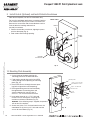
Passport 1000 P1 PoE Cylindrical Lock
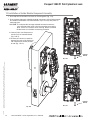
11 Installation of Connectors
Secure Mounting Plate
IMPORTANT: Do not run wires through bottom hole in plate (Fig. 11A)
- it will damage wires and the controller connector. Route wires around
flange, do not route wires through the flange hole (Fig. 11A).
C. Secure the 24-pin card reader connector (Fig. 11A).
D. Crimp* RJ45 to Cat 5e cable from hinge (Fig. 11B).
*For more detail, refer to section (5) ‘Installation Wiring’,
“A - Frame Harness Installation”.
TIA/EIA 568-B Standard Wiring
1
2
3
4
5
6
7
8
Do not confuse pair numbers with pin numbers. A pair number is
used for reference only (eg: 10BaseT Ethernet uses pairs 2 & 3). The
pin numbers indicate actual physical locations on the plug and jack.
PIN Wire Pair
Number
1 White/Orange 2
2 Orange 2
3 White/Green 3
4 Blue 1
5 White/Blue 1
6 Green 3
7 White/Brown 4
8 Brown 4
Fig. 11B
1
8
pin
8
1
pin
Ground
Lugs
Lock
Body
(10-pin)
Reader
(24-pin)
Board-to-Board
Connector
Fig. 11A
A
B
C
DPS (4-pin)
Secure the following connectors to their respective terminals (Fig. 11A):
A. Secure the 4-pin DPS connector.
B. Secure the 10-pin lock body assembly connector.
CAUTION - Do not touch or allow debris to enter connector contacts.
1. Tuck excess cable into wire hole on inside of door.
2. Secure the mounting assembly while ensuring
proper alignment of outside reader and fully tight-
en the (2) throughbolts on the inside of the door to
secure the reader and plate to the door.
Crimp* to RJ45-M
Connector
Cat 5e cable
from hinge
RJ45-M
D

18 1-800-810-WIRE • www.sargentlock.com • A8033G
Copyright © 2016, Sargent Manufacturing Company, an ASSA ABLOY Group company. All rights reserved.
Reproductions in whole or in part without express written permission of Sargent Manufacturing Company is prohibited.
04/30/16
Passport 1000 P1 PoE Cylindrical Lock
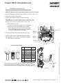
12
Installation of Inside Module Component Assembly
1. Insert top tabs of controller into slots on mounting plate (Fig. 12A).
2. Ensure proper alignment of board-to-board connectors while pivoting bottom
of controller toward door until tab on bottom snaps securely into place on
mounting plate.
CAUTION: To avoid possible damage to board-to-board connectors,
care should be taken when securing controller to mounting
plate. If there is resistance when securing, detach controller
to determine cause before re-attaching controller.
Fig. 12A
Fig. 12B
Coin Cell
Pull Tab
Fig. 12C
Coin Cell
Pull Tab
3. Connect RJ45 male Connector to
female RJ45 on controller board
(Fig. 12B, C).
4. Remove pull tab from its position
beneath the coin cell by pulling on
tab in direction of arrows printed
on tab (Fig. 12B, C).

04/30/16
1-800-810-WIRE • www.sargentlock.com • A8033G 19
Copyright © 2016, Sargent Manufacturing Company, an ASSA ABLOY Group company. All rights reserved.
Reproductions in whole or in part without express written permission of Sargent Manufacturing Company is prohibited.
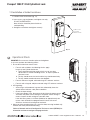
Passport 1000 P1 PoE Cylindrical Lock
(2) #8-32 x 1/2”
Secure Torx
Machine Screws
1. Position inside escutcheon (Fig. 13).
2. Insert screws, top and bottom, and tighten securely.
DO NOT OVERTIGHTEN.
Note: All wires should be placed inside to
avoid pinching.
3. Straighten escutcheon and tighten securely.
13
Installation of Inside Escutcheon
Fig. 13
Operational Check
8
IMPORTANT: Be sure to test functions prior to closing door.
In all cases, perform the following checks:
1. Ensure that inside lever retracts latch.
• For units with cylinders, the following checks apply:
Insert key into cylinder and rotate:
a. There should be no friction against lock case or any other
obstructions. If friction or binding occurs, re-adjust cylinder to
eliminate issues.
b. The key should retract the latch and the key should rotate freely.
c. The key should extend and retract the deadbolt.
• For units without a keypad, add card using LCT software* and test.
• For units with a keypad, add pin and card using LCT software* and test.
2. LED signaling:
• After using a valid credential, a green flash followed by three fast
amber flashes indicates a low power condition.
• Check the input voltage.
• If the input voltage is low, disconnect the lock from the power source
and check the power source voltage. If the power source voltage is
correct, inspect the lock wiring for a possible short.
If the lock loses power, it will flash rapid blue for approximately one
minute. Lock will default to programmed fail safe or fail secure.
After that, the lock will no longer be functional.
3. When you have completed the tests, close the door, ensuring latchbolt fully
extends into strike plate without binding.
*Refer to Network and Lock Configuration Tool user manual (WFMN1) for
information on how to configure and program locks.

SARGENT Manufacturing
100 Sargent Drive
New Haven, CT 06511 USA
800-810-WIRE (9473) • www.sargentlock.com
HID and iCLASS are registered trademarks of HID Global Corporation.
Founded in the early 1800s, SARGENT
®
is a market leader in locksets, cylinders, door closers, exit devices,
electro-mechanical products and access control systems for new construction, renovation, and replacement applications.
The company’s customer base includes commercial construction, institutional, and industrial markets.
Copyright © 2016, Sargent Manufacturing Company, an ASSA ABLOY Group company. All rights reserved.
Reproduction in whole or in part without the express written permission of Sargent Manufacturing Company is prohibited.
ASSA ABLOY is the global leader in door opening solutions, dedicated to
satisfying end-user needs for security, safety and convenience.
A8033G -04/16
-
 1
1
-
 2
2
-
 3
3
-
 4
4
-
 5
5
-
 6
6
-
 7
7
-
 8
8
-
 9
9
-
 10
10
-
 11
11
-
 12
12
-
 13
13
-
 14
14
-
 15
15
-
 16
16
-
 17
17
-
 18
18
-
 19
19
-
 20
20


Sargent P2 PASSPORT 1000 Installation Instructions Manual
- Category
- Security door controllers
- Type
- Installation Instructions Manual
Ask a question and I''ll find the answer in the document
Finding information in a document is now easier with AI
Related papers
-
 Sargent P2 PASSPORT 1000 Installation Instructions Manual
-
 Sargent P2 PASSPORT 1000 Installation Instructions Manual
-
 Sargent PASSPORT 1000 Exit Device Installation Instructions Manual
-
 Sargent P2 PASSPORT 1000 Specification
-
 Sargent 1431 series Installation Instructions Manual
-
 Sargent P2 PASSPORT 1000 Installation Instructions Manual
-
 Sargent POWERGLIDE 281 Installation guide
-
Assa Abloy Passport 1000 P2 User manual
-
 Sargent 8200 Installation guide
-
 Sargent Profile Series Installation Instructions Manual


Other documents
-
Yale All-in-One Owner's manual
-
-
-
 Manital 190FR5PAFB Installation guide
-
-
Lennox iComfort Thermostat Mag-Mount (12X99) Installation guide
-
-
-
BMC Trailsync Replacement Instructions Manual
-
