Assa Abloy Lockwood 3579 Series Mounting instructions

Type
Mounting instructions

Assa Abloy Lockwood 3579 Series is a versatile mortice lock designed to suit a wide range of applications, including commercial, residential, and industrial settings. With its adjustable backset and multiple handing options, it can be easily customized to fit different door types and requirements. The lock features a single action escape mechanism, allowing for quick and easy egress in emergency situations. It also has the flexibility to be used as a vestibule lock with a single action escape feature or as a combination lock with both handles capable of being locked.

Assa Abloy Lockwood 3579 Series is a versatile mortice lock designed to suit a wide range of applications, including commercial, residential, and industrial settings. With its adjustable backset and multiple handing options, it can be easily customized to fit different door types and requirements. The lock features a single action escape mechanism, allowing for quick and easy egress in emergency situations. It also has the flexibility to be used as a vestibule lock with a single action escape feature or as a combination lock with both handles capable of being locked.

3579 SERIES MORTICE LOCK
MOUNTING INSTRUCTIONS
P/No. 3579-5121 0617
RIGHT - HAND DOOR
LEFT - HAND DOOR
OUTSIDE
DOOR OPENING
IN
OUTSIDE
DOOR OPENING
OUT
OUTSIDE
DOOR OPENING
OUT
OUTSIDE
DOOR OPENING
IN
1
4
2
SETTING LOCK STATUS
SETTING LOCK STATUS
HAND OF DOOR ACCORDING TO ENGLISH PRACTICE
Determine hand of lock required from hand of door chart above.
All Lockwood 3579 Series Mortice Locks are mounted in accordance
with these instructions. Locks may or may not have cylinders,
lever handles, turn knob or emergency button. Disregard instructions
referring to the features not required.
Important : Before drilling door, ensure correct hand is being installed.
NOTE: CASE DOES NOT need to be opened, to change HAND or
FUNCTION of LOCK.
HANDING OF LOCK
Determine hand of lock required from above hand of door chart.
Rotate bolt head to suit latching direction.
Ensure lock is in UNLOCKED position.
To UNLOCK (if required), using a small screwdriver, lever out Cylinder Hole
Plug where fitted and lift snib using the screwdriver.
SNIB CAM
Rotation of the Snib Cam hands the lock. Use a small screwdriver to rotate
cam if required.
Combination locks
(Both handles can be locked) DOT in the up position.
Vestibule Locks
With single action escape feature. DOT to be DOWN on ESCAPE
side and UP on LOCKABLE side.
Establish which side the adaptor is to be located, lever out Cylinder hole plug
where fitted.
PUT LOCK IN LOCKED POSITION, as shown in Step 1.
Insert Adaptor into lock body with TOP of Turn Knob Cam point away from front
of lock body. Ensure Turn Knob Cam is engaged in yoke of snib as shown.
Place retainer pin through front plate to retain adaptor to lock. Ensure pin is
flush with front plate
To de-activate KICK-OFF function, ensure the lock is unlocked, then
remove the KICK-OFF screw as shown. Rotate screw in the direction of
the arrow as the screw is left hand thread.
LOCKABLE
LOCKABLE
VESTIBULE
RIGHT HAND
DOOR
LOCKABLE
ESCAPE
VESTIBULE
LEFT HAND
DOOR
ESCAPE LOCKABLE
3
SETTING KICK-OFF FUNCTION
YOKE
TURN KNOB CAM
TEAR HERE
COMBINATION
TURN KNOB ADAPTORS
UNLOCKED
LOCKED
TEAR HERE
ENSURE LOCK IS REMOVED FROM MORTICE
BEFORE DRILLING HOLES
DO NOT DRILL HOLES RIGHT THROUGH DOOR
TO PREVENT POSSIBLE DAMAGE TO DOOR FACE
ENSURE LOCK IS REMOVED FROM MORTICE
BEFORE DRILLING HOLES
DO NOT DRILL HOLES RIGHT THROUGH DOOR
TO PREVENT POSSIBLE DAMAGE TO DOOR FACE
EDGE A
60mm BACKSET
89mm BACKSET
127mm BACKSET
1 HOLE - 22mm DIA.
FOR SPINDLE
FOLD LINE ALONG EDGE OF DOOR 60mm BACKSET
1 HOLE - 22mm DIA.
FOR TURN KNOB
2 HOLES - 20mm DIA.
FOR CYLINDER
7 HOLES
ø22mm x
90mm DEEP
(for 60mm backset)
MORTICE
CENTRELINE
1 HOLE - 22mm DIA.
FOR SPINDLE
1 HOLE - 22mm DIA.
FOR TURN KNOB
2 HOLES - 20mm DIA.
FOR CYLINDER
60mm BACKSET
89mm BACKSET
127mm BACKSET
65
DOOR PREPARATION
DOOR PREPARATION
Establish height that lockset will be mounted on door and mark centreline of
door thickness on door edge.
Place Mortice Template on door and align centreline on template with centreline
on door. Secure with sticky tape.
Mark and drill mortice to suit mortice lock depth (90mm).
Ease out mortice cavity where necessary. Clean out mortice before inserting lock.
Insert lock in mortice with Cover Plate on and scribe around Cover Plate for size of
recess, ensuring that no foreign matter finds it way into the lock mechanism.
Remove lock from mortice and chisel recess 4mm deep to receive both front
and cover plate. Cover plate must be flush with edge of door.
Ensure lock is removed from mortice cavity. Fold template along backset fold
line. Align EDGE A with bottom of cover plate recess. Establish holes required to
suit lock function, mark hole centres accurately, drill and clean holes.
Drill furniture holes as required.
Fasten mortice lock into door using mounting screws provided.
87
LOCKS WITH CYLINDERS
Place lock in mortice and insert cylinder.
Secure cylinder with retainer pin, ensuring pin is flush with front plate.
Install Cover plate and secure with 2 M4 screws provided to lock body.
LOCKS WITHOUT CYLINDERS
Install Cover plate and secure with 2 M4 screws provided to lock body.
Strike
Strike
Box
Jamb
P
L
E
A
S
E
R
E
C
Y
C
L
E
T
H
I
S
P
A
C
K
A
G
I
N
G
Mark out door frame for strike.
Mortice door frame for strike box and strike. Bolt
recess to be 15mm deep in door frame.
Screw strike and strike box to the door frame with
two screws supplied with mortice lock.
All locks are supplied with spindles.
Insert spindle(s) into lock, as required.
Assemble furniture as required. Ensure furniture is
not over-tightened.
Mark and cut connecting bar as shown.
Turn knob to be in the vertical position when UNLOCKED.
LOCKS WITH TURNKNOBS
9
LOCKS WITH SPINDLES
10
MOUNTING STRIKE
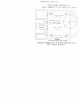
THIS IS A COMMON TEMPLATE FOR
3560 SERIES MORTICE LOCKS.
BEFORE DRILLING HOLES, CHECK
THAT THEY WILL SUIT LOCKSET
TO BE FITTED.
ENSURE LOCK IS REMOVED FROM MORTICE
HOLE
22mm DIA
FOR SPINDLE
EDGE A
2 HOLES
20mm DIA
FOR CYLINDER
60 mm Backset
Centreline
Mortice template
Door
FOLD LINE ALONG EDGE OF DOOR 60mm BACKSET
Mortice
Centreline
IMPORTANT - To prevent damage to the door face from
drill "breakthrough", MARK BOTH SIDES OF DOOR &
DRILL HOLES HALF WAY THROUGH EACH SIDE
LATCHING OR
LOCKING TURNKNOB
EMERGENCY TURNKNOB
FUNCTION
IMPORTANT :
Attach spindle spring to rear
of spindle before assembling.
The supplied spindles must be
used for SEEPL.
Cover
plate
(Square)
Cover
plate
(Round)
Cover plate
(Square)
LOCKS AND CYLINDERS
Cylinder
retainer
pin
Cylinder
assembly
Cover plate
(Round)
ASSA ABLOY Australia Pty Limited, 235 Huntingdale Rd, Oakleigh, VIC 3166 ABN 90 086 451 907 ©2017
The global leader in door opening solutions
  • Page 1 1
  • Page 2 2

Assa Abloy Lockwood 3579 Series Mounting instructions

Type
Mounting instructions

Assa Abloy Lockwood 3579 Series is a versatile mortice lock designed to suit a wide range of applications, including commercial, residential, and industrial settings. With its adjustable backset and multiple handing options, it can be easily customized to fit different door types and requirements. The lock features a single action escape mechanism, allowing for quick and easy egress in emergency situations. It also has the flexibility to be used as a vestibule lock with a single action escape feature or as a combination lock with both handles capable of being locked.

Ask a question and I''ll find the answer in the document

Finding information in a document is now easier with AI