Page is loading ...

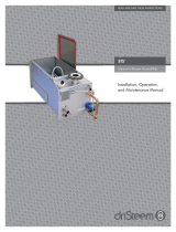
200 series
reverse-osmosis systems
Installation, Operation,
and Maintenance Manual
WATER TREATMENT
READ AND SAVE THESE INSTRUCTIONS

ii
DRISTEEM RO 200 SYSTEM WATER TREATMENT SYSTEMS INSTALLATION, OPERATION, AND MAINTENANCE MANUAL
WARNINGS AND CAUTIONS
WARNING CAUTION
Indicates a hazardous situation that could result in death or
serious injury if instructions are not followed.
Indicates a hazardous situation that could result in damage to or
destruction of property if instructions are not followed.
mc_051508_1145
WARNING
Attention installer
Read this manual before installing, and leave this manual with product owner. This product must be installed by qualifi ed
HVAC and electrical contractors and in compliance with local, state, federal, and governing codes. Improper installation
can cause property damage, severe personal injury, or death as a result of electric shock, burns, or fi re.
DriSteem Technical Support: 800-328-4447
Read all warnings and instructions
Read this manual before performing service or maintenance procedures on any part of the system. Failure to follow all
warnings and instructions could produce the hazardous situations described, resulting in property damage, personal
injury, or death.
Failure to follow the instructions in this manual can cause moisture to accumulate, which can cause bacteria and mold
growth or dripping water into building spaces. Dripping water can cause property damage; bacteria and mold growth
can cause illness.
If the IOM is missing, go to www.dristeem.com to download a replacement.
Shut down the energy source
Before performing service or maintenance procedures on any part of the system, verify that all energy sources are off.
Failure to shut down the energy source could result in fi re, explosion, electrical shock, and other hazardous conditions.
These hazardous conditions could cause property damage, personal injury, or death.
Contact with energized circuits can cause property damage, severe personal injury or death as a result of electrical
shock or fi re. Do not remove electrical panel cover/door or access panels until electrical power is disconnected.
Follow the shutdown procedure in th
e system IOM before performing service or maintenance procedures on any part of
the system.
Warnings and cautions

iii
DRISTEEM RO 200 SYSTEM WATER TREATMENT SYSTEMS INSTALLATION, OPERATION, AND MAINTENANCE MANUAL
Warnings and cautions
Fill in the following information for your records
Date of purchase
___________________________________________________________________________________________________________
Customer's name
___________________________________________________________________________________________________________
Model number
___________________________________________________________________________________________________________
Serial number
___________________________________________________________________________________________________________
WARNING
Disconnect electrical power
Disconnect electrical power before installing supply wiring or performing service or maintenance procedures on any
part of the humidifi cation system. Failure to disconnect electrical power could result in fi re, electrical shock, and other
hazardous conditions. These hazardous conditions could cause property damage, personal injury, or death.
Contact with energized circuits can cause property damage, severe personal injury, or death as a result of electrical shock
or fi re. Do not remove RO system electrical panel cover, heater terminal cover, or subpanel access panels until electrical
power is disconnected.
Follow the shutdown procedure in this manual before performing service or maintenance procedures on any part of the
system.
mc_052410_1510
Electric shock hazard
If the RO system starts up responding to a call for humidity during maintenance, severe bodily injury or death from
electric shock could occur. To prevent such start-up, follow the procedure below before performing service or maintenance
procedures on this RO system (after the tank has cooled down and drained):
1. Use Vapor-logic
®
keypad/display to change control mode to Standby.
2. Shut off all electrical power to the RO system using fi eld-installed fused disconnect, and lock all power disconnect
switches in OFF position.
3. Close fi eld-installed manual water supply shut-off valve.
mc_050808_1540

iv
DRISTEEM RO 200 SYSTEM WATER TREATMENT SYSTEMS INSTALLATION, OPERATION, AND MAINTENANCE MANUAL
WARNINGS AND CAUTIONS . . . . . . . . . . . . . . . . . . . . . . . . . . . . . . . . . . . . . . . . . . . . . . . . ii
OVERVIEW. . . . . . . . . . . . . . . . . . . . . . . . . . . . . . . . . . . . . . . . . . . . . . . . . . . . . . . . . . . . . . 2
System specifications . . . . . . . . . . . . . . . . . . . . . . . . . . . . . . . . . . . . 2
Controller . . . . . . . . . . . . . . . . . . . . . . . . . . . . . . . . . . . . . . . . . . . . 4
RO supply water requirements . . . . . . . . . . . . . . . . . . . . . . . . . . . . . 5
Flow schematic . . . . . . . . . . . . . . . . . . . . . . . . . . . . . . . . . . . . . . . . 6
Component identification . . . . . . . . . . . . . . . . . . . . . . . . . . . . . . . . . 8
INSTALLATION . . . . . . . . . . . . . . . . . . . . . . . . . . . . . . . . . . . . . . . . . . . . . . . . . . . . . . . . . . . 9
OPERATION . . . . . . . . . . . . . . . . . . . . . . . . . . . . . . . . . . . . . . . . . . . . . . . . . . . . . . . . . . . 10
System operation . . . . . . . . . . . . . . . . . . . . . . . . . . . . . . . . . . . . . . 10
Initial system start-up . . . . . . . . . . . . . . . . . . . . . . . . . . . . . . . . . . . 10
System flush . . . . . . . . . . . . . . . . . . . . . . . . . . . . . . . . . . . . . . 10
Normal operations . . . . . . . . . . . . . . . . . . . . . . . . . . . . . . . . . . . . 10
Shutdown . . . . . . . . . . . . . . . . . . . . . . . . . . . . . . . . . . . . . . . . . . . 10
Start-up checklist . . . . . . . . . . . . . . . . . . . . . . . . . . . . . . . . . . . . . . 11
Start-up . . . . . . . . . . . . . . . . . . . . . . . . . . . . . . . . . . . . . . . . . . . . 12
Start-up procedure . . . . . . . . . . . . . . . . . . . . . . . . . . . . . . . . . . 12
Test operation . . . . . . . . . . . . . . . . . . . . . . . . . . . . . . . . . . . . . 12
Initial system start-up . . . . . . . . . . . . . . . . . . . . . . . . . . . . . . . . . . . 12
Operating do's and don't's . . . . . . . . . . . . . . . . . . . . . . . . . . . . . . 13
Do . . . . . . . . . . . . . . . . . . . . . . . . . . . . . . . . . . . . . . . . . . . . . . . . 13
Don't . . . . . . . . . . . . . . . . . . . . . . . . . . . . . . . . . . . . . . . . . . . . . . 13
Vapor-logic keypad/display . . . . . . . . . . . . . . . . . . . . . . . . . . . . . . 14
Changing mode . . . . . . . . . . . . . . . . . . . . . . . . . . . . . . . . . . . . . . 15
Controller display activity definitions . . . . . . . . . . . . . . . . . . . . . . . . 15
Test outputs . . . . . . . . . . . . . . . . . . . . . . . . . . . . . . . . . . . . . . . . . . 15
Test run . . . . . . . . . . . . . . . . . . . . . . . . . . . . . . . . . . . . . . . . . . . . 15
Status screen . . . . . . . . . . . . . . . . . . . . . . . . . . . . . . . . . . . . . . 16
Diagnostics and Alarms . . . . . . . . . . . . . . . . . . . . . . . . . . . . . . . . . 17
Modbus, BACnet, LonTalk interoperability . . . . . . . . . . . . . . . . . . . . 18
Table of contents

1
DRISTEEM RO 200 SYSTEM WATER TREATMENT SYSTEMS INSTALLATION, OPERATION, AND MAINTENANCE MANUAL
Table of contents
ATTENTION INSTALLER
Read this manual before installing.
Leave manual with product owner.
DriSteem
®
Technical Support
800-328-4447
Where to find more information
Our website:
The following documents are available on our
web site: www.dristeem.com
• Water Treatment Systems Catalog
• Vapor-logic Controller Installation and
Operation Manual
DriCalc
®
sizing and selection software:
DriCalc, our software for system sizing and
selection, can be ordered at our web site.
Call us at 800-328-4447
Obtaining documents from our web site or
from DriCalc is the quickest way to view our
literature, or we will be happy to mail literature
to you.
Keypad/display and troubleshooting
The Vapor-logic Installation and Operation
Manual, which was shipped with your RO
system, is a comprehensive operation manual.
Refer to it for information about using the
keypad/display and Web interface, and for
troubleshooting information.
Download DriSteem literature
Most DriSteem product manuals are available
our website: www.dristeem.com
MAINTENANCE . . . . . . . . . . . . . . . . . . . . . . . . . . . . . . . . . . . . . . . . . . . . . . . . . . . . . . . .
20
Maintenance information . . . . . . . . . . . . . . . . . . . . . . . . . . . . . . . . 20
Maintenance tips . . . . . . . . . . . . . . . . . . . . . . . . . . . . . . . . . . . . . . 20
When to change sediment and carbon filters . . . . . . . . . . . . . . . . . . 20
Changing cartridge filters . . . . . . . . . . . . . . . . . . . . . . . . . . . . . 20
When to clean or replace membranes . . . . . . . . . . . . . . . . . . . . . . . 21
Replacing membranes . . . . . . . . . . . . . . . . . . . . . . . . . . . . . . . . . . 21
Tools . . . . . . . . . . . . . . . . . . . . . . . . . . . . . . . . . . . . . . . . . . . 21
Procedure . . . . . . . . . . . . . . . . . . . . . . . . . . . . . . . . . . . . . . . . 21
Membrane cleaning in the RO system . . . . . . . . . . . . . . . . . . . . . . . 22
How does it work? . . . . . . . . . . . . . . . . . . . . . . . . . . . . . . . . . . . . 22
Scale cleaning cartridge. . . . . . . . . . . . . . . . . . . . . . . . . . . . . . . . . 22
Cleaning procedure . . . . . . . . . . . . . . . . . . . . . . . . . . . . . . . . . . . . 22
Organic cleaning cartridge . . . . . . . . . . . . . . . . . . . . . . . . . . . . . . 23
Cleaning procedure . . . . . . . . . . . . . . . . . . . . . . . . . . . . . . . . . . . . 23
Storage . . . . . . . . . . . . . . . . . . . . . . . . . . . . . . . . . . . . . . . . . . . . 24
Membrane preservative cartridge . . . . . . . . . . . . . . . . . . . . . . . . . . 24
Preserving procedure . . . . . . . . . . . . . . . . . . . . . . . . . . . . . . . . 24
Flushing out preservative/restart procedure . . . . . . . . . . . . . . . . 24
System monitoring and record keeping . . . . . . . . . . . . . . . . . . . . . . 25
System operating log . . . . . . . . . . . . . . . . . . . . . . . . . . . . . . . . . . . 26
Water quality test strips . . . . . . . . . . . . . . . . . . . . . . . . . . . . . . . . . 27
Water Quality Test Strips Sample Pack . . . . . . . . . . . . . . . . . . . . . . 27
REPLACEMENT PARTS . . . . . . . . . . . . . . . . . . . . . . . . . . . . . . . . . . . . . . . . . . . . . . . . . . . . 28
RO system (Models 201, 202, and 203) . . . . . . . . . . . . . . . . . . . . . 28
Subpanel . . . . . . . . . . . . . . . . . . . . . . . . . . . . . . . . . . . . . . . . . . . 30
Notes . . . . . . . . . . . . . . . . . . . . . . . . . . . . . . . . . . . . . . . . . . . . . . 31
WARRANTY . . . . . . . . . . . . . . . . . . . . . . . . . . . . . . . . . . . . . . . . . . . . . . . . . . . . . . . . . . . 32

2
DRISTEEM RO 200 SYSTEM WATER TREATMENT SYSTEMS INSTALLATION, OPERATION, AND MAINTENANCE MANUAL
System specifi cations
OVERVIEW
NOTES:
1. All systems rated at 50°F (10°C) using 1000 ppm sodium chloride (NaCl)
solution. System capacity decreases signifi cantly with decrease in feed
water temperature.
2. Chlorine requirements for the feed water are:
a. Thin-Film (standard) 0 ppm
3. Feed water must be filtered to a turbidity of less than 1 NTU.
4. System recovery (permeate to concentrate ratio) must be maintained at
the recommended level. A higher than recommended recovery will lead
to a premature fouling of the membrane with a loss of permeate flow and
permeate quality.
5. Recommended minimum clearances if:
– 24" or greater (610 mm) above: 6" (152 mm) left, right and rear and
24" (610 mm) front
– less than 24" (610 mm) above: 6" (152 mm) left and right and 24"
(610 mm) front and rear
Table 2-1:
RO station electrical specifications and weights
Model Hz Motor HP Volts*/Amps Phase/Frequency
Approximate
shipping weight**
Operating
weight**
Noise***
201
60 1/3
110-120
VAC/5.5A
(208-240
VAC/2.8A)
1/60Hz
118 lbs. (54 kg) 142 lbs. (64 kg)
49 dBA min.
58 dBa max.
202 124 lbs. (56 kg) 148 lbs. (67 kg)
203 130 lbs. (59 kg) 154 lbs. (70 kg)
* 115V or 230V must be ordered specifi cally
** Tank bladder pressure = 28 psi, tank full at 50 psi
*** Noise measurements taken 6.5' (2 m) in front of the RO-200 water treatment system.

3
DRISTEEM RO 200 SYSTEM WATER TREATMENT SYSTEMS INSTALLATION, OPERATION, AND MAINTENANCE MANUAL
Table 3-1:
RO station capacities
Model 201 202 203
Rated capacity, permeate
Gallons/minute 0.2 0.4 0.6
Concentrate fl ow (reject)
1
Gallons/minute 0.6 - 1.1 0.7 - 1.2 0.5 - 1.0
Recirc fl ow (adjustable as needed)
1, 2
Gallons/minute 0 - 0.5 0 - 0.5 0 - 0.5
System pressure, psi (pump pressure through membranes) 100 - 150 100 - 150 100 - 150
°F (°C) 50 (10) 50 (10) 50 (10)
Pre-fi lters
Sediment cartridge - 5 micron 1 1 1
Carbon cartridge - 10 micron 2 2 2
Pressure sensor settings
Low pressure (for pump protection) 8 psi 8 psi 8 psi
1.
Reduce concentrate fl ow by the amount of recirc fl ow used to maintain the recommended maximum system level.
2.
Recirc fl ow usage will reduce water but may decrease membrane life.
System specifi cations
OVERVIEW

4
DRISTEEM RO 200 SYSTEM WATER TREATMENT SYSTEMS INSTALLATION, OPERATION, AND MAINTENANCE MANUAL
Static IP addresses
See the Vapor-logic Controller Installation and
Operation Manual shipped with the RO system
for more information about confi guring IP
addresses.
CONTROLLER
The Vapor-logic controller in the RO system provides menus for all RO system
functions, with a Web interface for Ethernet access (see Figure 4-1).
The Vapor-logic Installation and Operation Manual ships with the RO system.
Refer to it for information on using the keypad/display and Web interface, and
for troubleshooting information.
Softkeys
for direct menu access
Navigation buttons
for item selection
System alarms
Tank status
System messages
Mode
KEYPAD/DISPLAY
FIGURE 4-1: VAPOR-LOGIC KEYPAD/DISPLAY AND WEB INTERFACE
Product overview
OVERVIEW

5
DRISTEEM RO 200 SYSTEM WATER TREATMENT SYSTEMS INSTALLATION, OPERATION, AND MAINTENANCE MANUAL
Product overview
OVERVIEW
WEB INTERFACE
RO SUPPLY WATER REQUIREMENTS
Supply water quality is an important component
of DriSteem reverse osmosis system reliability and
maintenance.
Water hardness can increase the reverse osmosis system
maintenance requirements.
To maximize service life and minimize maintenance for
RO systems and downstream equipment, softened water is
required with all DriSteem RO systems.

6
DRISTEEM RO 200 SYSTEM WATER TREATMENT SYSTEMS INSTALLATION, OPERATION, AND MAINTENANCE MANUAL
Flow schematic
OVERVIEW
FIGURE 6-1: FLOW SCHEMATIC
RO200-PIPING

7
DRISTEEM RO 200 SYSTEM WATER TREATMENT SYSTEMS INSTALLATION, OPERATION, AND MAINTENANCE MANUAL
Flow schematic
OVERVIEW
FIGURE 7-1: FLOW SCHEMATIC
RO200-PIPING-1

8
DRISTEEM RO 200 SYSTEM WATER TREATMENT SYSTEMS INSTALLATION, OPERATION, AND MAINTENANCE MANUAL
Component identifi cation
FIGURE 8-1: COMPONENT IDENTIFICATION
Table 8-1:
Component identification
Item Description
1 Vapor-logic keypad/display Power On/Off and status display
2 Inlet solenoid valve Normally closed. Opens when power is applied.
3 Filter pressure sensor
Measure the feed and effl uent pressure of the cartridge fi lters. Pressure difference determines when
cartridge change out is required.
4 Sediment fi lter 5 micron sediment fi lter.
5 Carbon fi lter 10 micron extruded carbon cartridge to remove chlorine and reduce organics from the feed stream.
6 Low pressure sensor Shuts the system down if the inlet pressure is lower than 8 psi (adjustable).
7 High pressure pump and motor Rotary pump and motor to pressurize the incoming water.
8 Membrane modules RO membrane elements housed in stainless steel pressure tubes.
9 System pressure gauges Measure the system (feed) and concentrate (effl uent) pressure of the membrane modules.
10 Concentrate to drain control valve To adjust system pressure. Must not be completely closed when the system is in operation.
11 Concentrate recirc control valve To adjust and maintain adequate fl ow thru membranes
12 Permeate fl ow control valve Monitor permeate water fl ow.
13 TDS monitor Monitors the feed and permeate water quality.
14 Permeate check valve Prevents backfl ow into RO module.
15 Pipe drain Drain assembly. Run to a fl oor drain.
16 Vapor-logic control board The Vapor-logic control board is mounted inside the control cabinet.
10
11
5
4
2
9
7
OVERVIEW
8
16
14
1
6
15
13
12
3

9
DRISTEEM RO 200 SYSTEM WATER TREATMENT SYSTEMS INSTALLATION, OPERATION, AND MAINTENANCE MANUAL
INSTALLATION
Piping and instrumentation arrangement
FIGURE 9-1: FLOW SCHEMATIC WITH A CARTRIDGE DECHLORINATOR
OM-7905

10
DRISTEEM RO 200 SYSTEM WATER TREATMENT SYSTEMS INSTALLATION, OPERATION, AND MAINTENANCE MANUAL
OPERATION
System operation
INITIAL SYSTEM START-UP
SYSTEM FLUSH
Direct permeate discharge to drain for fi rst 30 minutes of operation.
1. Connect the system to the appropriate electrical outlet, 110-120 VAC or
208-240 VAC 1 phase.
2. Ensure all plumbing connections are open to allow flow. Open the
concentrate valve (counterclockwise). Close the recirc valve (clockwise).
Ensure suffi cient pressure (40 psi recommended) is in feed line. If pressure
is less than 8 psi, the low pressure sensor will disallow start-up until
pressure is adequate.
3. Press the power button; the solenoid will open and the unit will start
operating.
4. After water is flowing from the concentrate line, adjust the concentrate
control valve to obtain designated flow for the specific model (see Table
3-2 on page 3).
5. If required, adjust recirc control valve to meet desired flow rates (see
Table 3-2 on page 3).
6. Allow the unit to run for 30 minutes to ensure proper flushing of system.
7. After the flush time is over, press the power button OFF.
8. Redirect the permeate line to the desired location.
NORMAL OPERATIONS
1. Turn the power back ON. After the pump starts, adjust the control valve to
the desired flow/pressure (not to exceed 150 psi).
2. The recirculation valve may now be adjusted to achieve desired
recirculation flow rate, ensuring concentrate flow rate is as specified.
SHUTDOWN
1. Press the power button to shut unit OFF. Close the isolation valve if it is
installed on the feed line.
2. If the unit is to be shut down for more than one week, a membrane
preservative should be used. To accomplish this, perform 30 second flush
using cartridge filter insert (see page 24 for more information). After
30 seconds, press the power button OFF, and close the concentrate valve.
This will hold the preservative in the pressure vessel.
3. When the system is restarted after an extended shutdown, follow initial
system start-up procedures.
FIGURE 10-1: CONTROL VALVES
CAUTION
To prevent concentrate from
precipitating and causing irreversible
fouling of the RO membrane, do not
operate the system with the control
valve completely closed.
CAUTION
Do not exceed recommended
maximum recovery.

11
DRISTEEM RO 200 SYSTEM WATER TREATMENT SYSTEMS INSTALLATION, OPERATION, AND MAINTENANCE MANUAL
OPERATION
Start-up checklist
If an item in the Start-up checklist below does not apply to your system, skip to the next item and continue the process.
☐ Read this manual and all other information that was provided with your system.
☐ Verify that all fi eld wiring is done according to the instructions in this manual and in the unit wiring diagram.
☐ Confi rm that proper grounding and an approved earth ground are provided.
☐ Confi rm that the keypad/display is mounted with its modular cable routed away from high-voltage circuits and
connected to the Display connector on the Vapor-logic board.
☐ Install cartridge fi lter and check for leaks.
☐ Precharge pressurized RO storage tank to 28 psi (195 kPa).
Note: This precharge pressure is for pressurized RO storage tank cut-in and cut-out switch points at 30 and 50 psi
(210 and 345 kPa) respectively.
☐ Turn on the water supply, and confi rm there are no leaks.
☐ Turn on power to the unit, and confi rm the Main menu is displayed on the keypad/display. The display may take
several seconds to appear as the controller powers up.
☐ Confi rm in the Main Menu that the mode is “Auto” and that status is “Idle.”
☐ When “Idle” appears in main menu, confi rm that the inlet pressure is at least 40 psi (276 kPa) on the display.
☐ With suffi cient water available, the system in Auto mode, and the storage tank pressure less than 30 psi (210 kPa),
verify that the pump is activated.
☐ Set perm fl ow and recirc fl ow meter to desired setting.
☐ If you experience diffi culties, have the keypad/display information available along with the serial number and unit
Model, and call DriSteem Technical Support at 800-328-4447.
Note: Instructions on how to properly care for the freeze protect chemical that is shipped with the system is available
on the SDS sheet at www.dristeem.com.
☐ Inspect to insure that no fl exible plumbing lines have been kinked or damaged during installation.
WARNING
Tipping hazard
Before installing the 200 series
reverse-osmosis system, use
supplied leg brackets or lag points
to permanently fi x the system to
the fl oor and/or adjacent building
structure. Failure to install according
to instructions can result in serious
injury or death. See page 10 for
instructions.

12
DRISTEEM RO 200 SYSTEM WATER TREATMENT SYSTEMS INSTALLATION, OPERATION, AND MAINTENANCE MANUAL
OPERATION
START-UP PROCEDURE
Check component installation per the layout shown in Figure 6-1
(depending on your model). After all components are installed and connected
properly:
1. Perform all applicable “Start-up checklist” items on Page 11.
2. Read and follow instructions in the “Operation” section of Vapor-logic
Installation and Operation Manual.
Note: During start-up, do not leave the system unattended.
TEST OPERATION
Using the keypad/display or web interface, place pump station in Auto mode.
Perform the following procedure:
1. If the system has a full RO holding tank, create a call for water by draining
water from the tank until the pressure falls below 30 psi (210 kPa).
2. Monitor system performance, and watch for leaks.
3. If a leak is found:
a. Remove demand signal, and put the system in Standby mode.
b. Tighten any loose connections.
c. Return system to Auto mode.
d. If a leak persists, replace tubing or fi tting that is leaking.
4. Leave system in Auto mode. It will automatically refill the RO holding tank
when pressure falls below 30 psi (210 kPa).
INITIAL SYSTEM START-UP
1. Close the manual valves to both the RO holding tank and all downstream
equipment. Open the manual valve leading to the drain.
2. Open the feed water supply valve.
3. Open the concentrate control valve fully counterclockwise. Close the
recirculation valve.
4. Put the system into 'Auto' mode. Note inlet water pressure must be at least
40 psi (276 kPa).
5. If incoming pressure is too high, an inlet pressure regulator (not included)
may be installed. This should be set at 40 psi (276 kPa).
6. Some fittings may have loosened during shipment. Check for leaks at all
tube fittings and threaded joints.
7. Allow the unit to run for at least 30 minutes to flush the preservative
solution from the system.
Start-up
CAUTION
If the pump chatters loudly, it is
starving for water (cavitating). Turn the
unit OFF immediately to prevent pump
damage. Correct the low pressure
condition before proceeding.
Important
If the system is not in operation within six
months of shipment, it is strongly recommended
to use an organic cleaning cartridge prior
to performing the start-up checklist to ensure
proper operation. See page 11 for
information and part number.
FIGURE 12-1: SOLENOID VALVE INLET
CAUTION
Pump and system performance will be
adversely affected if the feed/suction
line is restricted.

13
DRISTEEM RO 200 SYSTEM WATER TREATMENT SYSTEMS INSTALLATION, OPERATION, AND MAINTENANCE MANUAL
Start-up
1. Once the preservative solution has been flushed from the system, shut
down the system by putting the system into 'Standby' mode on the Vapor-
logic keypad and close the manual valve going to the drain. Open the
manual valves to both the RO storage tank and downstream equipment.
2. Run a ¾" MNPT from the stand pipe drain to an open drain.
3. Put the system back into 'Auto' mode.
4. Adjust the throttle valve to get the specified permeate flow (if applicable).
5. Adjust the concentrate valve and recirculation valve until the specified
permeate flow and recirculation flow are obtained. It may be necessary to
readjust the throttle valve. See Table 3-1.
6. Test the operation of a low pressure sensor by slowly closing the inlet
water supply valve. The unit should shut off after a short 5 second time
delay.
7. Once all the desired flows are set, allow the system to run for
approximately 30 minutes. Then record the performance information using
the system operation data log on page 26. The values recorded at
startup will be important for determining system performance at a later
date.
OPERATING DO'S AND DON'T'S
DO
1. Change the cartridge filters regularly
2. Monitor the system and keep a log daily
3. Run the system, as much as possible, on a continuous basis.
4. Adjust the system recovery to the recommended value
DON'T
1. Permit chlorine in the feed water.
2. Shut down the system for extended periods. If system will be down for
more than one week, treat the system with a membrane preservative. See
page 20 for instructions.
3. Close the throttle valve completely.
4. Operate the system with insufficient feed flow.
CAUTION
Do not operate the system with the
control valve closed.
Important:
By setting the feed pressure as low as possible
to meet the application requirement, the
service life of the pump and RO elements
will be optimized. The system should be run
continuously when possible, rather than go
through frequent start/stop cycles.
OPERATION
CAUTION
Damage to pump
Do not close the valve. Do not operate
the pump below minimum combined
fl ow rate (permeate + concentrate +
recirculating).
CAUTION
Confi rm all lines are connected before
plugging in unit power.

14
DRISTEEM RO 200 SYSTEM WATER TREATMENT SYSTEMS INSTALLATION, OPERATION, AND MAINTENANCE MANUAL
OPERATION
Vapor-logic keypad/display
FIGURE 14-1: USING THE VAPOR-LOGIC KEYPAD/DISPLAY
Press Main softkey for
Main menu; other softkey
functions vary by screen
Press Up or Down
arrow to move through
menus and screens
Press
Enter
to select or
confi rm
Alarm
label flashes
when there is a
system alarm
Typical Home screen
Status
Tank pressure/status
Message
label fl ashes
when there is a
system message
Change Mode from the Home
screen by pressing the Up or
Down arrow keys until Mode
is highlighted, press Enter,
press Up or Down arrow keys
to change, press Enter to
confi rm
Total dissolved solids (TDS)

15
DRISTEEM RO 200 SYSTEM WATER TREATMENT SYSTEMS INSTALLATION, OPERATION, AND MAINTENANCE MANUAL
Vapor-logic returns to the Home screen on the keypad/display after a user-
defi ned period of idleness. The Home screen displays the items most frequently
viewed.
CHANGING MODE
Mode can be changed from the Home screen. Press the Up or Down arrow
key until the Mode is highlighted, press Enter, press Up or Down arrow key to
change value, press Enter to confi rm. All other parameters shown on the Home
screen are for viewing only and cannot be changed. Go to the Setup menu to
change these items.
CONTROLLER DISPLAY ACTIVITY DEFINITIONS
(Figure 15-1)
RO fl ush: System is performing an RO fl ush.
Idle: No demand, or an active alarm is preventing operation.
Filling: System is supplying high-pressure water to meet demand.
Full: Storage tank is full, system not running.
TEST OUTPUTS
When completing an installation or repair, cycle all outputs, to verify
operation. Go to the test outputs section of the Diagnostics menu and scroll
through each connected output to verify operation. During testing, the unit
mode changes to Standby and the tank status changes to Test.
TEST RUN
Vapor-logic has a test run capability to confi rm system functionality. This
capability allows a technician to simulate a demand when there isn’t one (such
as when performing routine maintenance). To confi rm functionality, go to the
test run section of the Diagnostics menu. Set system demand percent and set
test run time duration. During testing, the unit mode changes to Standby and
the tank status changes to Test.
Keypad/display Home screens,Test outputs, Test run
OPERATION
FIGURE 15-1: RO STATION KEYPAD/
DISPLAY HOME SCREEN

16
DRISTEEM RO 200 SYSTEM WATER TREATMENT SYSTEMS INSTALLATION, OPERATION, AND MAINTENANCE MANUAL
Table 16-1:
Status screen
Note: Your system might not have all of the items listed in this table.
Menu
item
Default
value
Minimum
value
Maximum
value
Units Notes
Run mode Standby -- -- --
Operating mode of unit. Choose from Auto, Standby, or Drain.
• In Auto mode, the unit operates normally. All unit components are
monitored and controlled. If there is a call for cooling/humidifi cation, the
system reacts.
• In Standby mode, the unit is offl ine. All control inputs appear but are
not acted upon; however, if the water temperature falls below the freeze
protect set point, the drain valve opens.
• In Drain mode, the RO Flush valve opens, the RO tank drains, and the RO
system begins making RO water. All unit operation is suspended, and the
RO Flush valve remains open until the model specifi c RO fl ush time is met
the unit is taken out of RO fl ush mode, or the RO tank is drained.
• See the Diagnostics section for information about Test outputs and Test run
modes.
TDS -- 0 9999 ppm
TDS set point 50 0 100 ppm
Water temperature
-- -50 250 °F Sensor range
-- -46 121 °C Sensor range
Safety interlock Closed Open Closed --
Inlet pressure sensor -- No water Water --
Storage pressure -- 0 100 psi Storage tank pressure.
Pump hours -- 0 100,000 Hours
Status screen
OPERATION
Table 16-2:
Setup screen
Note: Your system might not have all of the items listed in this table.
Menu
item
Default
value
Minimum
value
Maximum
value
Units Notes
Membrane fl ush 300 0 300 seconds
System fl ush 72 1 336 hours
Table 16-3:
TDS setting
Note: Your system might not have all of the items listed in this table.
Menu
item
Default
value
Minimum
value
Maximum
value
Units Notes
High TDS causes Alarm Message Alarm --
TDS setpoint 50 25 100 --
/