Page is loading ...

GTS
®
Gas-to-Steam Humidifier
LX Series
Installation, Operation,
and Maintenance Manual
READ AND SAVE THESE INSTRUCTIONS
WARNING
Fire or explosion hazard
If the information in this manual is not
followed exactly, a fire or explosion could
result, causing property damage, personal
injury, or death.
Do not store or use gasoline or other
flammable vapors and liquids in the
vicinity of this or any other appliance.
If you smell gas:
• Do not try to light any appliance.
• Do not touch any electrical switch; do
not use any phone in your building.
• Immediately call your gas supplier
from an off-site phone. Follow the gas
supplier’s instructions.
• If you cannot reach your gas supplier,
call the fire department.
Installation and service must be performed
by a qualified installer, service agency, or
the gas supplier.
For toll-free support call DriSteem Technical
Support: 1-800-328-4447


1
GTS HUMIDIFIER LX SERIES INSTALLATION, OPERATION, AND MAINTENANCE MANUAL
Warnings and cautions
WARNING
Fire or explosion hazard
A. This appliance does not have a pilot. It is equipped with an ignition
device which automatically lights the burner.
Do NOT try to light the burner by hand.
B. Before operating, smell all around the appliance area for gas. Be sure
to smell next to the floor because gas can be heavier than air and settle
on the floor.
If you smell gas:
• Do not try to light any appliance.
• Do not touch any electrical switch; do not use any phone in your
building.
• Immediately call your gas supplier from an off-site phone. Follow the
gas supplier’s instructions.
• If you cannot reach your gas supplier, call the fire department.
C. Do not use this appliance if any part has been under water.
Immediately call a qualified gas appliance service technician to inspect
the appliance and to replace any part of the control system and any
gas control that has been under water.
Attention installer
Read this manual before installing, and leave this manual with product
owner. This product must be installed by qualified HVAC and electrical
contractors. Installation must be code approved. Improper installation can
cause property damage, severe personal injury, or death as a result of
electric shock, burns, or fire.
DriSteem
®
Technical Support:
North America: 800-328-4447
Europe: +3211823595
Read all warnings and instructions
Read this manual before performing service or maintenance procedures on
any part of the system. Failure to follow all warnings and instructions could
produce the hazardous situations described, resulting in property damage,
personal injury, or death.
Failure to follow the instructions in this manual can cause moisture to
accumulate, which can cause bacteria and mold growth or dripping water
into building spaces. Dripping water can cause property damage; bacteria
and mold growth can cause illness.
Continued
WARNING
Indicates a hazardous situation that could result in death or
serious personal injury if instructions are not followed.
CAUTION
Indicates a hazardous situation that could result in damage to or
destruction of property if instructions are not followed.

2
GTS HUMIDIFIER LX SERIES INSTALLATION, OPERATION, AND MAINTENANCE MANUAL
Warnings and cautions
WARNING
Carbon monoxide, fire, explosion, and electrical shock hazards
Improper installation, adjustment, alteration, service, maintenance, or use can cause carbon monoxide poisoning, fire,
explosion, electrical shock, and other hazardous conditions. These hazardous conditions could cause personal injury,
property damage, or death. To prevent hazardous conditions, read all warnings; lock all power disconnect switches
in the OFF position before removing any access panels; and consult a qualified installer, service agency, local gas
supplier, or your distributor or branch for information or assistance. The qualified installer or agency must use only
factory authorized and listed kits or accessories when modifying this product.
• Inspect humidifier and accessories upon arrival for damaged, missing, or improper parts. If there is a problem, call
your local DriSteem Representative/Distributor.
• Application of this humidifier should have special attention given to vent sizing and material, gas input rate, and
unit sizing. Improper installation or misapplication of the humidifier can cause excessive servicing or permanent
component failure.
• When working on equipment, observe precautions in literature, tags, and labels attached to or shipped with the unit
and observe other safety precautions that may apply. Wear safety glasses and work gloves. Have a fire extinguisher
available during start-up, adjustment procedures, and service calls.
• Do not lift humidifier by gas controls, gas manifold, fire box, or shroud.
• Should overheating occur, or the gas supply fail to shut off, shut off the manual gas valve to the appliance before
shutting off the electrical supply.
• The evaporating chamber is designed as a nonpressurized vessel. DO NOT restrict piping where steam exits the
humidifier. Install drain piping and piping that connects the evaporating chamber to the dispersion assembly only as
described in this manual. DO NOT install a shut-off valve on the piping connecting the evaporating chamber to the
steam outlet.
• Check the humidifier name plate for the gas type indicated (natural gas or propane gas). Supply the humidifier only
with the gas type indicated, or burner failure will result. To convert the humidifier to a different gas type, contact
DriSteem Technical Support or your local DriSteem Representative/Distributor.
• Installation must conform to the requirements of the authority having jurisdiction or, in the absence of such
requirements, must conform to:
– In the United States: The National Fuel Gas Code, ANSI Z223.1 (latest edition).
– In Canada: Local plumbing or waste water codes and other applicable codes and with the current code CAN/
CGA-B149.1, “Installation Code for Natural Gas Burning Appliances and Equipment,” or CAN/CGA-B149.2,
“Installation Code for Propane Burning Appliances and Equipment.”
– In Europe: The National Gas Safety (Installation & Use) Regulations.
• Do not install in potentially explosive or flammable atmospheres laden with grain dust, sawdust, or similar airborne
materials.
• Installation of humidifier in high humidity or salt water atmospheres causes accelerated corrosion, reducing the
normal life-span of the unit.
• To prevent premature heat exchanger failure, do not locate any gas-fired unit in areas where chlorinated,
halogenated, or acid vapors are present in the atmosphere.
• Locate the humidifier in an area clear of combustible materials, gasoline, and other flammable vapors and liquids.
Continued

3
GTS HUMIDIFIER LX SERIES INSTALLATION, OPERATION, AND MAINTENANCE MANUAL
Warnings and cautions
WARNING
Carbon monoxide, fire, explosion, and electrical shock hazards (continued)
• With the exception of sealed combustion units, do not locate units in tightly sealed rooms or small compartments
without provision for adequate combustion air and venting. Room air combustion must be supplied through a
minimum of two permanent openings in the wall, with at least one near the bottom. See "Combustion and ventilation
air" for additional information.
• Do not install the humidifier indoor directly on carpeting, tile, or other combustible material other than wood
flooring. Outdoor units may be installed directly on combustible flooring or, in the U.S., on wood flooring or Class
A, Class B or Class C roof covering materials.
• Remove all shipping brackets and materials before operating the humidifier.
• Do not locate humidifier in a negative pressure space. Combustion products could be suctioned from the venting.
See page 42.
• Humidifier flue gases must be vented to the outside atmosphere.
• Do not interfere, disable, or tamper with the devices monitoring the combustion gas discharge, including the flue
temperature and flue pressure sensors. Only authorized and trained technicians should perform any service on these
items.
• Do not interfere or tamper with any sealed components. Only authorized and trained technicians should perform
any service on these items.
• This humidifier is not intended for use by persons (including children) with reduced physical, sensory, or mental
capabilities, or lack of experience and knowledge, unless they have been given supervision or instruction
concerning use of the appliance by a person responsible for their safety.
• Children should be supervised to ensure that they do not play with the humidifier.
• The GTS humidifier LX series must be vented and supplied with combustion and ventilation air as described in this
IOM. Ensure the vent and air piping and the combustion air supply comply with these instructions regarding vent,
system, air system, and combustion air quality. Inspect finished vent and air piping thoroughly to ensure all are
airtight and comply with the instructions provided and with all requirements of applicable codes. Failure to provide
a properly installed vent and air system will cause severe personal injury or death.
• This humidifier requires a special venting system. Use only approved stainless steel, PVC, CPVC, or polypropylene
pipe and fittings listed in this IOM. Failure to comply could result in severe personal injury, death, or substantial
property damage.
• Do not connect any other appliance to the vent pipe or multiple humidifiers to a common vent pipe. Failure to
comply could result in sever personal injury, death, or substantial property damage.
• The flue gas vent shall not pass through any air duct or plenum. Do not insulate plastic flue gas vent pipe.
• Do NOT mix components from different systems. The vent system could fail, causing leakage of flue products. Mixing
of venting materials will void the warranty.
• Power supply disconnect switch must be in the off position while making wiring connections to prevent electrical
shock and equipment damage. All units must be wired in strict accordance with the wiring diagrams furnished with
this unit.
• Turn off all gas while installing the gas piping and manual shutoff valve for the humidifier.
• The appliance and its individual shut-off valve must be disconnected from the gas supply piping system during any
pressure testing of that system at test pressures exceeding 0.5 psig (3.5 kPa).
Continued

4
GTS HUMIDIFIER LX SERIES INSTALLATION, OPERATION, AND MAINTENANCE MANUAL
Warnings and cautions
WARNING
Hot surfaces and hot water
This steam humidification system has extremely hot surfaces. Water in tank, steam tubing, and dispersion assemblies can
be as hot as 212 °F (100 °C). Discharged steam is not visible. Contact with hot surfaces, discharged hot water, or air
into which steam has been discharged can cause severe personal injury. To avoid severe burns, follow the cool-down
procedure in this manual before performing service or maintenance procedures on any part of the system.
Disconnect electrical power
Disconnect electrical power before installing supply wiring or performing service or maintenance procedures on any
part of the humidification system. Failure to disconnect electrical power could result in fire, electrical shock, and other
hazardous conditions. These hazardous conditions could cause property damage, personal injury, or death.
Follow the shutdown procedure on Page 60 before performing service or maintenance procedures on any part of the
system.
Continued

5
GTS HUMIDIFIER LX SERIES INSTALLATION, OPERATION, AND MAINTENANCE MANUAL
Warnings and cautions
CAUTION
Hot discharge water
Discharge water can be as hot as 212 °F (100 °C) and can damage some drain plumbing.
The humidifier is equipped with integrated water drain tempering that needs make-up water no greater than 90°F (32 °C) in order
to function properly. Make sure the water supply to the humidifier remains open during draining.
Excessive supply water pressure
Supply water pressure greater than 80 psi (550 kPa) can cause the humidifier to overflow.

6
GTS HUMIDIFIER LX SERIES INSTALLATION, OPERATION, AND MAINTENANCE MANUAL
Table of contents
PRODUCT OVERVIEW .........................................................8
Supply water guidelines .................................8
Universal water .......................................8
Water level control ....................................9
Models, capacities, electrical specifications, and weights ...........11
SPECIFICATIONS........................................................... 11
Indoor dimensions .......................................12
INSTALLATION ............................................................14
Location and clearance recommendations ......................14
Optional floor stand mount (Models 50, 75,100, and 150 only) ......16
Optional wall mount (Models 50, 75 and 100 only) ...............18
Outdoor enclosure .......................................19
Overview ..........................................19
Operation ..........................................20
Dimensions .........................................21
Location ...........................................22
Mounting ..........................................23
Freeze Protection Piping ................................25
Venting ............................................26
Wiring ...............................................27
Piping ...............................................28
Overview ..........................................29
Connection sizes .....................................30
Condensate return ....................................31
Supply water and drain overflow connections .................33
Supply water and drain ................................34
Flue gas condensate ..................................36
Gas ..............................................38
General venting ........................................42
Room air combustion ..................................42
Sealed combustion (combustion air from outside the building). . . . . . 46
Guidelines .........................................47
Vertical venting .........................................50
Sidewall venting ........................................52
Determine a location ..................................52
Sidewall installation ...................................54
Selecting a dispersion location ..............................55

7
GTS HUMIDIFIER LX SERIES INSTALLATION, OPERATION, AND MAINTENANCE MANUAL
Table of contents
ATTENTION INSTALLER
Original Instructions
Read this manual before installing. Leave
manual with product owner.
DriSteem Technical Support
800-328-4447
Website:
Documents can be viewed, printed or ordered
from our website, www.dristeem.com.
DriCalc sizing and selection software:
DriCalc
®
is our humidification system sizing
and selection software, which can be accessed
from dristeem.com.
OPERATION ..............................................................
56
Start-up ..............................................56
Start-up checklist .....................................56
Start-up procedure ....................................57
Start-up commissioning checklist .............................58
MAINTENANCE ........................................................... 60
Inspection recommendations ................................60
Replacement parts ....................................61
Water quality and maintenance .............................62
Water quality recommendations ..........................62
Cool down procedure .................................63
Inspection and maintenance ................................64
Heat exchangers .....................................67
Combustion assemblies ...................................68
Removing the combustion assembly ........................68
Maintenance frequency ................................68
Burner maintenance instructions ...........................69
Ignitor and flame sense rod .............................69
REPLACEMENT PARTS .......................................................70
GTS humidifier (Models LX-50 through LX-150) ...................70
GTS humidifier (Models LX-200, LX-250, and LX-300) ..............72
GTS humidifier (Models LX-400 through LX-600) ..................74
Electrical parts .........................................76
Outdoor enclosure .......................................78
EUROPEAN MODELS........................................................ 80
Authorized countries of destination ........................80
Appliance category ...................................80
WARRANTY .............................................................. 86
Two-year Limited Warranty ..............................86
Extended warranty ....................................86

8
GTS HUMIDIFIER LX SERIES INSTALLATION, OPERATION, AND MAINTENANCE MANUAL
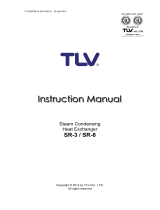
Product overview
The GTS humidifier LX series burns either natural or propane gas to heat and
boil fill water into steam for humidification. The unit has either one or two
burners that fire into a heat exchanger submerged in a tank of water. When
there is a call for humidity, the burners fire and generate steam until the call for
humidity ends.
UNIVERSAL WATER
DriSteem's GTS humidifier LX series incorporates universal water control for use
with any water type (well, tap, softened, DI or RO water). There is no need to
change control configurations based on water type when ordering equipment
or retrofitting to fit new water sources in the field. The water level control
algorithm monitors water quality and any changes over time to assure the user
of accurate control no matter the type of water that is used.
Gas connection
Gas valve
Electrical field connection
Primary heat exchanger
Blower
Steam outlet
Control components
Flue gas
vent
Duct dispersion option shown: Ultra-sorb Model LV
OM-7942
Supply water guidelines
Supply water quality is an important component
of humidifier reliability and maintenance.
Examples:
• Corrosive water can decrease the service life
of the humidifier.
• Excessive water hardness can increase the
humidifier maintenance requirements.
To maximize humidifier service life and
minimize humidifier maintenance, DriSteem has
established guidelines for supply water. See
Table 8-1.
Table 8-1:
DriSteem supply water guidelines
Chlorides*
Tap water
RO/DI water
Softened water
* Damage caused by
chloride corrosion is
not covered by your
DriSteem warranty.
< 50 ppm
< 5 ppm
< 25 ppm
Total hardness
Tap water < 500 ppm
(29 gpg)
pH
Tap water
RO/DI, softened water
6.5 to 8.5
7.0 to 8.0
Silica < 15 ppm
Supply water outside of the guidelines
may void your DriSteem warranty.
Please contact your DriSteem
Representative or DriSteem Technical
Support if you need advice.
FIGURE 8-1: GTS HUMIDIFIER LX SERIES
PRODUCT OVERVIEW
Supply water guidelines
Drain
Secondary
heat
exchanger
Combustion air
intake
Air gap
Open drain
Supply
water
connection
Flue gas condensate

9
GTS HUMIDIFIER LX SERIES INSTALLATION, OPERATION, AND MAINTENANCE MANUAL
Product overview
WATER LEVEL CONTROL
The LX series of GTS humidifiers control water level using a three-rod probe
(see Figure 9-1). All water types and conductivities work with the universal
water system. The user does not need to select a new water type or change
hardware to change water types. Additional valves and Vapor-logic algorithms
measure and control the water level for optimum efficiency and low water
safety conditions. Vapor-logic automatically provides a steady output while
maintaining the water level between the bottom and middle probes.
Supply water
connection
Control
components
Primary heat
exchanger
Air gap
Open drain
Water level sensing probe
Secondary heat
exchanger
Overflow
outlet
OM-7943
Gas valve
Blower
Note: Dashed lines indicate supplied by installer
Water level
is controlled
electronically using
three probes
Full
Overflow/foam detection
FIGURE 9-2: GTS HUMIDIFIER LX SERIES (MODELS LX-50 THROUGH LX-150)
FIGURE 9-1: WATER LEVEL CONTROL
Flue gas vent
VLC-OM-030
Gas connection
Drain
Electrical field
connection
Flue gas condensate
Steam outlet
Combustion air pipe
Low

10
GTS HUMIDIFIER LX SERIES INSTALLATION, OPERATION, AND MAINTENANCE MANUAL
Product overview
Supply water
connection
Control
components
Primary heat
exchanger
Air gap
Open drain
Water level sensing probe
Secondary heat
exchanger
Overflow
outlet
OM-7996
Gas valve
Blower
Note: Dashed lines indicate supplied by installer
FIGURE 10-1: GTS HUMIDIFIER LX SERIES (MODELS LX-400 THROUGH LX-600)
Flue gas vent
Gas connection
Drain
Electrical field
connection
Flue gas condensate
Steam outlet
Combustion air pipe

11
GTS HUMIDIFIER LX SERIES INSTALLATION, OPERATION, AND MAINTENANCE MANUAL
Models, capacities, electrical specifications, and weights
LP GAS
All models operate at rated input
HIGH ALTITUDE
The input shown6 in Table 11-2 is derate when operating units at a high
altitude. See the "Start-up procedure" on page 57 for adjusting oxygen
levels on the LX series gas valve.
Table 11-1:
GTS models, capacities, electrical specifications, turndown, and weights
GTS
model
Maximum
steam
capacity
Input
Water usage
at maximum
capacity
Tank
volume
GTS humidifier
LX series*
Turndown
Full load
amps*
Operating
weight
Shipping
(empty)
weight**
lbs/hr kg/h MBh kW m
3
/h
gals/
hr
litres/
hr
gals litres lbs kg lbs kg ratio lbs/hr
120V
60 Hz
230V
50 Hz
LX-50 50 23 61 17.8 1.7 6 23 14 53 304 138 187 85 5:1 10 2.0 1.5
LX-75 75 34 91.5 26.8 2.5 9 34 14 53 304 138 187 85 6:1 12.5 2.0 1.5
LX-100 100 45 122 35.8 3.4 12 45 13 49 300 136 192 87 8:1 12.5 2.0 1.5
LX-150 150 68 183 53.6 5.1 18 68 25 95 450 204 242 110 6:1 25 2.5 2.0
LX-200 200 91 244 71.5 6.8 24 91 42 159 706 320 356 161 6.7:1 30 4.0 2.5
LX-250 250 113 305 89.4 8.5 30 114 42 159 706 320 356 161 8.3:1 30 4.0 2.5
LX-300 300 136 360 105.5 10 36 136 41 155 709 321 367 166 10:1 30 4.0 2.5
LX-400 400 181 488 143 13.5 48 182 80 303 1259 571 593 269 13.3:1 30 6.5 3.5
LX-500 500 227 610 178.8 16.9 60 227 80 303 1259 571 593 269 16.7:1 30 6.5 3.5
LX-600 600 272 720 211 20 72 273 78 295 1265 574 615 279 20:1 30 6.5 3.5
* For outdoor enclosures, see Table 26-1.
** Add approximately 60-90 lbs (27-41 kg) for packaging material.
Table 11-2:
High altitude derate
Altitude
Input
derate %
feet meters
0–2000 0–610 0
2001–2500 610–765 2
2501–3000 765–915 4
3001–3500 915–1065 6
3501–4000 1065–1220 8
4001–4500 1220–1370 10
4501–5000 1370–1525 12
5001–5500 1525–1675 14
5501–6000 1675–1830 16
6001–6500 1830–1980 18
6501–7000 1980–2135 20
7001–7500 2135–2285 22
7501–8000 2285–2440 24
Important: See Pages 80 and 81 for
additional European model specifications and
capacity notes.
SPECIFICATIONS

12
GTS HUMIDIFIER LX SERIES INSTALLATION, OPERATION, AND MAINTENANCE MANUAL
Indoor dimensions
K
E
F
D
G
C
L
A
B
Side view Front view Top view
OM-7946
H
M
O
J
SPECIFICATIONS
FIGURE 12-1: LX MODELS 50 - 150 INDOOR UNIT DIMENSIONS
P
Q
J
T
S
R
N
FIGURE 12-2: LX MODELS 200 - 300 INDOOR UNIT DIMENSIONS
See "Indoor unit dimensions" on page 13-1.
See "Indoor unit dimensions" on page 13-1.
K
E
F
G
C
L
B
Side view Front view Top view
OM-8014
M
D
P
Q
T
S
R
N
A
H
J
O

13
GTS HUMIDIFIER LX SERIES INSTALLATION, OPERATION, AND MAINTENANCE MANUAL
Indoor dimensions
SPECIFICATIONS
Table 13-1:
Indoor unit dimensions
Description
LX-50, LX-75, LX-100 LX-150 LX-200, LX-250, LX-300 LX-400, LX-500, LX-600
inches mm inches mm inches mm inches mm
A Overall length 23.25 590 32.25 819 56 1422 56 1422
B Overall width 23.25 590 23.25 590 22 559 34 864
C Overall height 42.75 1085 42.75 1085 47 1194 53 1346
D
Flue position
4.3 109 4.3 109 8.7 221 14.5 368
E 4.4 112 4.4 112 5.61 143 5.6 142
F Flue diameter 3 76 3 76 4 102 6 152
G
Steam outlet position
3.8 97 3.8 97 7.1 180 7 178
H 5.3 135 5.3 135 6.9 175 7.4 188
J Steam outlet diameter 2 51 2 51 3 76 4 102
K
Gas inlet position
9.2 234 9.2 234 16.6 4022 16.6 422
L 4.6 119 4.6 119 14.3 363 14.3 363
M
Drain position
3.5 89 3.5 89 11 279 11 279
N 4.5 114 4.5 114 8 203 8 203
O
Combustion air
8.92 227 8.92 227 6.5 165 14.5 368
P 2.7 69 2.7 69 14 363 14.5 368
Q Combustion air diameter 3 76 3 76 4 102 6 152
R Flue and combustion air height 5.5 140 5.5 140 5.6 142 7.1 180
S
Fill valve connection position
6.59 167 6.59 167 22.4 569 22.4 569
T 5.60 142 5.60 142 12.4 315 12.4 315
K
E
F
G
C
L
B
Side view Front view Top view
OM-7998
M
D
J
FIGURE 13-1: LX MODELS 400 - 600 INDOOR UNIT DIMENSIONS
P
Q
T
S
R
N
For outdoor dimensions see page 21.
A
H

14
GTS HUMIDIFIER LX SERIES INSTALLATION, OPERATION, AND MAINTENANCE MANUAL
Location and clearance recommendations
FINDING A LOCATION
• Provide a level, solid foundation for the humidifier.
• The GTS humidifier LX series vent and air piping can be installed through
the roof or through a sidewall. Use only vent/air piping methods described
in this IOM. Locate the humidifier as near as possible to an outside wall
or accessible roof space so that the flue pipe from the humidifier is short,
direct, and limited to wind exposure.
• Locate the unit so it and its electrical components are protected from water
during humidifier operation and service.
• Install the humidifier in a location away (and protected) from drafts. Follow
the instructions concerning combustion and ventilation air.
• Locate the humidifier in an area where leakage from the tank or its
connections will not result in damage to the adjacent structure or to lower
floors of the structure. When such locations cannot be avoided, install
a suitable drain pan (adequately drained) under the humidifier (field
supplied). The pan must not restrict combustion airflow.
• If located in an insulated space, keep the humidifier free and clear of
insulating materials. Insulating material can be combustible. Inspect the
humidifier area when the humidifier is installed or when insulation is
added.
• See the combustion air and flue gas venting section on page 42 for
pipe termination locations and instructions.
INSTALLATION
WARNING
Installation requirements
The humidifier must be installed by
a qualified technician and meet the
requirements of all governing codes.
Failure to follow these instructions could
cause severe bodily injury or death.

15
GTS HUMIDIFIER LX SERIES INSTALLATION, OPERATION, AND MAINTENANCE MANUAL
Location and clearance recommendations
INSTALLATION
18" (457 mm)
1" (25 mm)
30" (762 mm) for
LX-50 through LX-150
54" (1372 mm) for
LX-200 through LX-600
FIGURE 15-1: LX SERIES CLEARANCE RECOMMENDATIONS (INDOOR UNITS)
OM-7947
36" (914 mm)
1" (25 mm)
Indoor Unit
Outdoor Unit
FIGURE 15-2: LX SERIES CLEARANCE RECOMMENDATIONS (OUTDOOR UNITS)
36" (914 mm)
36" (914 mm)
36" (914 mm)
36" (914 mm)
36" (914 mm) for
LX-50 through LX-150
54" (1372 mm) for
LX-200 through LX-600
OM-8012

16
GTS HUMIDIFIER LX SERIES INSTALLATION, OPERATION, AND MAINTENANCE MANUAL
INSTALLATION
Optional floor stand mount (Models 50, 75,100, and 150 only)
FIGURE 16-1: LX SERIES FLOOR STAND MOUNT ASSEMBLY FLOOR STAND MOUNTING INSTRUCTIONS
1. Refer to Figure 17-1 for assembly of the floor stand.
2. Use the hardware provided by DriSteem to assemble.
3. Arrange appropriate lifting mechanism and personnel
to mount the GTS humidifier LX series on the floor
stand. See Warning below.
4. Use the lifting hole on the base of humidifier to
carefully lift it off the ground. See Warning below.
5. Slowly lower the humidifier on the floor stand.
6. Secure the base of the humidifier to the floor stand
using sheet metal screws.
OM-7972
OM-7971
Notes:
• Weight of floor stand:
Models LX-50 - LX-100: 24 lbs (11 kg),
Model LX-150: 30 lbs (14 kg)
• Allows for condensate piping/pump
• Bottom supply water connection is located underneath the side
water connection. See fill valve connection position on page 13.
WARNING
HEAVY OBJECT
To avoid muscle strain or back injury, use lifting aids and
proper lifting techniques when removing or replacing.
Model LX-150
Models LX-50 - LX-100

17
GTS HUMIDIFIER LX SERIES INSTALLATION, OPERATION, AND MAINTENANCE MANUAL
C
OM-7962
A
21.125" (537mm)
FIGURE 17-1: LX SERIES WITH FLOOR STAND MOUNT (MODELS 50, 75, AND 100)
See "Indoor unit dimensions" on page 13-1.
B
OM-7970
INSTALLATION
Optional floor stand mount (Models 50, 75,100, and 150 only)
C
OM-8021
A
21.125" (537mm)
FIGURE 17-2: LX SERIES WITH FLOOR STAND MOUNT (MODEL 150)
See "Indoor unit dimensions" on page 13-1.
B
OM-8022

18
GTS HUMIDIFIER LX SERIES INSTALLATION, OPERATION, AND MAINTENANCE MANUAL
INSTALLATION
Optional wall mount (Models 50, 75 and 100 only)
OM-7993
22.88" (581 mm)
FIGURE 18-1: LX SERIES WITH WALL MOUNT
See "Indoor unit dimensions" on page 13-1.
OM-7992
24.63" (626 mm)
23.13" (587 mm)
42.75"
(1086 mm)
20.13"
(511 mm)
/