Page is loading ...

STS
®
Steam-to-Steam Humidifier
Installation, Operation,
and Maintenance Manual
READ AND SAVE THESE INSTRUCTIONS

ii
STS INSTALLATION, OPERATION, AND MAINTENANCE MANUAL
WARNINGS AND CAUTIONS
Warnings and cautions
WARNING
Indicates a hazardous situation that could result in death or
serious injury if instructions are not followed.
CAUTION
Indicates a hazardous situation that could result in damage to or
destruction of property if instructions are not followed.
mc_051508_1145
WARNING
Attention installer
Read this manual before installing, and leave this manual with product owner. This product must be installed by qualifi ed
HVAC and electrical contractors and in compliance with local, state, federal, and governing codes. Improper installation
can cause property damage, severe personal injury, or death as a result of electric shock, burns, or fi re.
DriSteem
®
technical support: 800-328-4447
Read all warnings and instructions
Read this manual before performing service or maintenance procedures on any part of the system. Failure to follow all
warnings and instructions could produce the hazardous situations described, resulting in property damage, personal injury,
or death.
Failure to follow the instructions in this manual can cause moisture to accumulate, which can cause bacteria and mold
growth or dripping water into building spaces. Dripping water can cause property damage; bacteria and mold growth can
cause illness.
mc_011909_1215
Hot surfaces and hot water
This steam humidifi cation system has extremely hot surfaces. Water in tank, steam pipes, and dispersion assemblies can
be as hot as 212 °F (100 °C). Discharged steam is not visible. Contact with hot surfaces, discharged hot water, or air
into which steam has been discharged can cause severe personal injury. To avoid severe burns, follow the cool-down
procedure in this manual before performing service or maintenance procedures on any part of the system.
mc_011909_1130

iii
STS INSTALLATION, OPERATION, AND MAINTENANCE MANUAL
Warnings and cautions
WARNING
Disconnect electrical power
Disconnect electrical power before installing supply wiring or performing service or maintenance procedures on any
part of the humidifi cation system. Failure to disconnect electrical power could result in fi re, electrical shock, and other
hazardous conditions. These hazardous conditions could cause property damage, personal injury, or death.
Contact with energized circuits can cause property damage, severe personal injury, or death as a result of electrical shock
or fi re. Do not open control cabinet door or remove subpanel access panels until electrical power is disconnected.
Follow the shutdown procedure below before performing service or maintenance procedures on any part of the system.
Shutdown procedure
To prevent serious injury, follow this shutdown procedure before performing service or maintenance procedures on this
humidifi er, after the tank has cooled down and drained.
1. Follow the “Cool down humidifi er” instructions on Page 50 (tap/softened water STS) or Page 53
(STS with RO/DI water option) to put the humidifi er at a safe temperature for service.
2. Use the Vapor-logic
®
keypad/display to change control mode to Standby.
3. Place all power disconnects in OFF position and lock in OFF position.
4. Close the fi eld-installed manual water supply shut-off valve.
5. Close the manual shut-off valve on the inlet steam supply.
CAUTION
Hot discharge water
Discharge water can be as hot as 212 °F (100 °C) and can damage the drain plumbing.
Humidifi ers equipped with a water tempering device need fresh make-up water in order to function properly. Make sure the water
supply to the water tempering device remains open during draining.
If the humidifi er is not equipped with a water tempering device, allow the tank to cool before opening the drain valve.
Excessive supply water pressure
Supply water pressure greater than 80 psi (550 kPa) can cause the humidifi er to overfl ow.
mc_123010_1520

iv
STS INSTALLATION, OPERATION, AND MAINTENANCE MANUAL
Table of contents
Attention installer
Read this manual before installing.
Leave manual with product owner.
Where to find more information
Our web site:
The following documents are available on our
web site: www.dristeem.com
• Catalogs
– STS
– Ultra-sorb
®
• Installation, Operation, and Maintenance
manuals (IOM)
– Ultra-sorb Models LV and LH
– Ultra-sorb Model XV
– Vapor-logic controller (includes humidifi er
operation and troubleshooting)
• DriSteem Humidifi cation System Design
Guide (includes steam loss tables and
general humidifi cation information)
DriCalc
®
:
DriCalc, our software for humidifi cation system
sizing and selection, can be ordered at our
web site. Also in Dri-calc:
• Library of installation guides
• Dispersion and sensor placement in ducts
and air handlers
• Vertical airfl ows
Call us at 800-328-4447
Obtaining documents from our web site or
from DriCalc is the quickest way to view our
literature, or we will be happy to mail literature
to you.
WARNINGS AND CAUTIONS . . . . . . . . . . . . . . . . . . . . . . . . . . . . . . . . . . . . . . . . . . . . . . . . . . .
ii
OVERVIEW. . . . . . . . . . . . . . . . . . . . . . . . . . . . . . . . . . . . . . . . . . . . . . . . . . . . . . . . . . . . . . . . .2
Product overview . . . . . . . . . . . . . . . . . . . . . . . . . . . . . . . . . . . . . . . . 2
Tap/softened water . . . . . . . . . . . . . . . . . . . . . . . . . . . . . . . . . . . . 2
RO/DI water option . . . . . . . . . . . . . . . . . . . . . . . . . . . . . . . . . . . 2
Water type conversion . . . . . . . . . . . . . . . . . . . . . . . . . . . . . . . . . 2
Dimensions . . . . . . . . . . . . . . . . . . . . . . . . . . . . . . . . . . . . . . . . . . . . 4
Capacities, electrical specifications, and weights . . . . . . . . . . . . . . . . . . 6
INSTALLATION . . . . . . . . . . . . . . . . . . . . . . . . . . . . . . . . . . . . . . . . . . . . . . . . . . . . . . . . . . . . . .7
Selecting a location . . . . . . . . . . . . . . . . . . . . . . . . . . . . . . . . . . . . . . 7
Mounting methods . . . . . . . . . . . . . . . . . . . . . . . . . . . . . . . . . . . . . . . 8
Mounting the humidifier . . . . . . . . . . . . . . . . . . . . . . . . . . . . . . . . . . . 9
Support legs . . . . . . . . . . . . . . . . . . . . . . . . . . . . . . . . . . . . . . . . 9
Wall brackets . . . . . . . . . . . . . . . . . . . . . . . . . . . . . . . . . . . . . . . . 9
H-legs . . . . . . . . . . . . . . . . . . . . . . . . . . . . . . . . . . . . . . . . . . . . . 9
Trapeze hanger . . . . . . . . . . . . . . . . . . . . . . . . . . . . . . . . . . . . . . 9
Weather cover . . . . . . . . . . . . . . . . . . . . . . . . . . . . . . . . . . . . . . . . . 10
Outdoor Enclosure . . . . . . . . . . . . . . . . . . . . . . . . . . . . . . . . . . . . . . 12
Electrical specifications . . . . . . . . . . . . . . . . . . . . . . . . . . . . . . . . . 13
Mounting . . . . . . . . . . . . . . . . . . . . . . . . . . . . . . . . . . . . . . . . . . 15
STS Outdoor Enclosure sequence of operation . . . . . . . . . . . . . . . . 17
Alternate water seal and drain valve piping . . . . . . . . . . . . . . . . . . 18
Piping: . . . . . . . . . . . . . . . . . . . . . . . . . . . . . . . . . . . . . . . . . . . . . . . 18
Drain . . . . . . . . . . . . . . . . . . . . . . . . . . . . . . . . . . . . . . . . . . . . 18
Fill . . . . . . . . . . . . . . . . . . . . . . . . . . . . . . . . . . . . . . . . . . . . . . . 20
Tap/softened water, one heat exchanger . . . . . . . . . . . . . . . . . . . 22
Tap/softened water, two heat exchangers . . . . . . . . . . . . . . . . . . . 23
RO/DI water option, one heat exchanger . . . . . . . . . . . . . . . . . . . 24
RO/DI water option, two heat exchangers . . . . . . . . . . . . . . . . . . 25
Pressurized steam supply . . . . . . . . . . . . . . . . . . . . . . . . . . . . . . . 26
Humidification steam outlet . . . . . . . . . . . . . . . . . . . . . . . . . . . . . 27
Wiring . . . . . . . . . . . . . . . . . . . . . . . . . . . . . . . . . . . . . . . . . . . . . . 28
Wiring diagram locations . . . . . . . . . . . . . . . . . . . . . . . . . . . . . . 28
Electrical installation . . . . . . . . . . . . . . . . . . . . . . . . . . . . . . . . . . 28
Wiring requirements . . . . . . . . . . . . . . . . . . . . . . . . . . . . . . . . . . 28
Control wiring . . . . . . . . . . . . . . . . . . . . . . . . . . . . . . . . . . . . . . 29
Grounding requirements . . . . . . . . . . . . . . . . . . . . . . . . . . . . . . . . 29
Sensor placement . . . . . . . . . . . . . . . . . . . . . . . . . . . . . . . . . . . . . . . 30
Dispersion: . . . . . . . . . . . . . . . . . . . . . . . . . . . . . . . . . . . . . . . . . . . . 31
Selecting the dispersion assembly location . . . . . . . . . . . . . . . . . . 31
Interconnecting piping requirements . . . . . . . . . . . . . . . . . . . . . . . 32
Drip tee installation . . . . . . . . . . . . . . . . . . . . . . . . . . . . . . . . . . . 34
Single tube and multiple tube . . . . . . . . . . . . . . . . . . . . . . . . . . . . 35
Rapid-sorb . . . . . . . . . . . . . . . . . . . . . . . . . . . . . . . . . . . . . . . . . 40
Ultra-sorb . . . . . . . . . . . . . . . . . . . . . . . . . . . . . . . . . . . . . . . . . . 46

1
STS INSTALLATION, OPERATION, AND MAINTENANCE MANUAL
Table of contents
OPERATION . . . . . . . . . . . . . . . . . . . . . . . . . . . . . . . . . . . . . . . . . . . . . . . . . . . . . . . . . . . . . . 47
Start-up procedure . . . . . . . . . . . . . . . . . . . . . . . . . . . . . . . . . . . . . . 47
Start-up checklist . . . . . . . . . . . . . . . . . . . . . . . . . . . . . . . . . . . . . . . . 48
MAINTENANCE . . . . . . . . . . . . . . . . . . . . . . . . . . . . . . . . . . . . . . . . . . . . . . . . . . . . . . . . . . . 49
Water quality . . . . . . . . . . . . . . . . . . . . . . . . . . . . . . . . . . . . . . . . . 49
Tap/softened water . . . . . . . . . . . . . . . . . . . . . . . . . . . . . . . . . . . . . . 50
RO/DI water option . . . . . . . . . . . . . . . . . . . . . . . . . . . . . . . . . . . . . 53
Outdoor Enclosure . . . . . . . . . . . . . . . . . . . . . . . . . . . . . . . . . . . . . . 55
REPLACEMENT PARTS . . . . . . . . . . . . . . . . . . . . . . . . . . . . . . . . . . . . . . . . . . . . . . . . . . . . . . 56
Humidifier tank . . . . . . . . . . . . . . . . . . . . . . . . . . . . . . . . . . . . . . . . 56
Control cabinet . . . . . . . . . . . . . . . . . . . . . . . . . . . . . . . . . . . . . . . . 58
Outdoor Enclosure . . . . . . . . . . . . . . . . . . . . . . . . . . . . . . . . . . . . . . 59
WARRANTY . . . . . . . . . . . . . . . . . . . . . . . . . . . . . . . . . . . . . . . . . . . . . . . . . . . . . . . . . . . . . . 60

2
STS INSTALLATION, OPERATION, AND MAINTENANCE MANUAL
STS (steam-to-steam) humidifi ers use pressurized boiler steam to heat clean fi ll
water into chemical-free steam for humidifi cation. See Figure 3-1.
STS humidifi ers are designed for use with tap/softened water and are
available with an option for RO/DI water (water that has been treated using
reverse osmosis, or deionized water).
TAP/SOFTENED WATER
A conductivity probe (Figure 3-2) monitors the water level in the tap/softened
water STS humidifi er; therefore, water conductivity must be at least 30 μS/
cm for proper operation. A tap/softened water STS humidifi er will not operate
with RO/DI water. For RO/DI water, use STS with the RO/DI water option.
RO/DI WATER OPTION
STS humidifi ers with the RO/DI water option control water level with a fl oat
valve (Figure 3-3). Float valves are compatible with RO/DI water only.
Humidifi ers with the RO/DI water option are virtually maintenance free and
require little or no downtime.
WATER TYPE CONVERSION
STS tap/softened water humidifi ers can be converted in the fi eld for use with
RO/DI water, and STS RO/DI water humidifi ers can be converted in the fi eld
for use with tap/softened water. Contact your DriSteem representative or
distributor for parts and instructions.
Product overview
OVERVIEW
mc_071912_1545
Supply water guidelines
Supply water quality is an important component
of humidifi er reliability and maintenance.
Examples:
• Corrosive water can decrease the service
life of the humidifier.
• Excessive water hardness can increase the
humidifier maintenance requirements.
To maximize humidifi er service life and
minimize humidifi er maintenance, DriSteem
has established guidelines for supply water
See Table 2-1.
Table 2-1:
DriSteem supply water guidelines
Chlorides*
RO or DI water
Softened water
Tap water
* Damage caused by
chloride corrosion is
not covered by your
DriSteem warranty.
< 5 ppm
< 25 ppm
< 50 ppm
Total hardness
Tap water < 500 ppm
pH
RO, DI, or softened water
Tap water
7 to 8
6.5 to 8.5
Silica < 15 ppm
You may wish to take action to mitigate
potential negative effects to your
humidifi er. Supply water outside of these
guidelines may void your DriSteem
warranty. Please contact your DriSteem
Representative or DriSteem Technical
Support if you need advice.

3
STS INSTALLATION, OPERATION, AND MAINTENANCE MANUAL
Tap/softened water STS humidifi er
Air gap
Water seal
Condensate return
Steam trap
Automatic steam valve
Open drain
Manual drain valve
Heat exchanger
Float valve water level control
OM-939
Notes:
• Drain piping material must be suitable for 212 °F (100 °C) water.
• See the piping drawings on Pages 22 through 25.
Humidifi cation steam outlet
Automatic steam valve
Boiler steam
Steam trap
Condensate return
Water seal
Air gap
Open drain
Manual drain or optional
motorized drain valve
Heat exchanger
OM-938
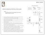
STS humidifi er with the RO/DI water option
OVERVIEW
Fill valve
Float rod
Float ball
VLC-OM-026
Humidifi ers using RO/DI water control water
level using a fl oat valve. An optional low-water
cutoff switch is available as a remote water
indicator.
mc_030910_1336-STS
Humidifi cation steam outlet
Probe water level control
Boiler steam
Product overview
Humidifi ers using tap or softened water control
water levels electronically using a three-rod
probe. The controller responds with the above
actions when the water level reaches each rod.
VLC-OM-030
Fill valve opens when
water level is below this
probe.
Low-water cutoff.
Pressurized steam to
heat exchanger is cut if
water level drops below
this probe (if steam to
STS heat exchanger
is controlled by
Vapor-logic).
Fill valve closes when
water level rises to this
probe.
mc_030910_1335-STS
FIGURE 3-1: STS HUMIDIFIERS FIGURE 3-2: WATER LEVEL CONTROL
FOR TAP/SOFTENED WATER HUMIDIFIER
FIGURE 3-3: WATER LEVEL CONTROL
FOR RO/DI-WATER OPTION HUMIDIFIER

4
STS INSTALLATION, OPERATION, AND MAINTENANCE MANUAL
OVERVIEW
Dimensions
Front view
OM-936
Side view
Front view Side view
mc_010511_1012-tap
mc_010511_1013-tap
Mounting holes:
Models 25–100: 5/16" (8 mm) slot
Models 200 & 400: 1/2" (12 mm) slot
B
A
E
H
D
C
OM-932
OM-931
J
K
L
M
B
E
F
C
H
G
J
A
D
L
K
M
Mounting hole:
1/2" dia.
(12 mm) slot
Notes:
• Tap/softened water model shown
• See dimensions in Tables 5-1 and 5-2
Notes:
• Tap/softened water model shown
• See dimensions in Tables 5-1 and 5-2
FIGURE 4-1: DIMENSIONS, STS MODELS 25, 50, 100, 200, AND 400 (WITH COPPER OR STAINLESS STEEL HEAT EXCHANGERS)
FIGURE 4-2: DIMENSIONS, STS MODEL 800 (WITH COPPER OR STAINLESS STEEL HEAT EXCHANGERS)

5
STS INSTALLATION, OPERATION, AND MAINTENANCE MANUAL
OVERVIEW
Dimensions
Table 5-2:
Dimensions, STS with stainless steel heat exchangers
Description
See drawings in Figures 4-1 and
4-2
STS model*
25S 50S 100S 200S 400SNC 800SNC
inches mm inches mm inches mm inches mm inches mm inches mm
A Height** 19.50 495 19.50 495 19.50 495 19.50 495 19.50 495 29.75 756
B Width 14.75 375 14.75 375 19.25 489 30.25 768 30.25 768 30.25 768
C Length 23.65 600 39.65 1007 39.65 1007 55.15 1401 55.15 1401 55.15 1401
D
Bottom to supply inlet of fi rst heat
exchanger
6.85 174 6.85 174 6.85 174 6.85 174 6.85 174 6.85 174
E
Bottom to return outlet of fi rst heat
exchanger
3.35 85 3.35 85 3.35 85 3.35 85 3.35 85 3.35 85
F
Bottom to supply inlet of second
heat exchanger
——————————14.5 368
G
Bottom to return outlet of second
heat exchanger
——————————11.0 279
H Side to heat exchanger 3.25 83 3.25 83 3.25 83 3.25 83 3.25 83 3.25 83
J Pressurized steam supply inlet
3/4" pipe
thread
DN20
1" pipe
thread
DN25
1" pipe
thread
DN25
1½" pipe
thread
DN40
1½" pipe
thread
DN40
1½" pipe
thread
DN40
K Pressurized condensate return outlet
3/4" pipe
thread
DN20
3/4" pipe
thread
DN20
3/4" pipe
thread
DN20
3/4" pipe
thread
DN20
3/4" pipe
thread
DN20
3/4" pipe
thread
DN20
L Side to steam outlet 6.25 159 8.63 219 9.63 245 13.00 330 13.00 330 13.00 330
M Front to steam outlet 2.50 64 2.25 57 2.75 70 3.75 95 3.75 95 3.75 95
* C, S, and SNC in model numbers are explained in Table 6-1.
** Add 23.5" (597 mm) to overall height when STS is mounted on four support legs. Add 22.5" (572 mm) to overall height when STS is mounted
on two H-legs.
Table 5-1:
Dimensions, STS with copper heat exchangers
Description
See drawings in Figures 4-1 and 4-2
STS model*
25C 50C 100C 400C 800C
inches mm inches mm inches mm inches mm inches mm
A Height** 19.50 495 19.50 495 19.50 495 19.50 495 29.75 756
B Width 14.75 375 14.75 375 19.25 489 30.25 768 30.25 768
C Length 23.65 600 39.65 1007 39.65 1007 55.15 1401 55.15 1401
D Bottom to supply inlet of fi rst heat exchanger 6.63 168 6.63 168 6.63 168 6.63 168 6.63 168
E Bottom to return outlet of fi rst heat exchanger 3.63 92 3.63 92 3.63 92 3.63 92 3.63 92
F Bottom to supply inlet of second heat exchanger ————————14.28 363
G Bottom to return outlet of second heat exchanger ————————11.24 285
H Side to heat exchanger 3.25 83 3.25 83 3.25 83 3.25 83 3.25 83
J Pressurized steam supply inlet
3/4" pipe
thread
DN20
1¼" pipe
thread
DN32
1¼" pipe
thread
DN32
1½" pipe
thread
DN40
1½" pipe
thread
DN40
K Pressurized condensate return outlet
3/4" pipe
thread
DN20
3/4" pipe
thread
DN20
1¼" pipe
thread
DN32
1¼" pipe
thread
DN32
1¼" pipe
thread
DN32
L Side to steam outlet 6.25 159 8.63 219 9.63 245 13.00 330 13.00 330
M Front to steam outlet 2.50 64 2.25 57 2.75 70 3.75 95 3.75 95
* C, S, and SNC in model numbers are explained in Table 6-1.
** Add 23.5" (597 mm) to overall height when STS is mounted on four support legs. Add 22.5" (572 mm) to overall height when STS is mounted
on two H-legs.

6
STS INSTALLATION, OPERATION, AND MAINTENANCE MANUAL
Capacities, electrical specifi cations, and weights
OVERVIEW
Table 6-3:
STS humidifier weights
STS model
Shipping weight Operating weight*
lbs kg lbs kg
25 95 43 175 79
50 125 57 336 152
100 139 63 350 159
200 245 111 850 386
400 320 145 950 431
800 410 186 1450 658
* Operating weight does not include weight of interconnecting piping provided by installer.
Table 6-1:
STS humidifier models and capacities with copper heat exchangers
STS models
Steam pressure at connection to STS steam valve (valve provided by DriSteem)
5 psi (34 kPa) 10 psi (69 kPa) 13 psi (90 kPa) 15 psi (103 kPa)
lbs/hr kg/h lbs/hr kg/h lbs/hr kg/h lbs/hr kg/h
25C 20 9 70 32 100 45 120 54
50C 50 23 150 68 200 91 240 109
100C 100 45 300 136 400 181 480 218
400C 300 136 580 263 720 327 790 358
800C 650 295 1275 578 1500 680 1600 726
mc_010411_1645
Table 6-2:
STS humidifier models and capacities with stainless steel heat exchangers
STS models
Steam pressure at connection to STS steam valve (valve provided by DriSteem)
5 psi (34 kPa) 10 psi (69 kPa) 13 psi (90 kPa) 15 psi (103 kPa)
lbs/hr kg/h lbs/hr kg/h lbs/hr kg/h lbs/hr kg/h
25S 10 5 251130143516
50S 30 14 55 25 75 34 80 36
100S 60 27 110 50 140 64 150 68
200S 150 68 290 132 360 163 390 177
400SNC 170 77 392 178 552 250 637 289
800SNC 212 96 825 374 1095 497 1223 555
mc_010411_1645
For use with tap/softened or RO/DI water:
• STS models ending in C (copper heat
exchangers with a nickel coating)
• STS models ending in S (stainless steel heat
exchangers with a Tefl on coating)
For use with RO/DI water option only:
STS models ending in SNC (stainless steel heat
exchangers with no coating)
Table 6-4:
STS humidifier electrical specifications
North America 120 V single phase max 3 amps
Europe 230 V single phase max 3 amps

7
STS INSTALLATION, OPERATION, AND MAINTENANCE MANUAL
INSTALLATION
When selecting the location of the humidifi er, consider the following:
• Maximum ambient temperature for control cabinet is 104 °F (40 °C).
• Noises inherent to operation such as STS water fi ll cycles
• Easy access for maintenance
• Critical service and maintenance clearances around humidifi er — primarily
top, left side, and front (see Figure 7-1).
• Convenient location to dispersion system for routing of steam hose or tubing
• Electrical connections — power, control, and safety circuits
• Steam supply piping connections — inlet steam piping, condensate piping,
and optional equipment (see Figure 26-1)
• Plumbing connections — supply water, drain piping, and condensate return
piping
• Water seal requirements
• Avoid locations above critical equipment or processes to avoid damage to
the equipment below in the event of a water leak.
• Avoid locations close to sources of electromagnetic emissions such as
power distribution transformers and high horsepower motors controlled by
variable frequency drives.
Selecting a location
DC-1452
Top: 18" (457 mm)*
Rear: 6" (152 mm)
Right
side:
6" (152 mm)
Bottom:
24" (610 mm)
Front: 36" (914 mm)
* Minimum access clearance of 18" (457 mm) recommended for periodic removal of top cover
for access to tank.
mc_010511_1742-tap
Left side:
36" (914 mm) with mounted control cabinet.
6"(152) without mounted control cabinet
Tap/softened water
model shown
FIGURE 7-1: RECOMMENDED CLEARANCES

8
STS INSTALLATION, OPERATION, AND MAINTENANCE MANUAL
INSTALLATION
OM-933
Optional set of four legs and hardware
OM-947
DriSteem optional wall
brackets (two required)
B
A
DC-1454
STS model
AB
in. mm in. mm
25 and 50 15.5 394 24 610
100 21 533 30 762
Due to size and weight, STS models
200, 400, and 800 must be mounted
on H-legs.
mc_010511_1740-tap
mc_010511_1741-tap
mc_010511_1743-tap
mc_010511_1744-tap
Tap/softened water model shown
Tap/softened water model shown
Tap/softened water model shown
Mounting methods
Notes:
1. Secure rods to overhead construction.
2. 3/8" (M10) threaded rod of length required.
3. Angle or channel sized to properly support
humidifi er.
4. Humidifi er drain to appropriate building
waste. Do not drain humidifi er directly into
drip pan. Install water seal as shown on
Pages 22 through 25.
5. Drip pan (by installer) recommended in
overhead installations to prevent possible
water damage to equipment below.
Provide 18"
(457 mm)
minimum
clearance
above cover
DC-1453
See Note 1
See Note 2
See Note 3
See Note 4
25%
larger than
humidifi er
1¼" (DN32)
minimum
See Note 5
Tap/softened water model shown
FIGURE 8-1: SUPPORT LEGS, STS MODELS 25, 50, AND 100 ONLY FIGURE 8-2: TRAPEZE HANGER, STS
MODELS 25, 50, AND 100 ONLY
FIGURE 8-3: WALL BRACKETS, STS MODELS 25, 50, AND 100 ONLY
FIGURE 8-4: H-LEGS, STS MODELS 200, 400, AND 800 ONLY

9
STS INSTALLATION, OPERATION, AND MAINTENANCE MANUAL
INSTALLATION
Table 9-1:
STS mounting options
Mounting
method
STS model
25, 50, 100 200, 400, 800
Trapeze hanger standard —
H-legs — standard
Support legs optional —
Wall brackets optional —
Mounting the humidifi er
Important:
Installation must comply with local governing
codes.
These mounting methods are the only options
available to maintain compliance to the UL
998 standard. Alternate mounting methods will
compromise the humidifi er’s CE, ETL, and C-ETL
approval.
Support legs, trapeze hanger, and wall
brackets are not available for STS models 200,
400, and 800.
The STS humidifi er tank must be level from side to side and front to back. For
all mounting methods, shim and adjust when mounting, and verify that tank is
level after it is fi lled and at operating weight.
SUPPORT LEGS
See Figure 8-1. Use the enclosed bolts, nuts, and washers to fasten the
legs to the tank.
WALL BRACKETS
See Figure 8-3. DriSteem does not recommend mounting STS model 200,
400, or 800 with wall brackets. DriSteem recommends using 3/8" (M10)
fasteners.
• Concrete or block wall: Use concrete anchors (expansion bolts) rated for the
operating weight of the STS humidifi er. Position the wall brackets so they
are fl ush with the front and back fl anges of the tank.
• Wood stud wall: Mount two horizontal 2 × 4 boards
(100 mm × 50 mm timbers) 16" (404 mm) on center:
– STS 25: Lag bolt (coach screw) the 2 × 4s to two studs.
– STS 50: Lag bolt the 2 x 4s to three studs.
– STS 100: Lag bolt the 2 x 4s to four studs.
Lag bolt the wall brackets to the horizontal 2 × 4s. Position the wall brackets
fl ush with front and back fl anges of tank.
• Metal stud wall: Follow the wood stud wall guidelines above, but provide
a second set of 2 × 4s (100 mm × 50 mm timbers) on the backside of the
wall. Run bolts with washers through the face 2 × 4, through each metal
stud, and through the backside 2 × 4. Fasten the bolts and the face and
backside 2 x 4s to the wall with washers and nuts.
H-LEGS
See Figure 8-4. With the STS tank securely held in place above the fl oor,
attach front and rear supports using the supplied 3/8" (M10) bolts, nuts, and
washers. Make sure the bottom of the tank is supported by the H -leg supports;
this can be accomplished by having the bolts slightly loose as the unit is
lowered to the fl oor, then tighten them after the unit is place.
TRAPEZE HANGER
See Figure 8-2. Secure the threaded rods to an overhead structure strong
enough to support the operating weight of the humidifi er, fi eld-installed piping,
and (if mounted on the humidifi er) control cabinet.
For overhead installations, install a drip pan to prevent possible damage to
equipment below in the event of a water leak.

10
STS INSTALLATION, OPERATION, AND MAINTENANCE MANUAL
Weather cover
INSTALLATION
OM-7466
Table 10-2:
Weather cover dimensions
Letter Description
STS 25 to 100 STS 200 to 800
inches mm inches mm
A Height 62 1575 66 1676
B Length 43.5 1105 53 1346
C Width 62 1575 78.25 1988
D Distance from bottom 22 559 22 559
mc_012511_1605
OM-7465
Table 10-1:
Weather cover weights
Weather cover size lbs kg
STS 25 to 100 425 193
STS 200 to 800 550 250
mc_012511_1600
mc_012511_1606
mc_012511_1607
D
B
C
A
Panel
Hinged door
Panel
Panel
Panel
Hinged door
FIGURE 10-1: WEATHER COVER EXPLODED VIEW
FIGURE 10-2: WEATHER COVER DIMENSIONS

11
STS INSTALLATION, OPERATION, AND MAINTENANCE MANUAL
INSTALLATION
Weather cover
The optional STS weather cover is water-resistant and designed to protect an
STS humidifi er from rain and sun. This weather cover has been tested and
approved by ETL Testing Laboratories, Inc., and is listed to UL Standard 1995
and certifi ed to CAN/CSA Standard C22.2 No. 236.
The weather cover is fully assembled at the DriSteem factory.
INSTALLATION NOTES
Open the hinged doors to make necessary connections to the humidifi er. Refer
to the installation section of this manual for all elec tri cal, supply water, and
drain con nec tion requirements.
INSTALLATION ISSUES SPECIFIC TO WEATHER COVER APPLICATIONS
• Installation must comply with all governing codes.
• The bottom of the weather cover is open to ac com mo date piping and
electrical con nec tions.
• Electrical connections must be made with approved, outdoor-rated,
watertight conduit.
• Freeze protection must be provided on all water piping.
• Steam supply must be insulated.
• Avoid using steam hose in outdoor applications — the effects of ultraviolet
rays will prematurely age the steam hose.
• Installer must drill a hole in weather cover for steam piping. Seal after
making steam connection to maintain weather protection.
• The steam outlet must be isolated with a union to allow easy disconnection
of the steam supply. This allows easy removal of the weather cover to
access the STS for service and maintenance.
ANNUAL WEATHER COVER MAINTENANCE REQUIREMENTS
• Check all fasteners and verify they are secure.
• Check for any sign of leakage — trace back to origin and repair.

12
STS INSTALLATION, OPERATION, AND MAINTENANCE MANUAL
Outdoor Enclosure
INSTALLATION
Notes:
1. The Outdoor Enclosure has two available steam dis tri bu tion confi gurations. The standard con fi g u ra tion has a steam outlet on the right side of the
Outdoor Enclosure for con nect ing to steam dispersion unit piping. The optional internal steam dis tri bu tion con fi g u ra tion routes steam within the
Outdoor Enclosure and down through the enclosure pipe chase into a building.
2. There are four knockouts located on the right and left side of the enclosure. Knockout sizes are 1½" (hole dia. 50 mm) for STS models 25-100, and
2" (hole dia. 63.5 mm) for STS models 200-800. Run the electrical power into the en clo sure at these knockouts.
3. All piping from the STS unit to the steam outlet is stainless steel pipe. Depending on the application, tubing or DriSteem steam hose is recommended
for interconnecting piping from steam outlet to dispersion assembly.
4. Install a riser trap in the branch line leading to the humidifi er.
5. The preferred location for the STS steam control valve is inside the Outdoor Enclosure. If one of these valves must be located inside the building, it
must be located within 6' (1.8 m) of the humidifi er to reduce pressure drop.
6. See the dimensions in Table 13-1.
Table 12-2:
Outdoor Enclosure weights
STS model
Shipping weight* Operating weight*
lbs kg lbs kg
25 600 272 680 308
50 625 284 840 381
100 640 290 860 390
200 1050 476 1650 748
400 1125 510 1750 794
800 1225 556 2250 1021
* Includes humidifi er
mc_012611_1016
Table 12-1:
Outdoor Enclosure connection sizes
Description
STS model
25 – 100 200 – 800
Water makeup
(fi ll)
1/4” pipe thread (DN8) 1/4” pipe thread (DN8)
Drain 3/4” (DN20) 1” (DN25)
Condensate
return
3/4” pipe thread (DN20) 3/4” pipe thread (DN20)
Steam outlet See Table 27-1.
mc_012611_1017
mc_012511_1635
DC-1476
Ventilation fans
Power block
Knockouts, 4" (102 mm) on center
Enclosure drain 1½" pipe thread
(DN40) with male nipple
Pipe chase
G
A
Standard steam outlet
Optional steam outlet
See Note 2
STS humidifi er
L
K
6.5"
FIGURE 12-1: OUTDOOR ENCLOSURE WITH STANDARD OR OPTIONAL STEAM OUTLET, ELEVATION VIEW

13
STS INSTALLATION, OPERATION, AND MAINTENANCE MANUAL
INSTALLATION
Table 13-1:
Outdoor Enclosure dimensions*
Item Description
STS model
25–100 200–800
inches mm inches mm
A Enclosure height 56.00 1422 66.00 1676
B Enclosure width 36.00 914 46.00 1168
C
Pipe chase position
4.50 114 4.50 114
D 2.00 57 3.50 89
E
Pipe chase size
20.00 508 32.00 312
F 8.00 203 10.00 254
G
Steam pipe position
6.00 152 8.50 216
H 18.63 473 22.00 559
J 14.50 368 20.50 521
K 12.25 311 11.00 279
L Enclosure length 60.00 1524 78.00 1981
* See drawings in Figures 12-1 and 13-1.
mc_012611_1015
Outdoor Enclosure
DC-1478
B
Standard steam outlet (exits enclosure here)
Intake ven ti la tion fan
D
C
Pipe chase extending 1" (25 mm) above enclosure fl oor
STS hu mid i fi er
Elec tri cal and cleanout access door
Control panel heater
Control panel
Enclosure drain
F
E
Optional steam outlet
(exits enclosure through pipe chase)
Valve access door:
• Models 25-100 have one access door
• Models 200-800 have two access doors
Intake ventilation fan
Valve section heater
Valve access door
J
H
mc_012611_0837
Table 13-2:
STS Outdoor Enclosure electrical
specifications
Voltage Current
Maximum
disconnect
Outdoor
Enclosure
without
heater
package
120 Vac,
50/60 Hz
3.5 A 10 A
Outdoor
Enclosure
with heater
package
120 Vac,
50/60 Hz
13.5 A 20 A
FIGURE 13-1: OUTDOOR ENCLOSURE, TOP VIEW
ELECTRICAL SPECIFICATIONS

14
STS INSTALLATION, OPERATION, AND MAINTENANCE MANUAL
Outdoor Enclosure
INSTALLATION
Open to drain
Vacuum breaker (by installer)
Disconnect (by installer); see Detail A
120V supply.
Refer to Table 13-2 for electrical requirements.
Open drain
(See Note 4)
Heated building interior
Normally open (fail open) min
1/2" electric valve (by installer)
Optional water seal (P-trap)
drain line, min. 1½" (DN40)
(See Note 3)
Roof decking
Detail A
120 V
N
To valves
(by installer)
(See Note 1)
To STS
humidifi er
OM-7558
Drain line, min. 1½" electric
valve (See Note 3)
Domestic water, 80 psig
(582 kPa) maximum
Normally closed
(fail closed) min
3/8" electric
valve (by installer)
Normally closed fi ll
valve (by factory)
Disconnect
box
120 V from unit
disconnect or other
source (See Note 1)
Make-up water supply
piping (by installer)
(See Note 2)
Open drain
(See Note 4)
Humidifi er
Notes:
1. Insulate supply water piping to avoid dripping from condensation. To ensure that water does not remain in the fi ll line and freeze if there is a loss
of power, DriSteem recommends fi eld installing additional valves upstream of the fi ll valve in a conditioned space. Power these valves on the same
circuit that supplies the STS (as shown above); if the power goes off, water drains out of the fi ll line to prevent freezing.
2. Ensure that water lines are protected from freezing conditions.
• Install heat tracing and insulation on fi ll piping inside the Outdoor Enclosure.
• In extreme or critical applications in which the unlikely event of a water leak could cause severe damage, DriSteem recommends a thermostat
with a remote sensor on the fi ll line to cut power to the STS and safety valves to stop fi ll water to the STS and drain the fi ll piping when the
temperature is below freezing.
3. DriSteem recommends copper or iron drain piping for Outdoor Enclosures. On a loss of power the tank water will drain, but not be cooled by
the Drane-kooler because of the fi eld supplied safety shut-off valves. If it is critical to keep the Drane-kooler functional in the case of a power loss,
disconnect the Drane-kooler and relocate it down inside the conditioned space of the building. Pipe the supply water for the Drane-kooler before the
safety shut-off valves.
4. If copper or iron piping is used for both the fi ll and drain piping, these drains may be tied together. Locate 1" air gap only in spaces with adequate
temperature and air movement to absorb fl ash steam; otherwise, condensation may form on nearby surfaces. Refer to governing codes for drain
pipe size and maximum discharge water temperature.
mc_011311_1705
FIGURE 14-1: OUTDOOR ENCLOSURE INSTALLATION DETAIL

15
STS INSTALLATION, OPERATION, AND MAINTENANCE MANUAL
DC-1478
B
Standard steam outlet (exits enclosure here)
Intake ven ti la tion fan
D
C
Pipe chase extending 1" (25 mm) above enclosure fl oor
STS hu mid i fi er
Elec tri cal and cleanout access
door
Control panel heater
Control panel
Enclosure drain
E
Optional steam outlet
(exits enclosure through pipe chase)
Valve access door:
• Models 25-100 have one access door
• Models 200-800 have two access doors
Intake ventilation fan
Valve section heater
Valve access door
J
H
Outdoor Enclosure
INSTALLATION
F
MOUNTING
• Outdoor Enclosure must be level and positioned with enough clearance to
open access doors.
• Verify that position of pad or curb properly supports Outdoor Enclosure,
and that support structure dimensions coincide with unit dimensions.
• Locate unit so air intakes are not close to exhaust fan outlets, gasoline
storage, or other contaminants that could potentially cause dangerous
situations. Using or storing gasoline or other fl ammable vapors and liquids
in open containers in vicinity of Outdoor Enclosure is hazardous.
• When located on roof, Outdoor Enclosure air intakes must be a minimum
of 14" (356 mm) above roof to prevent intake of snow or splashed rain.
Position Outdoor Enclosure so prevailing winds do not blow into air intakes.
• Remove all shipping brackets and other packaging prior to installing the
unit.
• During transit, unloading, and setting of the unit, bolts and nuts may have
become loosened. Check that all nuts are tightened.
Important note about STS Outdoor
Enclosure installation
• Install a riser trap in the branch line leading
to the humidifi er.
• The preferred location for the STS steam
control valve is inside the Outdoor Enclosure.
If one of these valves must be located inside
the building, it must be located within 6'
(1.8 m) of the humidifi er to reduce pressure
drop.
FIGURE 15-1: STS OUTDOOR ENCLOSURE, TOP VIEW

16
STS INSTALLATION, OPERATION, AND MAINTENANCE MANUAL
Outdoor Enclosure
DC-1110
Flush
14"
(356 mm)
OM-1095
Curb
INSTALLATION
MOUNTING (CONTINUED)
• There are four knockouts on the right and left side of the enclosure. It is
recommended that electrical power is run into enclosure at these knockouts.
• Outdoor Enclosure is designed for lifting by two methods:
– Preferred method of lifting is by forklift. This is only possible if the forks
extend across entire unit. Forks that do not extend across entire unit
could cause tipping, resulting in unsafe conditions or damage to the
unit.
– Alternative method of lifting is through unit’s channel base frame and/
or special lifting lug hooks installed on the unit. Use a load spreader of
suffi cient width to ensure that lifting cables clear sides of unit. If such a
spreader is not available, insert wood strips between cables and unit
where necessary. All four lifting points must be used; they are marked
“lift here” on the unit.
In both cases it must be lifted from the bottom base and kept level, and
it must not tip, fall, or twist. If unit is severely twisted during handling,
permanent damage could occur. It is installer’s responsibility to verify
handling equipment’s capability to safely handle Outdoor Enclosure.
• Outdoor Enclosure has two available steam distribution confi gurations:
– Standard confi guration is a steam outlet on one side of enclosure for
connecting to steam dispersion unit piping.
– Optional internal confi guration routes steam within Outdoor Enclosure
and down through pipe chase into building.
See the drawings beginning on Page 12.
• Pipe chase is inside enclosure. Cover for pipe chase is provided to maintain
proper pressure in enclosure if this opening is not utilized. However, it is
recommended that this pipe chase be used for both supply water piping
and drain piping, in which case pipe chase cover should be removed.
Install insulation rated for 212 °F (100 °C) to completely fi ll area around
pipes to maintain proper enclosure pressure.
• When enclosure is pad mounted or when pipe chase cannot be used,
supply water and drain piping can be run through the knockouts —
preferably on side opposite utility connections.
• When ordered with heater package, two thermostat-controlled strip heaters
are provided to keep enclosure at constant minimum temperature: one
heater is in control cabinet section, and one heater is in front section.
• Enclosure drain is provided. In case of water leak, water will drain from
enclosure through this drain.
FIGURE 16-1: OUTDOOR ENCLOSURE
MOUNTING OPTIONS
/